EP0973054A2 - Komplexer optischer Schalter und diesen Schalter verwendendes optisches Kommunikationsgerät - Google Patents
Komplexer optischer Schalter und diesen Schalter verwendendes optisches Kommunikationsgerät Download PDFInfo
- Publication number
- EP0973054A2 EP0973054A2 EP99304871A EP99304871A EP0973054A2 EP 0973054 A2 EP0973054 A2 EP 0973054A2 EP 99304871 A EP99304871 A EP 99304871A EP 99304871 A EP99304871 A EP 99304871A EP 0973054 A2 EP0973054 A2 EP 0973054A2
- Authority
- EP
- European Patent Office
- Prior art keywords
- optical
- light
- light guides
- lights
- switch
- Prior art date
- Legal status (The legal status is an assumption and is not a legal conclusion. Google has not performed a legal analysis and makes no representation as to the accuracy of the status listed.)
- Withdrawn
Links
Images


Classifications
-
- G—PHYSICS
- G02—OPTICS
- G02B—OPTICAL ELEMENTS, SYSTEMS OR APPARATUS
- G02B6/00—Light guides; Structural details of arrangements comprising light guides and other optical elements, e.g. couplings
- G02B6/24—Coupling light guides
- G02B6/26—Optical coupling means
- G02B6/35—Optical coupling means having switching means
- G02B6/351—Optical coupling means having switching means involving stationary waveguides with moving interposed optical elements
- G02B6/353—Optical coupling means having switching means involving stationary waveguides with moving interposed optical elements the optical element being a shutter, baffle, beam dump or opaque element
Definitions
- the present invention relates to a compound optical switch which is used in a system driven by transmitting light signals and which is in particular suitable for use in a multiple communication system carried in a motor vehicle, and it relates to an optical communication device using the compound optical switch.
- Such a multiple communication system comprises a bus line consisting of an electric cable, a plurality of node stations connected to this bus line and equipped with CPU, actuators attached to the node stations, and a switch for switching input signals to the actuators (Japanese Patent Application No. 7-301613).
- predetermined data signals are supplied to a node station by a sensor for detecting the conditions of the doors and windows, which are peripheral equipment of the driver's seat, and by switches for adjusting the opening and closing of the windows and the mounting angle of the door mirror. Then, the node station supplies data signals regarding control operations to the bus line as needed, and transmits them to another node station, driving and controlling the actuator of this node station, such as a motor.
- the adjustment of the opening and closing of the doors and the power windows, which are peripheral equipment of the driver's seat, the angular position of the door mirror, etc. is effected through transmission of ON/OFF signals alone.
- the switch for effecting this ON/OFF operation is a switch having electric contacts.
- an electrical noise can be generated by the arc generated during the ON/OFF switching and enter the electrical system of the car to cause incorrect operation.
- the present invention has been made with a view toward solving the above problems. It is an object of the present invention to provide a compound optical switch carried in a motor vehicle having a simple construction and most suitable for effecting turning ON/OFF by an optical switch and transmitting light signals, and an optical communication device using the compound optical switch.
- a compound optical switch comprising a common case, input and output side optical paths and a plurality of light guides connecting the optical paths which are arranged in the common case, switches provided in the light guides and adapted to selectively cut off or transmit introduced light, and a plurality of optical filters provided at the junction points of the input side optical path and the light guides and of the output side optical path and the light guides and adapted to reflect lights of different wavelength bands and allow other lights to be transmitted.
- a compound optical switch comprising a case, a mechanical switch equipped with a plurality of key tops, first and second light guides opposed to each other, and a plurality of third light guides connecting the first and second light guides, wherein the mechanical switch is equipped with switches for cutting off or transmitting light introduced into the third light guides in accordance with the movement of the key tops, and wherein there are provided a plurality of optical filters arranged at the junction points of the first and third light guides and of the third and second light guides and adapted to reflect lights of predetermined different wavelength bands and to transmit other lights, lights of predetermined wavelength bands incident on the third light guides being emitted to the second light guide through the switches corresponding to the key tops that are operated.
- an optical communication device comprising an optical fiber, a compound optical switch arranged through the intermediation of the optical fiber, and a receiving section, wherein the receiving section includes a plurality of optical filters for selectively demultiplexing lights of different predetermined wavelength bands transmitted through the optical fiber and photoreceptors for receiving the lights demultiplexed by the optical filters.
- a compound optical switch for adjusting the angular position of a door mirror according to an embodiment of the present invention will now be described with reference to Figs. 1 through 5.
- Fig. 1 is a plan view of a compound optical switch 10, and Fig. 2 is a side view thereof.
- the compound optical switch 10 includes a box-like case 11, which is formed of a synthetic resin or metal which does not allow light to be transmitted.
- the case 11 is composed of upper case 11a serving as a cover and a lower case 11b.
- the upper case 11a includes a top plate 11c, which has four triangular openings 11f.
- Mechanical switches 13 are accommodated in the upper case 11a of the case 11. Key tops 14 constituting the mechanical switches 13 partially protrude beyond the openings 11f.
- the lower case 11b is equipped with a bottom plate 11d, and four side walls 11e perpendicular to the bottom plate 11d. Round holes 12a and 12b are formed in one of the side walls 11e. End portions of optical fibers 17 are connected to the round holes 12a and 12b.
- Fig. 3 is a sectional view taken along the line 3-3 of the compound optical switch 10 shown in Fig. 2.
- the lower case 11b is composed of a base 15 having a T-shaped sectional configuration, and two holding portions 16a and 16b secured to either side of the base 15 by an adhering means or the like.
- the base 15 is formed as an integral unit comprising a main body 15s formed as a rectangular parallelepiped and rectangular portions 15t attached to the side walls 15a of the main body 15s so as to be perpendicular thereto.
- fiber inserting portions 18a and 18b which are connected to the round holes 12a and 12b and in which optical fibers 17 are inserted.
- third light guides 21 are arranged parallel to each other so as to extend through the side walls 15a so as to be in the same plane (the line 3-3) as the optical fiber inserting portions 18a and 18b.
- the mechanical switches 13 are arranged in the third light guides 21 so as to intersect the third light guides 21.
- cutouts are formed in each of the side walls 15a of the holding portions 16a and 16b so as to form spaces 16x, 16y, and 16z.
- Four first optical filters 22 and four second optical filters 23 are arranged in these spaces.
- Fig. 4 is a partial enlarged sectional view of the compound optical switch 10 shown in Fig. 3.
- third light guides 21a, 21b, 21c, and 21d are arranged in that order from the side nearest the fiber inserting portions 18a and 18b.
- protrusions 15b On the side wall 15a of the main body 15s and at the ends of the third light guides 21b and 21d, there are formed protrusions 15b on either side of the light guides 21b and 21d. Some of the protrusions 15b have an inclined surface 15d and the others have a flat surface 15e.
- the end portion of the third light guide 21a is flush with the side wall 15a where there are no protrusions 15b.
- the inclined surface 15d of the third light guide 21b is adjacent to one side of the light guide 21c, and the other side thereof is flush with the side wall 15a.
- the holding portion 16a When the holding portion 16a is attached to the base 15, it defines the three spaces 16x, 16y, and 16z between it and the side wall 15a of the base 15.
- step portions 16c which face the spaces 16x, 16y, and 16z and which have inclined surfaces 16d which are oblique to the longitudinal extensions of the third light guides 21a and 21c.
- Through-holes 16e which are in line with the extension of the axis of the optical fiber 17 arranged in the fiber inserting portion 18a, are formed in the step portions 16c so as to extend through them.
- the forward ends of the step portions 16c abut the flat surfaces 15e of the protrusions 15b of the main body 15s.
- the first optical filters 22 consist of four filters A, B, C, and D.
- the filter A reflects green light (wavelength ⁇ 1 from 498 to 530 nm)
- the filter B reflects blue light (wavelength ⁇ 2 from 467 to 483 nm)
- the filter C reflects red light (wavelength ⁇ 3 from 650 to 700 nm)
- the filter D reflects orange light (wavelength ⁇ 4 from 586 to 597 nm). Lights of other wavelength bands are allowed to be transmitted through the filters.
- the filter A is accommodated in the space 16x
- the filters B and C are accommodated in the space 16y
- the filter D is accommodated in the space 16z.
- the filters C and A are firmly attached to inclined surfaces 16d by adhesive or the like
- the filters D and B are attached to the inclined surfaces 15d of the main body 15 and to right-angled corners 16f made by the holding portion 16a and the step portions 16c by adhesive or the like.
- the green light incident on the third light guide 21a is output to the second light guide 20, and reflected at right angles by the second optical filter A before it is output to the optical fiber 17 attached to the optical fiber inserting portion 18b.
- Lights of other wavelength bands are transmitted through the first optical filter A, and pass through the through-holes 16e before they are output to the first optical filters B, C, and D.
- the first optical filters B, C, and D divide the lights into blue light having a wavelength ⁇ 2, red light having a wavelength ⁇ 3, and orange light having a wavelength ⁇ 4, which are respectively reflected onto the third light guides 21b, 21c, and 21d. Then, they pass through the third light guides 21b, 21c, and 21d before they are output to the second optical filters B, C, and D arranged in the second light guide 20.
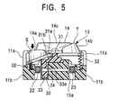
- each mechanical switch 13 comprises four resin key tops 14 arranged in four directions, a substantially cylindrical support member 31 supporting these key tops 14, and a switch 30 arranged at the bottom of the key tops 14. Further, the mechanical switch 13 is equipped with coil springs 32 elastically supporting part of the key tops 14.
- the key tops 14 consist of first key tops 14a and 14b arranged on the left-hand side and the right-hand side as seen in the drawing, a second key top 14c arranged behind them, and a second key top 14d (See Fig. 1).
- the first key tops 14a and 14b are used to adjust horizontal angular position, and the second key tops 14c and 14d are used to adjust vertical angular position.
- the support member 31 is equipped with a groove portion 31a supporting part of the key tops 14 and a protruding portion 31b formed on the substantially cylindrical side wall portion thereof. It is arranged on the back side of the central portion of the top plate 11c.
- the switch 30 is equipped with a movable portion 33 which can reciprocate and which is cylindrical, and a spring member (not shown) arranged at the bottom of a space 15c in which this movable portion 33 is arranged.
- the movable portion 33 is elastically supported by this spring member.
- the movable portion 33 is equipped with a window portion 34 extending at right angles through the side wall thereof, and a cutout portion 33a formed by cutting out in L-shape the end portion abutting the bottom surface of the key top 14 of the movable portion 33. A part of the movable portion 33 abuts the bottom surface of the key top 14, and the cutout portion 33a abuts the protruding portion 31b of the support member 31.
- the key top 14 When the first key top 14a of the mechanical switch 13 is depressed (as indicated by symbol S in the drawing), the key top 14 rotates against the resilient force of the coil spring 32 and the spring member using the groove portion 31a as a fulcrum, and the movable portion 33 is depressed, with the result that the window portion 34 of the movable portion 33 faces the third light guide 21.
- the depression of this key top 14a is canceled, the coil spring 32 and the spring member are restored to the former condition, and respectively push up the key top 14a and the movable portion 33 to the former positions (as indicated by symbol T in the drawing), the window portion 34 being detached from the light guide 21 to shield the light guide 21.
- a part of the key top 14a abuts the back surface of the top plate 11c, and the protruding portion 31b of the support member 31 abuts the step portion 33a of the movable portion 33, whereby detachment prevention is achieved.
- the motor-vehicle-mounted optical communication device 100 is equipped with the above-described compound optical switch 10 and a receiving section 40 for receiving light emitted from the compound optical switch 10, and comprises a light source (not shown) for constantly generating white light having a wide wavelength band, and the optical fibers 17 connecting the compound optical switch 10 and the receiving section 40 and transmitting white light to them.
- the mechanical switches 13 arranged in the third light guides 21a, 21b, 21c, and 21d respectively correspond to the first key top 14d, the second key top 14a, the first key top 14b, and the second key top 14c.
- the receiving section 40 comprises a linearly formed fourth light guide 44, third optical filters 41 inclined at 45 degrees, arranged at predetermined intervals and adapted to reflect light of specific wavelength bands, and photo detectors 42 adapted to convert the light reflected by the third optical filters 41 to electric signals.
- the third optical filters 41 there are arranged a filter D (which reflects orange light having a wavelength ⁇ 4 and allows other lights to be transmitted), a filter C (which reflects red light having a wavelength ⁇ 3 and allows other lights to be transmitted), a filter B (which reflects blue light having a wavelength ⁇ 2 and allows other lights to be transmitted), and a filter A (which reflects green light having a wavelength ⁇ 1 and allows other lights to be transmitted) in that order from the side nearest the mounting portion of the optical fiber 17.
- a filter D which reflects orange light having a wavelength ⁇ 4 and allows other lights to be transmitted
- a filter C which reflects red light having a wavelength ⁇ 3 and allows other lights to be transmitted
- a filter B which reflects blue light having a wavelength ⁇ 2 and allows other lights to be transmitted
- a filter A which reflects green light having a wavelength ⁇ 1 and allows other lights to be transmitted
- Fig. 6A is a diagram illustrating the operation when the compound optical switch 10 is in the OFF state
- Fig. 6B is a diagram illustrating the operation when it is in the ON state.
- the movable portions 33 of the mechanical switches 13 arranged in the third light guides 21a, 21b, 21c, and 21d cut off the specific light incident at right angles on the third light guides 21a, 21b, 21c, and 21d from the first optical filters 22, and the lights are not output to the second optical filters 23.
- the lights are not transmitted from the compound optical switch to the receiving section 40 through the optical fiber 17.
- the window portion 34 of the movable portion 33 moves to the third light guide 21b, so that blue light having a wavelength ⁇ 2 reflected by the first optical filter B is transmitted through the third light guide 21b through the window portion 34 and reflected at right angles by the second optical filter B. Then, the blue light having a wavelength ⁇ 2 reflected is allowed to be transmitted through the filter A and transmitted to the optical fiber 17 from the compound optical switch 10 before it impinges upon the receiving section 40.
- the blue light is allowed to be transmitted through the optical filters 41 (the filters D and C) in the fourth light guide 44, and reflected at right angles by the optical filter 41 (the optical filter B) before it is converted to an electric signal by the photo detector 42 arranged forward.
- a motor (not shown) causes the door mirror to move to the left by a predetermined angle in accordance with this electric signal.
- the compound optical switch 10 is mounted in the switch for operating the door mirror of the motor vehicle, and lights of specific wavelength bands are respectively in correspondence with the four key tops 14, whereby it is possible to move the door mirror vertically or horizontally to a predetermined angular position through an actuator such as a motor.
- a receiving section 45 is equipped with a case 45a, and a fiber inserting portion 18a formed perpendicularly to the side wall of the case 45a, and the optical fiber 17 is mounted and secured to this fiber inserting portion 18a.
- the receiving section 45 is equipped with a fifth light guide 46 formed in line with the extension 17x of the axis of the optical fiber inserting portion 18a, a sixth light guide 47 extending perpendicularly to the longitudinal direction of the fifth light guide 46 and branching off from near one end of the fiber inserting portion 18a, and a seventh light guide 48 branching off from the sixth light guide 47 so as to extend parallel to the fifth light guide 46. Further, there is formed an eighth light guide 49 branching off from the fifth light guide 46 and extending at right angles to the light guide 46 in a direction opposite to the sixth light guide 47.
- the end portion of the eighth light guide 49 is formed so as to extend through a side wall (the upper wall as seen in the drawing) of the case 45a.
- the end portions of the fifth and seventh light guides 46 and 48 are formed so as to extend through the side wall of the case 45a on the opposite side of the fiber inserting portion 18.
- the end portion of the sixth light guide 47 is formed so as to extend through a side wall (the lower wall as seen in the drawing) of the case 45a.
- Photo receptors 42 are mounted and secured to the positions of the case where these light guides extend through the walls.
- Flat fourth optical filters 50 are arranged obliquely at the branching point between the fifth light guide 46 and the sixth light guide 47, the branching point between the sixth light guide 47 and the seventh light guide 48, and the branching point between the fifth light guide 46 and the eighth light guide 49.
- the fourth optical filter 49 (filter E) arranged at the branching point between the fifth light guide 46 and the sixth light guide 47 reflects green light having a wavelength ⁇ 1 and blue light having a wavelength ⁇ 2, and allows other lights to be transmitted.
- the optical filter 49 (filter D) arranged at the branching point between the fifth light guide 46 and the eighth light guide 49 reflects orange light having a wavelength ⁇ 4, and allows lights of other wavelength bands to be transmitted.
- the optical filter 49 (filter B) arranged at the branching point between the sixth light guide 47 and the seventh light guide 48 reflects blue light having a wavelength ⁇ 2, and allows lights of other wavelength bands to be transmitted.
- Red light having a wavelength ⁇ 3 is transmitted through the two fourth optical filters E and D before it impinges upon the photo detector 42 arranged in the fifth light guide 46.
- blue light having a wavelength ⁇ 2 and orange light having a wavelength ⁇ 4 similarly impinge upon the photo detectors 42 arranged in the seventh light guide 48 and the eighth light guide 49, respectively.
- the fourth optical filters 50 (filters D, B and E) are combined to form the receiving section 45, whereby it is possible to perform the necessary adjustment of the angular position of the door mirror in the vertical and horizontal directions in correspondence with the four key switches 14 of the compound optical switch 10.
- the filter E which reflects (green and blue) lights of two wavelength bands and allows lights of other wavelength bands to be transmitted, it is possible to reduce the number of optical filters and the assembly is facilitated, whereby an improvement is achieved in terms of reliability.
- a compound optical switch comprising a common case, input and output side optical paths and a plurality of light guides connecting the optical paths which are arranged in the common case, switches provided in the light guides and adapted to selectively cut off or transmit introduced light, and a plurality of optical filters provided at the junction points of the input side optical path and the light guides and of the output side optical path and the light guides and adapted to reflect lights of different wavelength bands and allow other lights to be transmitted, whereby it is possible to guide predetermined light to each light guide in a single case with no wavelength bands overlapping each other. Further, a multi-step connection of the light guides is effected in a single package, whereby a reduction in the size of the compound optical switch is achieved.
- a compound optical switch comprising a case, a mechanical switch equipped with a plurality of key tops, first and second light guides opposed to each other, and a plurality of third light guides connecting the first and second light guides, wherein the mechanical switch is equipped with switches for cutting off or transmitting light introduced into the third light guides in accordance with the movement of the key tops, and wherein there are provided a plurality of optical filters arranged at the junction points of the first and third light guides and of the third and second light guides and adapted to reflect lights of predetermined different wavelength bands and to transmit other light, lights of predetermined wavelength bands incident on the third light guides being emitted to the second light guide through the switches corresponding to the key tops that are operated, so that lights are cut off or transmitted solely by turning ON/OFF the mechanical switch, whereby an improvement in durability and reliability is achieved without using electric contacts.
- an optical communication device comprising an optical fiber transmitting light of a wide wavelength band, a compound optical switch arranged through the intermediation of the optical fiber, and a receiving section, wherein the receiving section includes a plurality of optical filters for selectively demultiplexing lights of different predetermined wavelength bands transmitted through the optical fiber and photoreceptors for receiving the lights demultiplexed by the optical filters, so that it is possible to transmit lights of predetermined wavelength bands to the receiving section, where the lights are received, whereby it is possible to reliably drive the door mirror of an automobile, and it is possible to perform predetermined driving with higher reliability without causing incorrect operation of other electrical systems of the vehicle by electrical noise.
Applications Claiming Priority (2)
| Application Number | Priority Date | Filing Date | Title |
|---|---|---|---|
| JP19710098 | 1998-07-13 | ||
| JP10197100A JP2000028932A (ja) | 1998-07-13 | 1998-07-13 | 複合光スイッチ及びその複合光スイッチを用いた光通信装置 |
Publications (2)
| Publication Number | Publication Date |
|---|---|
| EP0973054A2 true EP0973054A2 (de) | 2000-01-19 |
| EP0973054A3 EP0973054A3 (de) | 2002-02-20 |
Family
ID=16368734
Family Applications (1)
| Application Number | Title | Priority Date | Filing Date |
|---|---|---|---|
| EP99304871A Withdrawn EP0973054A3 (de) | 1998-07-13 | 1999-06-22 | Komplexer optischer Schalter und diesen Schalter verwendendes optisches Kommunikationsgerät |
Country Status (2)
| Country | Link |
|---|---|
| EP (1) | EP0973054A3 (de) |
| JP (1) | JP2000028932A (de) |
Cited By (2)
| Publication number | Priority date | Publication date | Assignee | Title |
|---|---|---|---|---|
| EP0965869A2 (de) * | 1998-06-18 | 1999-12-22 | Alps Electric Co., Ltd. | Optischer Schalter und seine Verwendung in einem optischen Übertragungssystem |
| NL1034341C2 (nl) * | 2006-09-06 | 2009-02-03 | Wafermasters | Lichtbundelconditioneringseenheid. |
Citations (6)
| Publication number | Priority date | Publication date | Assignee | Title |
|---|---|---|---|---|
| US3953727A (en) * | 1974-01-18 | 1976-04-27 | Thomson-Csf | System for transmitting independent communication channels through a light-wave medium |
| JPS6060620A (ja) * | 1983-09-14 | 1985-04-08 | Toyo Denso Co Ltd | 光信号符号化装置 |
| JPS60133407A (ja) * | 1983-12-21 | 1985-07-16 | Honda Motor Co Ltd | 光スイツチ装置 |
| JPS61218013A (ja) * | 1985-03-25 | 1986-09-27 | キヤノン株式会社 | 光学式スイツチ |
| US4707057A (en) * | 1983-07-21 | 1987-11-17 | Honda Giken Kogyo Kabushiki Kaisha | Optical switching unit |
| US5175780A (en) * | 1988-12-29 | 1992-12-29 | Fuji Electric Co., Ltd. | Optical fiber switch |
-
1998
- 1998-07-13 JP JP10197100A patent/JP2000028932A/ja not_active Withdrawn
-
1999
- 1999-06-22 EP EP99304871A patent/EP0973054A3/de not_active Withdrawn
Patent Citations (6)
| Publication number | Priority date | Publication date | Assignee | Title |
|---|---|---|---|---|
| US3953727A (en) * | 1974-01-18 | 1976-04-27 | Thomson-Csf | System for transmitting independent communication channels through a light-wave medium |
| US4707057A (en) * | 1983-07-21 | 1987-11-17 | Honda Giken Kogyo Kabushiki Kaisha | Optical switching unit |
| JPS6060620A (ja) * | 1983-09-14 | 1985-04-08 | Toyo Denso Co Ltd | 光信号符号化装置 |
| JPS60133407A (ja) * | 1983-12-21 | 1985-07-16 | Honda Motor Co Ltd | 光スイツチ装置 |
| JPS61218013A (ja) * | 1985-03-25 | 1986-09-27 | キヤノン株式会社 | 光学式スイツチ |
| US5175780A (en) * | 1988-12-29 | 1992-12-29 | Fuji Electric Co., Ltd. | Optical fiber switch |
Non-Patent Citations (2)
| Title |
|---|
| PATENT ABSTRACTS OF JAPAN vol. 009, no. 195 (P-379), 13 August 1985 (1985-08-13) & JP 60 060620 A (TOUYOU DENSOU KK;OTHERS: 01), 8 April 1985 (1985-04-08) * |
| PATENT ABSTRACTS OF JAPAN vol. 009, no. 296 (P-407), 22 November 1985 (1985-11-22) & JP 60 133407 A (HONDA GIKEN KOGYO KK;OTHERS: 01), 16 July 1985 (1985-07-16) * |
Cited By (4)
| Publication number | Priority date | Publication date | Assignee | Title |
|---|---|---|---|---|
| EP0965869A2 (de) * | 1998-06-18 | 1999-12-22 | Alps Electric Co., Ltd. | Optischer Schalter und seine Verwendung in einem optischen Übertragungssystem |
| EP0965869A3 (de) * | 1998-06-18 | 2000-08-23 | Alps Electric Co., Ltd. | Optischer Schalter und seine Verwendung in einem optischen Übertragungssystem |
| US6297896B1 (en) | 1998-06-18 | 2001-10-02 | Alps Electric Co., Ltd. | Optical switch and optical communication system using the same |
| NL1034341C2 (nl) * | 2006-09-06 | 2009-02-03 | Wafermasters | Lichtbundelconditioneringseenheid. |
Also Published As
| Publication number | Publication date |
|---|---|
| EP0973054A3 (de) | 2002-02-20 |
| JP2000028932A (ja) | 2000-01-28 |
Similar Documents
| Publication | Publication Date | Title |
|---|---|---|
| US20010050928A1 (en) | MEMS-based selectable laser source | |
| EP0361368B1 (de) | Übertragungssystem für optische Signale | |
| CA2033696C (en) | Optical communication system having an improved protection line switching mechanism | |
| GB2196054A (en) | Drive apparatus of a roof structure for a vehicle | |
| EP0973054A2 (de) | Komplexer optischer Schalter und diesen Schalter verwendendes optisches Kommunikationsgerät | |
| CA2536579A1 (en) | Electrostatically driven latchable actuator system | |
| EP0823981B1 (de) | Durch eine bus versorgtes handbetätigtes integriertes anzeigelampe /kontakt/ kommunikationsmodul | |
| US7062174B2 (en) | Wavelength division multiplexing add-drop multiplexer using an optical tapped delay line | |
| US6297896B1 (en) | Optical switch and optical communication system using the same | |
| US6842555B2 (en) | Method and apparatus for optical switching with same side input and outputs | |
| US5031985A (en) | Optical switch system and apparatus | |
| US4715673A (en) | Optical switch | |
| CA1323225C (en) | Fiber optic control system | |
| JPH04213896A (ja) | ラックに挿入可能な装置用の光信号接続装置 | |
| US6800839B2 (en) | Device for the optoelectronic detection of switching positions of a switching element | |
| AU2003258200A1 (en) | Optical switch assembly | |
| EP1176741B1 (de) | Optische Kommunikationseinrichtung und ihr Steuerungsverfahren | |
| US6181847B1 (en) | Optical switch | |
| US5892301A (en) | Mechanical AND-member for mutually locking power switches | |
| KR101197996B1 (ko) | 파워 윈도우 스위치 모듈 | |
| EP0601310A1 (de) | Optischer Leitungsstecker und optische Überbrückungsverdrahtung | |
| US6282973B1 (en) | Selector for a vehicle transmission as well as switch module therefor | |
| EP0560459B1 (de) | Anordnung zur Feststellung der Lage eines beweglichen Körpers | |
| JP3256611B2 (ja) | 光情報伝送装置 | |
| EP0847214A2 (de) | Optischer Verteiler |
Legal Events
| Date | Code | Title | Description |
|---|---|---|---|
| PUAI | Public reference made under article 153(3) epc to a published international application that has entered the european phase |
Free format text: ORIGINAL CODE: 0009012 |
|
| AK | Designated contracting states |
Kind code of ref document: A2 Designated state(s): AT BE CH CY DE DK ES FI FR GB GR IE IT LI LU MC NL PT SE Kind code of ref document: A2 Designated state(s): DE GB |
|
| AX | Request for extension of the european patent |
Free format text: AL;LT;LV;MK;RO;SI |
|
| PUAL | Search report despatched |
Free format text: ORIGINAL CODE: 0009013 |
|
| AK | Designated contracting states |
Kind code of ref document: A3 Designated state(s): AT BE CH CY DE DK ES FI FR GB GR IE IT LI LU MC NL PT SE |
|
| AX | Request for extension of the european patent |
Free format text: AL;LT;LV;MK;RO;SI |
|
| 17P | Request for examination filed |
Effective date: 20020307 |
|
| 17Q | First examination report despatched |
Effective date: 20020618 |
|
| AKX | Designation fees paid |
Free format text: DE GB |
|
| STAA | Information on the status of an ep patent application or granted ep patent |
Free format text: STATUS: THE APPLICATION IS DEEMED TO BE WITHDRAWN |
|
| 18D | Application deemed to be withdrawn |
Effective date: 20041022 |