EP0973029A1 - Lineares Sauerstoffsensorsystem - Google Patents
Lineares Sauerstoffsensorsystem Download PDFInfo
- Publication number
- EP0973029A1 EP0973029A1 EP99113850A EP99113850A EP0973029A1 EP 0973029 A1 EP0973029 A1 EP 0973029A1 EP 99113850 A EP99113850 A EP 99113850A EP 99113850 A EP99113850 A EP 99113850A EP 0973029 A1 EP0973029 A1 EP 0973029A1
- Authority
- EP
- European Patent Office
- Prior art keywords
- signal
- vout
- circuit
- rcomp
- compensation
- Prior art date
- Legal status (The legal status is an assumption and is not a legal conclusion. Google has not performed a legal analysis and makes no representation as to the accuracy of the status listed.)
- Granted
Links
- 239000001301 oxygen Substances 0.000 title claims abstract description 26
- 229910052760 oxygen Inorganic materials 0.000 title claims abstract description 26
- QVGXLLKOCUKJST-UHFFFAOYSA-N atomic oxygen Chemical compound [O] QVGXLLKOCUKJST-UHFFFAOYSA-N 0.000 title claims abstract description 17
- 238000012360 testing method Methods 0.000 title abstract description 14
- 239000000203 mixture Substances 0.000 claims abstract description 29
- 239000007789 gas Substances 0.000 claims abstract description 20
- 238000002485 combustion reaction Methods 0.000 claims abstract description 12
- -1 oxygen ions Chemical class 0.000 claims abstract description 9
- 238000012937 correction Methods 0.000 claims abstract description 8
- 230000007246 mechanism Effects 0.000 claims abstract description 5
- 238000009792 diffusion process Methods 0.000 claims description 21
- 239000000567 combustion gas Substances 0.000 claims description 10
- 230000002596 correlated effect Effects 0.000 claims description 9
- 238000012545 processing Methods 0.000 claims description 7
- 230000000875 corresponding effect Effects 0.000 claims description 3
- 230000000694 effects Effects 0.000 claims description 2
- 238000006243 chemical reaction Methods 0.000 claims 3
- 230000003321 amplification Effects 0.000 claims 1
- 230000004927 fusion Effects 0.000 claims 1
- 150000002500 ions Chemical class 0.000 claims 1
- 238000003199 nucleic acid amplification method Methods 0.000 claims 1
- 238000005086 pumping Methods 0.000 description 7
- 239000000446 fuel Substances 0.000 description 6
- 230000009471 action Effects 0.000 description 4
- 238000004519 manufacturing process Methods 0.000 description 3
- 238000010438 heat treatment Methods 0.000 description 2
- 238000000034 method Methods 0.000 description 2
- 230000008569 process Effects 0.000 description 2
- 230000008646 thermal stress Effects 0.000 description 2
- 230000008901 benefit Effects 0.000 description 1
- 230000003197 catalytic effect Effects 0.000 description 1
- 230000008859 change Effects 0.000 description 1
- 230000001143 conditioned effect Effects 0.000 description 1
- 230000009977 dual effect Effects 0.000 description 1
- 238000011990 functional testing Methods 0.000 description 1
- 238000009434 installation Methods 0.000 description 1
- 238000012423 maintenance Methods 0.000 description 1
- 238000005259 measurement Methods 0.000 description 1
- 238000011084 recovery Methods 0.000 description 1
- 239000000126 substance Substances 0.000 description 1
- 230000009466 transformation Effects 0.000 description 1
- 238000011144 upstream manufacturing Methods 0.000 description 1
Images

Classifications
-
- G—PHYSICS
- G01—MEASURING; TESTING
- G01N—INVESTIGATING OR ANALYSING MATERIALS BY DETERMINING THEIR CHEMICAL OR PHYSICAL PROPERTIES
- G01N27/00—Investigating or analysing materials by the use of electric, electrochemical, or magnetic means
- G01N27/26—Investigating or analysing materials by the use of electric, electrochemical, or magnetic means by investigating electrochemical variables; by using electrolysis or electrophoresis
- G01N27/416—Systems
- G01N27/417—Systems using cells, i.e. more than one cell and probes with solid electrolytes
- G01N27/4175—Calibrating or checking the analyser
Definitions
- the present invention relates to an oxygen linear sensor test arrangement.
- the present invention relates to the oxygen linear sensor test arrangement known as the "UEGO” sensor (universal exhaust gas oxygen sensor), to which the following makes explicit reference though without loss of its general nature.
- UEGO oxygen linear sensor test arrangement
- the present invention is of advantage in the automotive field, where it is known to use a UEGO sensor, located along the exhaust manifold of an internal combustion engine, to obtain information concerning the composition of the exhaust gases.
- the UEGO sensor has two electrolytic cells responding to oxygen ions, and a diffusion chamber placed between the actual cells and able to receive part of the combustion gases at the outlet from the engine.
- the UEGO sensor provides for the use of a test arrangement which is connected to the sensor itself by means of a connector, and is able to pilot electrically the electrolytic cells to produce a test action on the sensor itself.
- control means is designed to provide an oxygen ions graining mechanism from the diffusion chamber to atmosphere and vice versa, in order to obtain within the actual chamber an exhaust gas composition equal to that which would obtain in the event of the air/petrol ratio of the mixture fed to the engine becoming stoichiometric, i.e. equal to 14.57.
- the intensity of the test action is the information on the basis whereof the test arrangement generates the output of a Vout signal representative of the composition of the exhaust gases proceeding from the engine.
- the said Vout signal is proportional to the quantity of oxygen present within the exhaust gas and consequently, is indicative of the air stroke/petrol ratio of the mixture fed to the engine.
- test arrangements before installation on the vehicle, need to be connected to a compensation resistance able to compensate eventual spreads of the piloting current.
- the said compensation resistance is inserted between two connections of the said connector, and cooperating with the test arrangement, actively intervenes in the generation of the Vout signal.
- the compensation resistance being located within the engine space, is subject to heavy thermal stresses during operation of the engine.
- the purpose of the present invention is to achieve an oxygen linear sensor test arrangement, which provides a solution to the aforesaid problem. According to the present invention an oxygen linear sensor test arrangement of the type described in claim 1 is achieved.
- the reference 1 indicates a UEGO sensor of known type able to be located along the exhaust manifold 2 of an internal combustion engine 3 to obtain information concerning the stoichiometric composition of combustion gases, and finally concerning the A/F (air/fuel) ratio of the mixture supplied to the engine.
- the senor 1 is arranged upstream of a catalytic converter 4 able to reduce the polluting substances present in the combustion gases before they are ejected to external atmosphere.
- the engine 3 has a fuel supply arrangement 5 (for instance using petrol) to the cylinders (not illustrated), and an ignition arrangement 6 to ignite the combustion processes within the cylinders.
- the engine 3 is controlled by an electronic central control unit 7 (illustrated diagrammatically) which controls the supply arrangement 5 to regulate the quantity of fuel to be injected into the cylinders, and controls the ignition arrangement 6 to regulate the ignition timing of combustion within the cylinders.
- the electronic control unit 7 comprises an electronic control arrangement 8 for the UEGO sensor 1 which is connected to the sensor 1 by means of a connector 9.
- the control arrangement 8 is able to process the information proceeding from the sensor 1 to generate an output signal Vout, which according to the present invention is a digital signal correlated with the quantity of oxygen present in the combustion gases and correlated with the A/F ratio.
- the Vout signal is the digital-converted result of a proportional analogue signal corresponding with the quantity of oxygen within the combustion gases.
- the measured A/F ratio is greater than the A/F stoichiometric ratio and the mixture supplied to the engine 3 is said to be lean
- the value of parameter ⁇ m is lower than unity ( ⁇ m ⁇ 1) the measured A/F ratio is lower than the A/F stoichiometric ratio and the mixture supplied to the engine 3 is said to be rich.
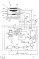
- Figure 2 illustrates in greater detail the connection of the UEGO sensor 1 to the control arrangement 8 by means of the connector 9.
- the senor 1 has two electrolytic cells 11 and 12 responding to oxygen ions, respectively termed “Vs sensing cell” and “pumping cell Ip", and a diffusion chamber 13 interposed between the cells 11 and 12 and able to receive the exhaust gas.
- the sensor 1 also has a reference chamber 14, which is located on the opposite side of the diffusion chamber 13 in relation to cell 11, and is in a stoichiometric condition, i.e. presenting an oxygen level equal to that which the exhaust gas would have in the event of the A/F ratio of the mixture fed to the engine being stoichiometric.
- the cell 11 presents at its heads a pair of electrodes 11a and 11b electrically connected to respective connections 9a, 9b of the connector 9.
- the cell 12 has at its heads a pair of electrodes 12a and 12b, of which the electrode 12a is connected electrically to the electrode 11b of cell 11, whereas electrode 12b is connected to a connection 9c of the connector 9.
- the control arrangement 8 has the dual function of electrical supply to the sensor 1 and ensuring a retroactive control action designed to modify compositionof the gas in the diffusion chamber 13.
- the arrangement 8 is able to pilot a pumping current Ip to the electrode 12b of cell 12 to achieve an oxygen ions draining mechanism in the diffusion chamber 13 out to atmosphere (and vice-versa) in such a way as to achieve a stoichiometric level within the diffusion chamber 13.
- the intensity of the control action that is to say the intensity of the pumping current Iprequired to maintain a stoichiometric level within the diffusion chamber 13 is the information on the basis whereof the control arrangement 8 generates the output of Vout signal.
- the control arrangement 8 comprises an amplifier 15 which is connected to the input of connections 9a and 9b of the connector 9 to receive the Vd signal (voltage), and is able to supply the amplified Vd signal to a subtracter input 17a of a summation node 17.
- the amplified signal Vd assumes values of around 450mV whenever within the diffusion chamber 13 there are gases originating from the combustion of a stoichiometric mixture, and in the meantime assumes values greater than 450mV (or respectively lower than 450 mV) when the gases originate from the combustion of a rich mixture (or respectively lean mixture).
- the summation node 17 has a summation input 17b to which is supplied a reference signal Vd ref , which represents the reference (or set point) for the amplified Vd signal, and is equal to the amplified value of the signal Vd which is present at the heads of the cell 12 in the event that the exhaust gases emitted from the diffusion chamber 13 originate from the combustion of a stoichiometric mixture.
- Vd ref represents the reference (or set point) for the amplified Vd signal
- the node 17 generates on output an error signal Verr, which is defined by the difference between the reference signal Vdrif and the amplified Vd signal, and is represented above the error between the voltage in the heads of cell 11 in the event of stoichiometric conditions and that which effectively is recorded at the heads of cell 12.
- the error signal Verr is supplied to a processing circuit 19 able to process it to provide on output a correction signal Vcorr.
- the processing circuit 19 is defined by a PID controller of known type able to effect a proportional integral derivative transformation (PID) of the Verr signal to generate the Vcorr signal.
- PID proportional integral derivative transformation
- the Vcorr correction signal is supplied to a pilot circuit 22 (of known type), which, on the basis of the Vcorr signal, regulates the intensity of the pumping current Ip to be fed to cell 12.
- the Vcorr signal is the input on the basis whereof the pilot circuit 22 corrects the current Ip so that the cell 12 drains the oxygen ions from the diffusion chamber 13 to atmosphere (or vice versa) to originate stoichiometric conditions in chamber 13.
- the pilot circuit 22 is represented by a voltage/current converter of known type able to convert the Vcorr voltage signal into a corresponding current Ip to be supplied to cell 12.
- the error signal Verr is lower than zero, and the PID controls the pilot circuit 22 so that within cell 12 a current Ip is piloted such as to generate a flow of oxygen ions from atmosphere towards the diffusion chamber 13.
- the pilot circuit 22 cooperates with an output circuit 23 which in a known manner, converts the pumping current Ip into an output Vout1 signal correlated with the composition of the combustion gases present in the discharge duct 2, or with the quantity of oxygen present in the gases leaving the engine 3.
- the said output circuit 23 is thus able to convert the pause supplied by the control arrangement 8 to maintain a stoichiometric condition in the diffusion chamber 13, into a Vout 1 signal, which is converted by analogue/digital converter 24 into a digital signal Vout1 which saving a correction explained below, represents the output Vout signal from the arrangement 8.
- the connector 9 has two further connections 9d, 9e ( Figure 2) between which a compensation resistance 25 is connected, and is able to allow compensation of eventual spreads in the pumping current Ip so that the Vout signal always remains indicative of the effective composition of the exhaust gases leaving the engine 3.
- the nominal value of the compensation resistance 25 is indicated for the purposes of manufacture of the sensor 1 and of the control arrangement 8 following functional tests carried out to check the efficiency of the sensor itself.
- the control arrangement comprises a circuit 26 to acquire the resistance 25, which is connected to connections 9d and 9e, and cooperates with a storage circuit 27 (of known type) able to allow permanent storage of a parameter Rcomp correlated with the compensation resistance 25.
- the storage circuit 27 is able to store the Rcomp parameter according to the engine ignition so that throughout the operation of the engine it is possible for compensation of the spreads in current Ip always using the same parameter value Rcomp.
- connection 9e is supplied from resistance 25 with battery voltage Vbat, allows the connection 9d to be connected to the input 28a of an analog/digital converter 28 by means of a voltage splitter 29.
- the splitter 29 has a resistance R1 connected between the connection 9d and input 28a, and a resistance R2 connected between the input 28a itself and earth 30.
- the analog/digital converter 28 thus receives on input a voltage Vr 2 correlated with the value of the compensation resistance 25, and is connected on output to a calculator block 31 also receiving on input voltage from the battery Vbat acquired by way of an analog/digital converter 32.
- the calculator block 31 thus supplies the Rcomp parameter to storage circuit 27.
- the stored Rcomp parameter is supplied to an electronic panel 33 of known type, which is able to supply on output a correction Kcorr parameter suitable for application to signal Vout1 to obtain the output signal Vout of arrangement 8.
- Rcomp parameter which in the example illustrated here occurs following engine ignition, allows the Vout 1 signal to be corrected always with the same Kcorr parameter, and therefore, obtaining on output from the arrangement 8 a Vout signal not conditioned by changes in the compensation resistance 25.
- the senor 1 also has a heating resistance 35 connected between the connection 9e and a further connection 9f of the connector 9 and able to allow the maintenance of the sensor temperature within a predetermined temperature range (generally around 780°c).
- the control arrangement 8 provides for a pilot unit (known and not illustrated) able to regulate the current passing through the heating resistance 35 to rapidly take the temperature of the sensor within the said range on ignition of the engine and to maintain the temperature of the sensor within that range throughout normal operation of the engine.
Landscapes
- Chemical & Material Sciences (AREA)
- Life Sciences & Earth Sciences (AREA)
- Health & Medical Sciences (AREA)
- Biochemistry (AREA)
- General Physics & Mathematics (AREA)
- Electrochemistry (AREA)
- Physics & Mathematics (AREA)
- Analytical Chemistry (AREA)
- Molecular Biology (AREA)
- General Health & Medical Sciences (AREA)
- Chemical Kinetics & Catalysis (AREA)
- Immunology (AREA)
- Pathology (AREA)
- Combined Controls Of Internal Combustion Engines (AREA)
- Electrical Control Of Air Or Fuel Supplied To Internal-Combustion Engine (AREA)
- Measuring Oxygen Concentration In Cells (AREA)
- Measurement Of The Respiration, Hearing Ability, Form, And Blood Characteristics Of Living Organisms (AREA)
- Investigating Or Analyzing Materials By The Use Of Magnetic Means (AREA)
- Measurement And Recording Of Electrical Phenomena And Electrical Characteristics Of The Living Body (AREA)
Applications Claiming Priority (2)
| Application Number | Priority Date | Filing Date | Title |
|---|---|---|---|
| ITBO980434 | 1998-07-16 | ||
| IT1998BO000434A IT1306315B1 (it) | 1998-07-16 | 1998-07-16 | Dispositivo di controllo di una sonda lineare di ossigeno |
Publications (2)
| Publication Number | Publication Date |
|---|---|
| EP0973029A1 true EP0973029A1 (de) | 2000-01-19 |
| EP0973029B1 EP0973029B1 (de) | 2008-06-11 |
Family
ID=11343306
Family Applications (1)
| Application Number | Title | Priority Date | Filing Date |
|---|---|---|---|
| EP99113850A Expired - Lifetime EP0973029B1 (de) | 1998-07-16 | 1999-07-15 | Lineares Sauerstoffsensorsystem |
Country Status (7)
| Country | Link |
|---|---|
| US (1) | US6231735B1 (de) |
| EP (1) | EP0973029B1 (de) |
| JP (1) | JP4531885B2 (de) |
| BR (1) | BR9904564A (de) |
| DE (1) | DE69938886D1 (de) |
| ES (1) | ES2308825T3 (de) |
| IT (1) | IT1306315B1 (de) |
Cited By (2)
| Publication number | Priority date | Publication date | Assignee | Title |
|---|---|---|---|---|
| US7052596B2 (en) * | 2000-06-16 | 2006-05-30 | Siemens Aktiengesellschaft | Linear lambda probe evaluation circuit |
| US9429541B2 (en) | 2010-03-02 | 2016-08-30 | Ngk Spark Plug Co., Ltd. | Gas sensor element, gas sensor and control system of gas sensor |
Families Citing this family (4)
| Publication number | Priority date | Publication date | Assignee | Title |
|---|---|---|---|---|
| JP3880507B2 (ja) * | 2001-12-27 | 2007-02-14 | 株式会社日本自動車部品総合研究所 | ガス濃度検出装置 |
| JP3885705B2 (ja) * | 2002-10-10 | 2007-02-28 | 株式会社デンソー | ガス濃度検出装置 |
| US10746118B1 (en) * | 2019-07-02 | 2020-08-18 | Delphi Technologies Ip Limited | Compensator circuitry and method for an oxygen sensor |
| CN112305145B (zh) * | 2020-10-30 | 2022-07-19 | 中国民用航空总局第二研究所 | 一种燃烧蔓延试验装置及其试验方法 |
Citations (4)
| Publication number | Priority date | Publication date | Assignee | Title |
|---|---|---|---|---|
| JPS58162858A (ja) * | 1982-03-23 | 1983-09-27 | Hitachi Ltd | 酸素濃度検出器 |
| US4532013A (en) * | 1981-04-16 | 1985-07-30 | Robert Bosch Gmbh | Method for monitoring operation of a current-limiting type gas sensor |
| US5524472A (en) * | 1993-12-30 | 1996-06-11 | Robert Bosch Gmbh | Evaluating arrangement for the signal of an oxygen probe |
| US5558752A (en) * | 1995-04-28 | 1996-09-24 | General Motors Corporation | Exhaust gas sensor diagnostic |
Family Cites Families (6)
| Publication number | Priority date | Publication date | Assignee | Title |
|---|---|---|---|---|
| JPH0680426B2 (ja) * | 1984-10-22 | 1994-10-12 | 株式会社日立製作所 | 空燃比検出器 |
| JPH0727391Y2 (ja) * | 1986-02-04 | 1995-06-21 | 本田技研工業株式会社 | 内燃エンジンの空燃比制御装置 |
| JPH0635955B2 (ja) * | 1986-07-30 | 1994-05-11 | 三菱自動車工業株式会社 | 空燃比検出装置 |
| JPH07117526B2 (ja) * | 1987-12-14 | 1995-12-18 | 本田技研工業株式会社 | 酸素濃度検出装置 |
| JPH07119741B2 (ja) * | 1988-06-30 | 1995-12-20 | 本田技研工業株式会社 | 比例型排気濃度センサにおける出力補正方法 |
| JP2788511B2 (ja) * | 1989-11-15 | 1998-08-20 | 日本碍子株式会社 | 酸素濃度検出器の処理方法 |
-
1998
- 1998-07-16 IT IT1998BO000434A patent/IT1306315B1/it active
-
1999
- 1999-07-15 EP EP99113850A patent/EP0973029B1/de not_active Expired - Lifetime
- 1999-07-15 DE DE69938886T patent/DE69938886D1/de not_active Expired - Lifetime
- 1999-07-15 ES ES99113850T patent/ES2308825T3/es not_active Expired - Lifetime
- 1999-07-16 JP JP20335899A patent/JP4531885B2/ja not_active Expired - Fee Related
- 1999-07-16 BR BR9904564-8A patent/BR9904564A/pt not_active Application Discontinuation
- 1999-07-16 US US09/354,170 patent/US6231735B1/en not_active Expired - Lifetime
Patent Citations (4)
| Publication number | Priority date | Publication date | Assignee | Title |
|---|---|---|---|---|
| US4532013A (en) * | 1981-04-16 | 1985-07-30 | Robert Bosch Gmbh | Method for monitoring operation of a current-limiting type gas sensor |
| JPS58162858A (ja) * | 1982-03-23 | 1983-09-27 | Hitachi Ltd | 酸素濃度検出器 |
| US5524472A (en) * | 1993-12-30 | 1996-06-11 | Robert Bosch Gmbh | Evaluating arrangement for the signal of an oxygen probe |
| US5558752A (en) * | 1995-04-28 | 1996-09-24 | General Motors Corporation | Exhaust gas sensor diagnostic |
Non-Patent Citations (1)
| Title |
|---|
| PATENT ABSTRACTS OF JAPAN vol. 7, no. 290 (P - 245) 24 December 1983 (1983-12-24) * |
Cited By (3)
| Publication number | Priority date | Publication date | Assignee | Title |
|---|---|---|---|---|
| US7052596B2 (en) * | 2000-06-16 | 2006-05-30 | Siemens Aktiengesellschaft | Linear lambda probe evaluation circuit |
| US9429541B2 (en) | 2010-03-02 | 2016-08-30 | Ngk Spark Plug Co., Ltd. | Gas sensor element, gas sensor and control system of gas sensor |
| DE102011001028B4 (de) | 2010-03-02 | 2022-01-20 | Ngk Spark Plug Co., Ltd. | Gassensorelement, Gassensor und Kontrollsystem eines Gassensors |
Also Published As
| Publication number | Publication date |
|---|---|
| US6231735B1 (en) | 2001-05-15 |
| BR9904564A (pt) | 2000-10-03 |
| ES2308825T3 (es) | 2008-12-01 |
| DE69938886D1 (de) | 2008-07-24 |
| JP2000081415A (ja) | 2000-03-21 |
| ITBO980434A1 (it) | 2000-01-16 |
| JP4531885B2 (ja) | 2010-08-25 |
| EP0973029B1 (de) | 2008-06-11 |
| IT1306315B1 (it) | 2001-06-04 |
Similar Documents
| Publication | Publication Date | Title |
|---|---|---|
| US5036819A (en) | Control system for the air/fuel ratio of an internal combustion engine | |
| US6295862B1 (en) | Gas concentration measuring apparatus compensating for error component of output signal | |
| US9068937B2 (en) | Method and device for examining an exhaust gas sensor | |
| US7802463B2 (en) | Sensor control device and air fuel ratio detecting apparatus | |
| EP3006930A1 (de) | Gassensorsteuerungsvorrichtung | |
| CN103711601A (zh) | 用于识别电压-拉姆达-特性曲线的电压偏移的方法和控制单元 | |
| US6334352B1 (en) | Control device for a linear oxygen sensor | |
| GB2256929A (en) | Compensating output of air/fuel ratio sensor for variation in sensitivity to oxygen | |
| US7964073B2 (en) | Air fuel ratio detection apparatus | |
| US6231735B1 (en) | Oxygen linear sensor test arrangement | |
| US6223735B1 (en) | Control method for an oxygen linear sensor | |
| US20070272551A1 (en) | Gas sensor interface device and gas sensor system | |
| JP2006527843A (ja) | 複数の排ガス成分を測定するための装置と方法 | |
| US10746118B1 (en) | Compensator circuitry and method for an oxygen sensor | |
| US6093294A (en) | Gas sensor and gas concentration controller | |
| JP6536485B2 (ja) | 異常判別装置 | |
| JP2007315943A (ja) | ガス濃度検出装置 | |
| US12345600B2 (en) | Method for self-balancing of a lambda sensor and exhaust gas system | |
| US20240410304A1 (en) | Method for operating a drive device and corresponding drive device | |
| US6716326B2 (en) | Circuit arrangement for operating an exhaust-gas probe | |
| JP2010014562A (ja) | 空燃比検出装置 | |
| US20030101796A1 (en) | Device for operating a linear lambda probe | |
| US9529019B2 (en) | Impedance detector for oxygen concentration sensor element | |
| US12618799B2 (en) | Gas sensor and method of identifying deviation of reference potential of the same | |
| US20020014222A1 (en) | Thermal type air flow meter |
Legal Events
| Date | Code | Title | Description |
|---|---|---|---|
| PUAI | Public reference made under article 153(3) epc to a published international application that has entered the european phase |
Free format text: ORIGINAL CODE: 0009012 |
|
| AK | Designated contracting states |
Kind code of ref document: A1 Designated state(s): DE ES FR GB SE |
|
| AX | Request for extension of the european patent |
Free format text: AL;LT;LV;MK;RO;SI |
|
| 17P | Request for examination filed |
Effective date: 20000110 |
|
| AKX | Designation fees paid |
Free format text: DE ES FR GB SE |
|
| GRAP | Despatch of communication of intention to grant a patent |
Free format text: ORIGINAL CODE: EPIDOSNIGR1 |
|
| GRAS | Grant fee paid |
Free format text: ORIGINAL CODE: EPIDOSNIGR3 |
|
| RAP1 | Party data changed (applicant data changed or rights of an application transferred) |
Owner name: MAGNETI MARELLI POWERTRAIN S.P.A. |
|
| GRAA | (expected) grant |
Free format text: ORIGINAL CODE: 0009210 |
|
| RAP1 | Party data changed (applicant data changed or rights of an application transferred) |
Owner name: MAGNETI MARELLI POWERTRAIN S.P.A. |
|
| AK | Designated contracting states |
Kind code of ref document: B1 Designated state(s): DE ES FR GB SE |
|
| REG | Reference to a national code |
Ref country code: GB Ref legal event code: FG4D |
|
| REF | Corresponds to: |
Ref document number: 69938886 Country of ref document: DE Date of ref document: 20080724 Kind code of ref document: P |
|
| REG | Reference to a national code |
Ref country code: SE Ref legal event code: TRGR |
|
| REG | Reference to a national code |
Ref country code: ES Ref legal event code: FG2A Ref document number: 2308825 Country of ref document: ES Kind code of ref document: T3 |
|
| PLBE | No opposition filed within time limit |
Free format text: ORIGINAL CODE: 0009261 |
|
| STAA | Information on the status of an ep patent application or granted ep patent |
Free format text: STATUS: NO OPPOSITION FILED WITHIN TIME LIMIT |
|
| 26N | No opposition filed |
Effective date: 20090312 |
|
| PGFP | Annual fee paid to national office [announced via postgrant information from national office to epo] |
Ref country code: ES Payment date: 20090727 Year of fee payment: 11 |
|
| PGFP | Annual fee paid to national office [announced via postgrant information from national office to epo] |
Ref country code: SE Payment date: 20090727 Year of fee payment: 11 Ref country code: GB Payment date: 20090728 Year of fee payment: 11 |
|
| GBPC | Gb: european patent ceased through non-payment of renewal fee |
Effective date: 20100715 |
|
| PG25 | Lapsed in a contracting state [announced via postgrant information from national office to epo] |
Ref country code: GB Free format text: LAPSE BECAUSE OF NON-PAYMENT OF DUE FEES Effective date: 20100715 |
|
| REG | Reference to a national code |
Ref country code: ES Ref legal event code: FD2A Effective date: 20110818 |
|
| PG25 | Lapsed in a contracting state [announced via postgrant information from national office to epo] |
Ref country code: ES Free format text: LAPSE BECAUSE OF NON-PAYMENT OF DUE FEES Effective date: 20100716 |
|
| PG25 | Lapsed in a contracting state [announced via postgrant information from national office to epo] |
Ref country code: SE Free format text: LAPSE BECAUSE OF NON-PAYMENT OF DUE FEES Effective date: 20100716 |
|
| REG | Reference to a national code |
Ref country code: FR Ref legal event code: PLFP Year of fee payment: 18 |
|
| REG | Reference to a national code |
Ref country code: FR Ref legal event code: PLFP Year of fee payment: 19 |
|
| REG | Reference to a national code |
Ref country code: FR Ref legal event code: PLFP Year of fee payment: 20 |
|
| PGFP | Annual fee paid to national office [announced via postgrant information from national office to epo] |
Ref country code: FR Payment date: 20180621 Year of fee payment: 20 |
|
| PGFP | Annual fee paid to national office [announced via postgrant information from national office to epo] |
Ref country code: DE Payment date: 20180620 Year of fee payment: 20 |
|
| REG | Reference to a national code |
Ref country code: DE Ref legal event code: R071 Ref document number: 69938886 Country of ref document: DE |