EP0972874B1 - Washing Machine - Google Patents
Washing Machine Download PDFInfo
- Publication number
- EP0972874B1 EP0972874B1 EP98309862A EP98309862A EP0972874B1 EP 0972874 B1 EP0972874 B1 EP 0972874B1 EP 98309862 A EP98309862 A EP 98309862A EP 98309862 A EP98309862 A EP 98309862A EP 0972874 B1 EP0972874 B1 EP 0972874B1
- Authority
- EP
- European Patent Office
- Prior art keywords
- weight
- hall element
- output voltage
- tub
- sensing
- Prior art date
- Legal status (The legal status is an assumption and is not a legal conclusion. Google has not performed a legal analysis and makes no representation as to the accuracy of the status listed.)
- Expired - Lifetime
Links
Images


Classifications
-
- D—TEXTILES; PAPER
- D06—TREATMENT OF TEXTILES OR THE LIKE; LAUNDERING; FLEXIBLE MATERIALS NOT OTHERWISE PROVIDED FOR
- D06F—LAUNDERING, DRYING, IRONING, PRESSING OR FOLDING TEXTILE ARTICLES
- D06F39/00—Details of washing machines not specific to a single type of machines covered by groups D06F9/00 - D06F27/00
- D06F39/08—Liquid supply or discharge arrangements
- D06F39/087—Water level measuring or regulating devices
-
- D—TEXTILES; PAPER
- D06—TREATMENT OF TEXTILES OR THE LIKE; LAUNDERING; FLEXIBLE MATERIALS NOT OTHERWISE PROVIDED FOR
- D06F—LAUNDERING, DRYING, IRONING, PRESSING OR FOLDING TEXTILE ARTICLES
- D06F34/00—Details of control systems for washing machines, washer-dryers or laundry dryers
- D06F34/14—Arrangements for detecting or measuring specific parameters
- D06F34/16—Imbalance
-
- D—TEXTILES; PAPER
- D06—TREATMENT OF TEXTILES OR THE LIKE; LAUNDERING; FLEXIBLE MATERIALS NOT OTHERWISE PROVIDED FOR
- D06F—LAUNDERING, DRYING, IRONING, PRESSING OR FOLDING TEXTILE ARTICLES
- D06F34/00—Details of control systems for washing machines, washer-dryers or laundry dryers
- D06F34/14—Arrangements for detecting or measuring specific parameters
- D06F34/18—Condition of the laundry, e.g. nature or weight
-
- D—TEXTILES; PAPER
- D06—TREATMENT OF TEXTILES OR THE LIKE; LAUNDERING; FLEXIBLE MATERIALS NOT OTHERWISE PROVIDED FOR
- D06F—LAUNDERING, DRYING, IRONING, PRESSING OR FOLDING TEXTILE ARTICLES
- D06F2103/00—Parameters monitored or detected for the control of domestic laundry washing machines, washer-dryers or laundry dryers
- D06F2103/02—Characteristics of laundry or load
- D06F2103/04—Quantity, e.g. weight or variation of weight
-
- D—TEXTILES; PAPER
- D06—TREATMENT OF TEXTILES OR THE LIKE; LAUNDERING; FLEXIBLE MATERIALS NOT OTHERWISE PROVIDED FOR
- D06F—LAUNDERING, DRYING, IRONING, PRESSING OR FOLDING TEXTILE ARTICLES
- D06F2103/00—Parameters monitored or detected for the control of domestic laundry washing machines, washer-dryers or laundry dryers
- D06F2103/14—Supply, recirculation or draining of washing liquid
-
- D—TEXTILES; PAPER
- D06—TREATMENT OF TEXTILES OR THE LIKE; LAUNDERING; FLEXIBLE MATERIALS NOT OTHERWISE PROVIDED FOR
- D06F—LAUNDERING, DRYING, IRONING, PRESSING OR FOLDING TEXTILE ARTICLES
- D06F2103/00—Parameters monitored or detected for the control of domestic laundry washing machines, washer-dryers or laundry dryers
- D06F2103/18—Washing liquid level
-
- D—TEXTILES; PAPER
- D06—TREATMENT OF TEXTILES OR THE LIKE; LAUNDERING; FLEXIBLE MATERIALS NOT OTHERWISE PROVIDED FOR
- D06F—LAUNDERING, DRYING, IRONING, PRESSING OR FOLDING TEXTILE ARTICLES
- D06F2103/00—Parameters monitored or detected for the control of domestic laundry washing machines, washer-dryers or laundry dryers
- D06F2103/26—Imbalance; Noise level
-
- D—TEXTILES; PAPER
- D06—TREATMENT OF TEXTILES OR THE LIKE; LAUNDERING; FLEXIBLE MATERIALS NOT OTHERWISE PROVIDED FOR
- D06F—LAUNDERING, DRYING, IRONING, PRESSING OR FOLDING TEXTILE ARTICLES
- D06F2103/00—Parameters monitored or detected for the control of domestic laundry washing machines, washer-dryers or laundry dryers
- D06F2103/38—Time, e.g. duration
-
- D—TEXTILES; PAPER
- D06—TREATMENT OF TEXTILES OR THE LIKE; LAUNDERING; FLEXIBLE MATERIALS NOT OTHERWISE PROVIDED FOR
- D06F—LAUNDERING, DRYING, IRONING, PRESSING OR FOLDING TEXTILE ARTICLES
- D06F2103/00—Parameters monitored or detected for the control of domestic laundry washing machines, washer-dryers or laundry dryers
- D06F2103/44—Current or voltage
-
- D—TEXTILES; PAPER
- D06—TREATMENT OF TEXTILES OR THE LIKE; LAUNDERING; FLEXIBLE MATERIALS NOT OTHERWISE PROVIDED FOR
- D06F—LAUNDERING, DRYING, IRONING, PRESSING OR FOLDING TEXTILE ARTICLES
- D06F2105/00—Systems or parameters controlled or affected by the control systems of washing machines, washer-dryers or laundry dryers
- D06F2105/02—Water supply
-
- D—TEXTILES; PAPER
- D06—TREATMENT OF TEXTILES OR THE LIKE; LAUNDERING; FLEXIBLE MATERIALS NOT OTHERWISE PROVIDED FOR
- D06F—LAUNDERING, DRYING, IRONING, PRESSING OR FOLDING TEXTILE ARTICLES
- D06F2105/00—Systems or parameters controlled or affected by the control systems of washing machines, washer-dryers or laundry dryers
- D06F2105/08—Draining of washing liquids
-
- D—TEXTILES; PAPER
- D06—TREATMENT OF TEXTILES OR THE LIKE; LAUNDERING; FLEXIBLE MATERIALS NOT OTHERWISE PROVIDED FOR
- D06F—LAUNDERING, DRYING, IRONING, PRESSING OR FOLDING TEXTILE ARTICLES
- D06F2105/00—Systems or parameters controlled or affected by the control systems of washing machines, washer-dryers or laundry dryers
- D06F2105/52—Changing sequence of operational steps; Carrying out additional operational steps; Modifying operational steps, e.g. by extending duration of steps
-
- D—TEXTILES; PAPER
- D06—TREATMENT OF TEXTILES OR THE LIKE; LAUNDERING; FLEXIBLE MATERIALS NOT OTHERWISE PROVIDED FOR
- D06F—LAUNDERING, DRYING, IRONING, PRESSING OR FOLDING TEXTILE ARTICLES
- D06F2105/00—Systems or parameters controlled or affected by the control systems of washing machines, washer-dryers or laundry dryers
- D06F2105/58—Indications or alarms to the control system or to the user
-
- D—TEXTILES; PAPER
- D06—TREATMENT OF TEXTILES OR THE LIKE; LAUNDERING; FLEXIBLE MATERIALS NOT OTHERWISE PROVIDED FOR
- D06F—LAUNDERING, DRYING, IRONING, PRESSING OR FOLDING TEXTILE ARTICLES
- D06F33/00—Control of operations performed in washing machines or washer-dryers
- D06F33/30—Control of washing machines characterised by the purpose or target of the control
- D06F33/48—Preventing or reducing imbalance or noise
Definitions
- the present invention relates to a washing machine including a tub, a drum rotatably mounted in the tub for receiving laundry to be washed, sensing means including a magnet for generating signals indicative of the amount of laundry and water in the tub by detecting displacement of the tub when laundry is placed in the drum and water is supplied thereto, and control means for controlling the operation of the washing machine in dependence on said signals.
- a washing machine is known from EP-A-0396058.
- washing machine In a conventional washing machine an agitator is rotated by a motor to generate water currents and wash laundry placed within it. Washing, rinsing, draining and spin drying cycles are pre-programmed into a microcomputer which controls operation of the washing machine. When a particular program is selected by the user, the laundry is washed according to that program.
- the weight of the laundry placed in the drum is sensed and an appropriate amount of water is selected corresponding to the sensed laundry weight.
- a sensor is required for detecting the weight of the laundry and also to detect the volume of water supplied to the tub.
- a third sensor is generally provided to detect any imbalance in the drum during rotation due to uneven distribution of laundry.
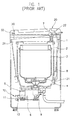
- FIG. 1 A cross-sectional view of a conventional washing machine of the type described above is illustrated in Figure 1 and includes a laundry weight sensor 10; a water sensor 20 for determining when a particular volume of water has been supplied to the tub 2 corresponding to the sensed laundry weight; and an imbalance sensor 30 for sensing dynamic imbalance of the drum 3 during rotation.
- the laundry weight sensor 10 includes a permanent magnet 11 fixedly mounted to a pulley 6 of a washing motor 5, and a coil 12 for generating a variable electrical signal as it passes the permanent magnet 11.
- the sensor 10 senses the weight of the laundry by determining the number of rotations or the motor pulley 6 that occur due to inertia once the power supply to the motor has been terminated. The number of rotations is dependent upon the weight of the laundry in the drum 3.
- the laundry weight is obtained by determining the number of signal pulses generated by the coil 12 which is magnetized by the permanent magnet 12 during inertial rotation of the drum. Once the laundry weight is determined, the control unit sets an appropriate water volume accordingly.
- the water sensor 20 includes an air trap 21 provided in a lower portion of the water tub 2, within which air is compressed depending upon the amount of water in the tub 2, and a mechanical pressure sensing member 22 for generating variable frequencies ranging from 22kHz to 26kHz according to the pressure of air in the air trap 21. As the level of water in the tub 2 rises the air in the air trap 21 is compressed and exerts a pressure against the mechanical pressure sensing member 22, which thereby generates variable frequencies of the range of 26kHz-22kHz.
- the generated frequency is input to the control unit which ascertains the present volume of water in the tub 2.
- the control unit which ascertains the present volume of water in the tub 2.
- the imbalance sensor 30 includes a lever 31 remote from an upper end of the water tub 2 for sensing an abnormal motion of the water tub 2 due to imbalanced rotation of the washing drum 3; and a switch 32 which is connected to one end of the lever 31 which generates a signal depending on movement of the lever 31 or the opening of the door.
- a conventional washing machine also includes a housing 1, an agitator 4 and tub suspension bars 8.
- a disadvantage with a conventional washing machine of the type described above is the provision of a laundry weight sensor, a water level sensor and an imbalance sensor, substantially increases the production cost of the washing machine and makes it significantly more complicated and time consuming to manufacture.
- the laundry weight sensor senses the laundry weight by utilizing inertial force, it is difficult to accurately measure the weight of the laundry when it is unevenly distributed in the drum. Inaccurate measurement of the laundry weight prevents an optimum amount of water for washing from being supplied to the drum, thereby lowering the efficiency of the washing machine.
- Washing machines having means for determining the weight of the laundry, the amount of water supplied to the washing drum and imbalanced rotatation during a spin cycle are also known from DE-A-4141213.
- This document discloses a washing machine including sensing means for determining the position of the drum and the height of the water level introduced therein. The measured valves are fed to a computer which determines parameters such as mass of dry laundry, type of laundry, water level and water quantity absorbed by the laundry.
- the sensing means includes a ferromagnetic core displaceable within a coil, the position of the core depending on the amount of laundry and/or water in the drum.
- DE-A-3838998 discloses a washing machine including a load indicator employing an electric coil surrounding a spring and a magnetic core attached to the tub. Movement of the tub and core is detected as a change in magnetic flux which is used to determine the change in weight of the drum.
- a washing machine is characterised in that the sensing means further comprises a Hall element fixed relative to the magnet and spaced therefrom to generate a voltage signal corresponding to the magnetic field generated by the magnet whereby displacement of the magnet towards or away from the Hall element causes the magnetic field to change and alter the voltage signal generated by the Hall element, the Hall element including signal amplifying means to amplify the voltage signal generated by the Hall element and signal converting means for converting the voltage signal into a value which is proportional to the distance between the Hall element and the magnet.
- the sensing means is operable to detect displacement of the tub caused by vibration due to uneven distribution of laundry in the drum during rotation.
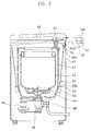
- the washing machine includes a housing 41; a door 49 provided in the upper surface of the housing 41; a water tub 42 provided in the housing 41; a drum 43 rotatably mounted in the tub 42; an agitator 44 mounted in the drum 43 and rotatable in a forward or backward direction to generate water currents; a motor 45 provided below the tub 42 which drives the agitator 44 via power transmission apparatus 46 at low speed during the wash cycle or both the washing drum 43 and the agitator 44 at a high speed during the spin drying cycle.
- the washing machine further includes a water supply valve 47 connected to a water supply, a drain valve 48 for draining water from the tub 42, at least one suspension bar 50 having an upper end 50a coupled to the housing 41 and a lower end 50b coupled to the tub 42 to support the tub 42; and a hybrid sensor 100 which is mounted to an upper end 50a of the suspension bar 50 and which is capable of generating signals indicative of the weight of the laundry and water fed to the tub 42, and dynamic imbalance of the washing tub 43 determined by measurement of the displacement of the suspension bar 50 caused by uneven distribution of the laundry and subsequent variation in load applied to the tub 42 during rotation of the drum 43.
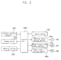
- the washing machine further includes a function selection portion 201 to enable a user to input various control parameters, a display panel 2C2 for displaying the selected functions input via the function selection portion 203 to generate a warning signal when an abnormal operating condition is detected; a control unit 200 which receives an output signal from the hybrid sensor 100 and determines the weight of the laundry, water feed weight and dynamic imbalance of the tub 42 on the basis of the output signal of the hybrid sensor 100 and generates control signals, a motor driving portion 45a to control the motor 45 to generate water currents and perform the spin drying cycle according to the signal output from the control unit 200; a water supply valve driving portion 48a to control the drain valve 48 to drain water from the tub 42 in accordance with a signal output from the control unit 200.
- a function selection portion 201 to enable a user to input various control parameters
- a display panel 2C2 for displaying the selected functions input via the function selection portion 203 to generate a warning signal when an abnormal operating condition is detected
- a control unit 200 which receives an output signal from the hybrid sensor 100
- the upper end 50a of the suspension bar 50 passes through a first fixing member 51 on the inner wall of the housing 44 the lower end 50b passes through a second fixing member 52 on the outside of the tub 42.
- the lower end 50b of the suspension bar 50 is provided with a damper 53 to absorb vibrations of the tub 42.
- the load exerted on the suspension bar 50 varies depending on the weight of the laundry and water in the tub 42, and vibration of the tub 42 generated during the spin drying cycle.
- the load is transmitted to the hybrid sensor 100 mounted on the upper end 50a of suspension bar 50 which senses the laundry weight, and dynamic imbalance in dependence on the load variation.
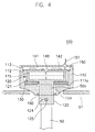
- the hybrid sensor 100 includes a housing 100; a permanent magnet 115 disposed within housing 110 movable in a vertical direction together with the suspension bar 50 according to the variation in load applied to the tub 42; an elastic member 130 disposed between the base 111a of the housing 110 and the permanent magnet 115 which is compressed in proportion to the load applied to the tub 42 and a hall element 140 which is mounted spaced from and facing the upper surface of the permanent magnet 115 for generating voltage signals corresponding to the variation in magnetic force caused by movement of the permanent magnet 115.
- the hybrid sensor 100 further includes a signal amplifier 144 to amplify the voltage signals generated by the hall element 140 to enable the signal to be processed; a signal converting portion 141 which receives the amplified voltage signal from the signal amplifier 144 and converts it from a voltage which is inversely proportional to the distance between the permanent magnet 115 and the hall element 140, to a voltage which is proportional to the distance between the permanent magnet 115 and hall element: 140, a printed circuit board 142 attached to the inside of housing 110 on which the hall element 140, the signal amplifier 144 and the signal converting portion 141 is mounted, a cover 150 disposed on the top of the housing 110, and an output line 151 for transmitting signals processed in the signal converting portion 141 to the control unit 200.
- a signal amplifier 144 to amplify the voltage signals generated by the hall element 140 to enable the signal to be processed
- a signal converting portion 141 which receives the amplified voltage signal from the signal amplifier 144 and converts it from a voltage which is inversely proportion
- the inside of the housing 110 is provided with a first shoulder 112 on which is seated the printed circuit board 142, and a second shoulder 113 on which is seated the cover 150.
- the first shoulder 112 is located so as to position the hall element 150 at a predetermined distance from the permanent magnet 115, when the magnet 115 is closest in its range of movement.
- the second shoulder 113 is also spaced from the first shoulder 112 by a predetermined distance to enable the signal converting portion 141 to be mounted on the printed circuit board 142.
- the permanent magnet 115 is disposed in a member 120 attached to the upper enc 50a of the suspension bar 50 that includes a cup shaped portion 121 for receiving the permanent magnet 115; and a hollow coupling portion 122 extending outside the housing 110 from the cup shaped portion 121 which receives the upper end 50a of the suspension bar 50.
- a coupling hole 124 is provided in an upper end 50a of the suspension bar 50 and a lower portion of the coupling portion 122, respectively, and a fixing pin 125 is inserted into the coupling holes 124, to connect the coupling portion 122 to the upper end of the suspension bar 50.
- the coupling portion 122 passes through an opening 114 in the housing 110 and a sealing member 160 is disposed between them.
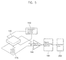
- a constant current I is applied to the hall element 140 from a source 143 and the Hall element 140 is subjected to a magnetic field H at right angles with the source I.
- the hall element 140 generates linear voltage signals that correspond to the magnetic force of the magnetic field H. If the permanent magnet 115 is disposed close to the hall element 140, the magnetic field H becomes intensified, thereby increasing the voltage signal generated by the hall element 140. However, as the permanent magnet 15 moves further away from the hall element: 140, the magnetic field H weakens, thereby reducing the voltage signal generated by the hall element 140.
- the hall element 140 generates a higher voltage signal.
- a larger distance between the permanent magnet 115 and the hall element 140 means that the load applied to the suspension bar 50 has increased. Accordingly, the hall element 140 generates a lower voltage signal.
- the control unit 200 receives voltage signals from the sensor 100 and determines the weight of the laundry when dry. It also determines the volume of water as it is fed to the drum 24 whilst the water supply is open and the total volume of water when the supply is closed.
- the spin drying cycle comprises a number of intermittent steps and the hybrid sensor 100 supplies an output voltage signal to an analog-to-digital (A/D) conversion terminal of the control unit 200, during each intermittent step which converts it into a digital value from which the control unit 200 determines any imbalance in the tub 42 caused by uneven distribution of laundry within the drum.
- A/D analog-to-digital
- the output voltage characteristic of the hybrid sensor 100 varies intermittently during the spin drying cycle and can be expressed numerically as an imbalance weight in accordance with experimental data. For example, if the output voltage of the hybrid sensor is measured when the load is applied to the suspension bar 50 is 0.1kg, an imbalance weight can be calculated by intermittently applying the measured output voltage to the output voltage of the hybrid sensor 100 during the spin drying cycle.
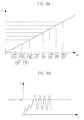
- the signal converting portion 141 When imbalance is present, the signal converting portion 141 generates the voltage signal shown in Figure 6B during the spin drying cycle. More specifically, if an imbalanced rotation of the washing drum 43 occurs due to the uneven distribution of laundry within the drum 43, the tub 42 vibrates and the suspension bar 50 moves up and down thus changing the position of the permanent magnet 115 in the hybrid sensor 100 in relation to the hall element 140. This causes the hall element 140 to generate a pulse-type voltage signal as shown in Figure 6B.
- This pulse-type voltage signal is fed to the control unit 200 through the signal converting portion 141, and if it is greater than a predetermined reference voltage, imbalance can be determined by applying the hybrid sensor 100 output voltage per a reference load to this voltage signal higher than the predetermined reference voltage.
- the control unit 200 checks an initial output voltage Vout of the hybrid sensor 100 before laundry is placed in the washing drum 43 (S102).
- the load applied to the suspension bar 50 increases to an extent equal to the laundry weight, thus increasing the output voltage of the hybrid sensor 100.
- the control unit 200 determines the laundry weight by calculating the voltage difference between the two voltages (S104).
- the control unit determines an optimum water volume in dependence on the sensed laundry weight (S105) and generates a control signal to control the water supply valve driving portion 47a to cause water to be supplied to the tub 42.
- a water supply time is also determined by initiating a counter when the supply valve 47 opens (S106).
- the volume of water supplied to the tub 42 increases the load on the suspension bar 50, thereby further increasing the output voltage Vout.
- the control unit 200 continuously reads the output voltage Vout as it increases whilst water is supplied to the tub 42 and compares it with the initial output voltage (S102) thereby determining the volume of water in the tub 42 (S107).
- the control unit 200 determines (S108) when the volume of the water sensed in step (S107) reaches a predetermined reference volume of 10 litres and the time taken. From the measured time, the time for the optimum volume of water determined in step (S105) to be supplied to the tub 42 can be calculated (S109).
- step (S110) determines whether the present water volume has reached the optimum feed water volume determined in accordance with sensed laundry weight in step (S105). If it has been reached, the control unit 200 generates a control signal which is fed to the water supply valve driving portion 47a to close the water supply valve 47, and any further supply to the tub (S112).
- step (S111) determines whether the water supply time is over the optimum water supply time determined in step (S109). If it is, a control signal is fed to the water supply valve driving portion 47a to close the water supply valve 47, and terminate the water supply operation (S112). Step (S111) is provided to ensure that too much water is prevented from being supplied to tub 42.
- the washing machine When the water has been supplied to the tub 42, the washing machine performs a washing cycle followed by a draining cycle.
- FIG. 8 A flowchart illustrating a control method of the washing machine in the draining step is shown in. Figure 8.
- the control unit calculates a draining cycle finishing time in dependence on the optimum water supply time ascertained in step (S109) of Figure 7 (S202).
- the draining cycle finishing time is shorter than the water supply finishing time, because some of the water is retained by the laundry and cannot be drained therefrom.
- a control signal is fed to a drain valve driving portion 48a to open the drain valve 48.
- the duration of the draining time is measured from the time that the drain valve opens (S203).
- the load exerted on the suspension bar 50 is reduced and is restored to its original location as a result of the restoring force provided by the elastic member 130.
- the permanent magnet 15 mounted in the member 120 moves together with the suspension bar reducing the distance between the hall element 140 and the permanent magnet 115.
- the output voltage of the hybrid sensor 100 reduces as the water is drained from the tub 42.
- the control unit 200 continuously determines the output voltage of the hybrid sensor 100 and compares it with the voltage stored before the draining cycle has begun, thereby determining the water drain volume (S204) during the draining cycle.
- step (S205) the control unit determines whether the drain volume has reached a predetermined reference value (i.e. a drain completion value) which is determined in dependence on the type of laundry which retains some of the water.
- a predetermined reference value i.e. a drain completion value
- the control unit 200 determines whether the draining time exceeds the draining cycle finishing time determined in step (S202) (S207). If it does, the control unit 200 generates a warning signal through the warning portion 202 (S208), and stops the draining cycle (S206).
- a rinsing cycle is performed, followed by a spin drying cycle.
- the spin drying cycle comprises three or four intermittent drying steps and a main drying step.
- the control unit 200 determines the imbalance weight upon receipt of an output signal from the hall element 140 via a signal converting portion 141.
- the intermittent spin drying steps prevent damage to the motor 45 caused by an overload and assists in preventing uneven distribution of laundry in the drum 43. However, some imbalance still occurs which cannot be prevented by the intermittent spin drying steps.
- the control unit 200 determines the weight x of the water tub 42 using the hybrid sensor 100 (S302) and spin drying time Tb is calculated in dependence on sensed weight x (S303).
- Equation K (x - A1)/A1 is used, in which K represents the load applied to the water tub 42, and A1 indicates the laundry weight.
- the laundry weight A1 is that determined in step (S104) and the weight x of the tub 42 includes the weight of the laundry which has retained some water. Accordingly, the variable K represents how much water is retained by the laundry. If the variable K has a high value, the spin drying cycle Tb is set to a long time whereas if the variable K is a low value, the spin drying time Tb is set to a shorter time.
- the control unit 200 outputs a control signal to drive the motor 45 during a predetermined time (S304) in a first acceleration step.
- a first output voltage P1 of the hybrid sensor 100 is subsequently sensed for a period of 5 seconds (S305).
- S305 a second acceleration step is performed (S306) and a second output voltage P2 of the hybrid sensor 100 is sensed (S307).
- S308 A third acceleration step is performed (S308), and a third output voltage P3 is subsequently sensed (S309) during 5 seconds after the third acceleration step.
- the control unit 200 reads the output voltages P1-P3 via it's A/D conversion terminal and converts each of them into digital signals, and compares the digital signal with a predetermined reference voltage to determine an imbalance. If the digital signal is over the predetermined reference voltage, each of the output voltages Pa-P3 is converted into the imbalance weight (S310) by using the hybrid sensor 100's output voltage and a predetermined reference load (e.g. 0.1kg).
- a predetermined reference load e.g. 0.1kg
- the control unit 200 compares (S313) the average imbalance weight G with a predetermined reference imbalance weight (e.g. 0.8kg) to determine whether the imbalance is excessive, in which case the spin drying cycle is stopped.
- a predetermined reference imbalance weight e.g. 0.8kg
- the control unit 200 If the average imbalance weight G is over the reference imbalance weight 0.8kg in the step (S313), the control unit 200 outputs a control signal to the washing motor driving portion 45a, to stop the washing motor 45 (S314), and then performs an imbalance reducing step (S315) to reduce the imbalance.
- This imbalance reducing step (S315) comprises a rinsing cycle to more evenly distribute the laundry within the drum 43 and a further draining cycle before starting the spin drying cycle again.
- control unit 200 determines an imbalance state capable of continuously performing the spin drying cycle, and continuously performs the spin drying cycle by accelerating the washing motor 45 (S316).
- the control unit 200 determines (S317) whether the spin drying has reached the predetermined spin drying time Tb of step (S303). If the present spin drying time has reached the predetermined dehydration time Tb in step (S317), the control unit 200 outputs a control signal to the motor driving portion 45a and, stops both the motor 45 and the spin drying cycle (S318).
- the washing machine having the hybrid sensor senses the laundry weight, the feed water weight, and the imbalance weight using only one hybrid sensor has a simple structure, and easily performs signal processing.
Landscapes
- Engineering & Computer Science (AREA)
- Textile Engineering (AREA)
- Control Of Washing Machine And Dryer (AREA)
- Main Body Construction Of Washing Machines And Laundry Dryers (AREA)
- Detail Structures Of Washing Machines And Dryers (AREA)
Description
- The present invention relates to a washing machine including a tub, a drum rotatably mounted in the tub for receiving laundry to be washed, sensing means including a magnet for generating signals indicative of the amount of laundry and water in the tub by detecting displacement of the tub when laundry is placed in the drum and water is supplied thereto, and control means for controlling the operation of the washing machine in dependence on said signals. Such a washing machine is known from EP-A-0396058.
- In a conventional washing machine an agitator is rotated by a motor to generate water currents and wash laundry placed within it. Washing, rinsing, draining and spin drying cycles are pre-programmed into a microcomputer which controls operation of the washing machine. When a particular program is selected by the user, the laundry is washed according to that program.
- In one type of conventional drum type washing machine, the weight of the laundry placed in the drum is sensed and an appropriate amount of water is selected corresponding to the sensed laundry weight. To achieve a fully automatic washing process, a sensor is required for detecting the weight of the laundry and also to detect the volume of water supplied to the tub. A third sensor is generally provided to detect any imbalance in the drum during rotation due to uneven distribution of laundry.
- A cross-sectional view of a conventional washing machine of the type described above is illustrated in Figure 1 and includes a
laundry weight sensor 10; awater sensor 20 for determining when a particular volume of water has been supplied to thetub 2 corresponding to the sensed laundry weight; and animbalance sensor 30 for sensing dynamic imbalance of thedrum 3 during rotation. - The
laundry weight sensor 10 includes apermanent magnet 11 fixedly mounted to apulley 6 of awashing motor 5, and acoil 12 for generating a variable electrical signal as it passes thepermanent magnet 11. Thesensor 10 senses the weight of the laundry by determining the number of rotations or themotor pulley 6 that occur due to inertia once the power supply to the motor has been terminated. The number of rotations is dependent upon the weight of the laundry in thedrum 3. - The laundry weight is obtained by determining the number of signal pulses generated by the
coil 12 which is magnetized by thepermanent magnet 12 during inertial rotation of the drum. Once the laundry weight is determined, the control unit sets an appropriate water volume accordingly. - The
water sensor 20 includes anair trap 21 provided in a lower portion of thewater tub 2, within which air is compressed depending upon the amount of water in thetub 2, and a mechanicalpressure sensing member 22 for generating variable frequencies ranging from 22kHz to 26kHz according to the pressure of air in theair trap 21. As the level of water in thetub 2 rises the air in theair trap 21 is compressed and exerts a pressure against the mechanicalpressure sensing member 22, which thereby generates variable frequencies of the range of 26kHz-22kHz. - The generated frequency is input to the control unit which ascertains the present volume of water in the
tub 2. When the volume of water reaches a predetermined level corresponding to the laundry weight sensed by thesensor 10, the water supply is stopped, and the washing, rinsing and spin drying steps are sequentially performed. - The
imbalance sensor 30 includes alever 31 remote from an upper end of thewater tub 2 for sensing an abnormal motion of thewater tub 2 due to imbalanced rotation of thewashing drum 3; and aswitch 32 which is connected to one end of thelever 31 which generates a signal depending on movement of thelever 31 or the opening of the door. - If the
water tub 2 vibrates due to imbalanced rotation of thedrum 3, thelever 31 is operated and theswitch 32 generates a signal which is input to the control unit. - A conventional washing machine also includes a
housing 1, anagitator 4 andtub suspension bars 8. - A disadvantage with a conventional washing machine of the type described above is the provision of a laundry weight sensor, a water level sensor and an imbalance sensor, substantially increases the production cost of the washing machine and makes it significantly more complicated and time consuming to manufacture.
- Furthermore as the laundry weight sensor senses the laundry weight by utilizing inertial force, it is difficult to accurately measure the weight of the laundry when it is unevenly distributed in the drum. Inaccurate measurement of the laundry weight prevents an optimum amount of water for washing from being supplied to the drum, thereby lowering the efficiency of the washing machine.
- Washing machines having means for determining the weight of the laundry, the amount of water supplied to the washing drum and imbalanced rotatation during a spin cycle are also known from DE-A-4141213. This document discloses a washing machine including sensing means for determining the position of the drum and the height of the water level introduced therein. The measured valves are fed to a computer which determines parameters such as mass of dry laundry, type of laundry, water level and water quantity absorbed by the laundry. The sensing means includes a ferromagnetic core displaceable within a coil, the position of the core depending on the amount of laundry and/or water in the drum. DE-A-3838998 discloses a washing machine including a load indicator employing an electric coil surrounding a spring and a magnetic core attached to the tub. Movement of the tub and core is detected as a change in magnetic flux which is used to determine the change in weight of the drum.
- A washing machine according to the present invention is characterised in that the sensing means further comprises a Hall element fixed relative to the magnet and spaced therefrom to generate a voltage signal corresponding to the magnetic field generated by the magnet whereby displacement of the magnet towards or away from the Hall element causes the magnetic field to change and alter the voltage signal generated by the Hall element, the Hall element including signal amplifying means to amplify the voltage signal generated by the Hall element and signal converting means for converting the voltage signal into a value which is proportional to the distance between the Hall element and the magnet.
- Preferably, the sensing means is operable to detect displacement of the tub caused by vibration due to uneven distribution of laundry in the drum during rotation.
- An embodiment of the present invention will now be described, by way of example only, with reference to Figures 2 to 9 of the accompanying drawings, in which:-
- FIGURE 1 is a cross-sectional view of a prior art washing machine having all of a laundry weight sensor, a water level sensor and an imbalance sensor;
- FIGURE 2 is a cross-sectional view of a washing machine having the hybrid sensor according to an embodiment of the invention;
- FIGURE 3 is a block diagram of a washing machine having the hybrid sensor according to an embodiment of the invention;
- FIGURE 4 is a cross-sectional view of the hybrid sensor according to an embodiment of the invention;
- FIGURE 5 is a circuit diagram showing a basic principle of the hybrid sensor according to an embodiment of the invention;
- FIGURE 6A-6B show output characteristics of a hybrid sensor according to an embodiment of the invention;
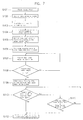
- FIGURE 7 is a flowchart illustrating a control method of a washing machine having the hybrid sensor according to an embodiment of the invention, which is applied to a water supply step from a power supply step;
- FIGURE 8 is a flowchart illustrating a control method of the washing machine according to an embodiment of the invention, which is applied to a draining cycle; and
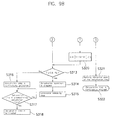
- FIGURES 9A-9B are flowcharts illustrating a control method of the washing machine according to an embodiment of the invention, which is applied to a spin drying cycle.
-
- As shown in Figure 2, the washing machine includes a
housing 41; adoor 49 provided in the upper surface of thehousing 41; awater tub 42 provided in thehousing 41; adrum 43 rotatably mounted in thetub 42; anagitator 44 mounted in thedrum 43 and rotatable in a forward or backward direction to generate water currents; amotor 45 provided below thetub 42 which drives theagitator 44 viapower transmission apparatus 46 at low speed during the wash cycle or both thewashing drum 43 and theagitator 44 at a high speed during the spin drying cycle. - The washing machine further includes a
water supply valve 47 connected to a water supply, adrain valve 48 for draining water from thetub 42, at least onesuspension bar 50 having anupper end 50a coupled to thehousing 41 and alower end 50b coupled to thetub 42 to support thetub 42; and ahybrid sensor 100 which is mounted to anupper end 50a of thesuspension bar 50 and which is capable of generating signals indicative of the weight of the laundry and water fed to thetub 42, and dynamic imbalance of thewashing tub 43 determined by measurement of the displacement of thesuspension bar 50 caused by uneven distribution of the laundry and subsequent variation in load applied to thetub 42 during rotation of thedrum 43. - As shown in Figure 3, the washing machine further includes a
function selection portion 201 to enable a user to input various control parameters, a display panel 2C2 for displaying the selected functions input via thefunction selection portion 203 to generate a warning signal when an abnormal operating condition is detected; acontrol unit 200 which receives an output signal from thehybrid sensor 100 and determines the weight of the laundry, water feed weight and dynamic imbalance of thetub 42 on the basis of the output signal of thehybrid sensor 100 and generates control signals, amotor driving portion 45a to control themotor 45 to generate water currents and perform the spin drying cycle according to the signal output from thecontrol unit 200; a water supplyvalve driving portion 48a to control thedrain valve 48 to drain water from thetub 42 in accordance with a signal output from thecontrol unit 200. - To support the
washing tub 42, theupper end 50a of thesuspension bar 50 passes through afirst fixing member 51 on the inner wall of thehousing 44 thelower end 50b passes through asecond fixing member 52 on the outside of thetub 42. Thelower end 50b of thesuspension bar 50 is provided with adamper 53 to absorb vibrations of thetub 42. - The load exerted on the
suspension bar 50 varies depending on the weight of the laundry and water in thetub 42, and vibration of thetub 42 generated during the spin drying cycle. The load is transmitted to thehybrid sensor 100 mounted on theupper end 50a ofsuspension bar 50 which senses the laundry weight, and dynamic imbalance in dependence on the load variation. - A cross-sectional view of the
hybrid sensor 100 is illustrated in Figure 4 and a circuit diagram showing the basic principle of thehybrid sensor 100 is illustrated in Figure 5. Thehybrid sensor 100 includes ahousing 100; apermanent magnet 115 disposed withinhousing 110 movable in a vertical direction together with thesuspension bar 50 according to the variation in load applied to thetub 42; anelastic member 130 disposed between thebase 111a of thehousing 110 and thepermanent magnet 115 which is compressed in proportion to the load applied to thetub 42 and ahall element 140 which is mounted spaced from and facing the upper surface of thepermanent magnet 115 for generating voltage signals corresponding to the variation in magnetic force caused by movement of thepermanent magnet 115. - The
hybrid sensor 100 further includes asignal amplifier 144 to amplify the voltage signals generated by thehall element 140 to enable the signal to be processed; asignal converting portion 141 which receives the amplified voltage signal from thesignal amplifier 144 and converts it from a voltage which is inversely proportional to the distance between thepermanent magnet 115 and thehall element 140, to a voltage which is proportional to the distance between thepermanent magnet 115 and hall element: 140, a printedcircuit board 142 attached to the inside ofhousing 110 on which thehall element 140, thesignal amplifier 144 and thesignal converting portion 141 is mounted, acover 150 disposed on the top of thehousing 110, and anoutput line 151 for transmitting signals processed in thesignal converting portion 141 to thecontrol unit 200. - The inside of the
housing 110 is provided with afirst shoulder 112 on which is seated the printedcircuit board 142, and asecond shoulder 113 on which is seated thecover 150. Thefirst shoulder 112 is located so as to position thehall element 150 at a predetermined distance from thepermanent magnet 115, when themagnet 115 is closest in its range of movement. Thesecond shoulder 113 is also spaced from thefirst shoulder 112 by a predetermined distance to enable thesignal converting portion 141 to be mounted on the printedcircuit board 142. - The
permanent magnet 115 is disposed in amember 120 attached to theupper enc 50a of thesuspension bar 50 that includes a cup shapedportion 121 for receiving thepermanent magnet 115; and ahollow coupling portion 122 extending outside thehousing 110 from the cup shapedportion 121 which receives theupper end 50a of thesuspension bar 50. Acoupling hole 124 is provided in anupper end 50a of thesuspension bar 50 and a lower portion of thecoupling portion 122, respectively, and afixing pin 125 is inserted into thecoupling holes 124, to connect thecoupling portion 122 to the upper end of thesuspension bar 50. Thecoupling portion 122 passes through an opening 114 in thehousing 110 and a sealingmember 160 is disposed between them. - Referring now to Figure 5, a constant current I is applied to the
hall element 140 from asource 143 and theHall element 140 is subjected to a magnetic field H at right angles with the source I. As a result, thehall element 140 generates linear voltage signals that correspond to the magnetic force of the magnetic field H. If thepermanent magnet 115 is disposed close to thehall element 140, the magnetic field H becomes intensified, thereby increasing the voltage signal generated by thehall element 140. However, as the permanent magnet 15 moves further away from the hall element: 140, the magnetic field H weakens, thereby reducing the voltage signal generated by thehall element 140. - The smaller the distance between the
permanent magnet 115 and thehall element 140, the lower the load applied to thesuspension bar 50. Accordingly, as the load applied to thesuspension bar 50 reduces, thehall element 140 generates a higher voltage signal. On the contrary, a larger distance between thepermanent magnet 115 and thehall element 140 means that the load applied to thesuspension bar 50 has increased. Accordingly, thehall element 140 generates a lower voltage signal. - When the output signal from the
hall element 140 is inverse-transformed by thesignal converting portion 141, an output voltage as shown in Figure 6A is generated from which it is clear that the output voltage signal of thehybrid sensor 100 varies in proportion to the load applied to thesuspension bar 50. - The
control unit 200 receives voltage signals from thesensor 100 and determines the weight of the laundry when dry. It also determines the volume of water as it is fed to the drum 24 whilst the water supply is open and the total volume of water when the supply is closed. - The spin drying cycle comprises a number of intermittent steps and the
hybrid sensor 100 supplies an output voltage signal to an analog-to-digital (A/D) conversion terminal of thecontrol unit 200, during each intermittent step which converts it into a digital value from which thecontrol unit 200 determines any imbalance in thetub 42 caused by uneven distribution of laundry within the drum. - When the tub is imbalanced the output voltage characteristic of the
hybrid sensor 100 varies intermittently during the spin drying cycle and can be expressed numerically as an imbalance weight in accordance with experimental data. For example, if the output voltage of the hybrid sensor is measured when the load is applied to thesuspension bar 50 is 0.1kg, an imbalance weight can be calculated by intermittently applying the measured output voltage to the output voltage of thehybrid sensor 100 during the spin drying cycle. - When imbalance is present, the
signal converting portion 141 generates the voltage signal shown in Figure 6B during the spin drying cycle. More specifically, if an imbalanced rotation of thewashing drum 43 occurs due to the uneven distribution of laundry within thedrum 43, thetub 42 vibrates and thesuspension bar 50 moves up and down thus changing the position of thepermanent magnet 115 in thehybrid sensor 100 in relation to thehall element 140. This causes thehall element 140 to generate a pulse-type voltage signal as shown in Figure 6B. - This pulse-type voltage signal is fed to the
control unit 200 through thesignal converting portion 141, and if it is greater than a predetermined reference voltage, imbalance can be determined by applying thehybrid sensor 100 output voltage per a reference load to this voltage signal higher than the predetermined reference voltage. - A method of controlling a washing machine incorporating the
hybrid sensor 100 will now be described with reference to Figures 7-9. - Referring to Figure 7, when power is supplied to the washing machine (S101), the
control unit 200 checks an initial output voltage Vout of thehybrid sensor 100 before laundry is placed in the washing drum 43 (S102). When laundry is placed in the drum 43 (S103), the load applied to thesuspension bar 50 increases to an extent equal to the laundry weight, thus increasing the output voltage of thehybrid sensor 100. Thecontrol unit 200 determines the laundry weight by calculating the voltage difference between the two voltages (S104). - The control unit determines an optimum water volume in dependence on the sensed laundry weight (S105) and generates a control signal to control the water supply
valve driving portion 47a to cause water to be supplied to thetub 42. A water supply time is also determined by initiating a counter when thesupply valve 47 opens (S106). - The volume of water supplied to the
tub 42 increases the load on thesuspension bar 50, thereby further increasing the output voltage Vout. Thecontrol unit 200 continuously reads the output voltage Vout as it increases whilst water is supplied to thetub 42 and compares it with the initial output voltage (S102) thereby determining the volume of water in the tub 42 (S107). - The
control unit 200 determines (S108) when the volume of the water sensed in step (S107) reaches a predetermined reference volume of 10 litres and the time taken. From the measured time, the time for the optimum volume of water determined in step (S105) to be supplied to thetub 42 can be calculated (S109). - When the optimum water supply has been calculated in step (S109), step (S110) determines whether the present water volume has reached the optimum feed water volume determined in accordance with sensed laundry weight in step (S105). If it has been reached, the
control unit 200 generates a control signal which is fed to the water supplyvalve driving portion 47a to close thewater supply valve 47, and any further supply to the tub (S112). - However, if the present water volume has not reached the optimum feed volume in step (S110), step (S111) determines whether the water supply time is over the optimum water supply time determined in step (S109). If it is, a control signal is fed to the water supply
valve driving portion 47a to close thewater supply valve 47, and terminate the water supply operation (S112). Step (S111) is provided to ensure that too much water is prevented from being supplied totub 42. - When the water has been supplied to the
tub 42, the washing machine performs a washing cycle followed by a draining cycle. - A flowchart illustrating a control method of the washing machine in the draining step is shown in. Figure 8. When the draining cycle begins (S201), the control unit calculates a draining cycle finishing time in dependence on the optimum water supply time ascertained in step (S109) of Figure 7 (S202). The draining cycle finishing time is shorter than the water supply finishing time, because some of the water is retained by the laundry and cannot be drained therefrom.
- When the cycle is initiated, a control signal is fed to a drain
valve driving portion 48a to open thedrain valve 48. The duration of the draining time is measured from the time that the drain valve opens (S203). When the water in the tub has been drained, the load exerted on thesuspension bar 50 is reduced and is restored to its original location as a result of the restoring force provided by theelastic member 130. The permanent magnet 15 mounted in themember 120 moves together with the suspension bar reducing the distance between thehall element 140 and thepermanent magnet 115. As a result, the output voltage of thehybrid sensor 100 reduces as the water is drained from thetub 42. Thecontrol unit 200 continuously determines the output voltage of thehybrid sensor 100 and compares it with the voltage stored before the draining cycle has begun, thereby determining the water drain volume (S204) during the draining cycle. - In step (S205) the control unit determines whether the drain volume has reached a predetermined reference value (i.e. a drain completion value) which is determined in dependence on the type of laundry which retains some of the water.
- If the drain volume reaches the drain completion value in step (S205), the
control unit 200 determines whether the draining time exceeds the draining cycle finishing time determined in step (S202) (S207). If it does, thecontrol unit 200 generates a warning signal through the warning portion 202 (S208), and stops the draining cycle (S206). - After performing the draining cycle, a rinsing cycle is performed, followed by a spin drying cycle.
- A method of sensing imbalance by using the
hybrid sensor 100 will now be described with reference to Figures 9A-9B. The spin drying cycle comprises three or four intermittent drying steps and a main drying step. During each step, thecontrol unit 200 determines the imbalance weight upon receipt of an output signal from thehall element 140 via asignal converting portion 141. The intermittent spin drying steps prevent damage to themotor 45 caused by an overload and assists in preventing uneven distribution of laundry in thedrum 43. However, some imbalance still occurs which cannot be prevented by the intermittent spin drying steps. - As shown in Figures 9A-9B, when the spin drying cycle starts (S301), the
control unit 200 determines the weight x of thewater tub 42 using the hybrid sensor 100 (S302) and spin drying time Tb is calculated in dependence on sensed weight x (S303). - To calculate the dehydration time Tb, the equation K = (x - A1)/A1 is used, in which K represents the load applied to the
water tub 42, and A1 indicates the laundry weight. - The laundry weight A1 is that determined in step (S104) and the weight x of the
tub 42 includes the weight of the laundry which has retained some water. Accordingly, the variable K represents how much water is retained by the laundry. If the variable K has a high value, the spin drying cycle Tb is set to a long time whereas if the variable K is a low value, the spin drying time Tb is set to a shorter time. - The
control unit 200 outputs a control signal to drive themotor 45 during a predetermined time (S304) in a first acceleration step. A first output voltage P1 of thehybrid sensor 100 is subsequently sensed for a period of 5 seconds (S305). When the first output voltage P1 has been sensed in step (S305), a second acceleration step is performed (S306) and a second output voltage P2 of thehybrid sensor 100 is sensed (S307). A third acceleration step is performed (S308), and a third output voltage P3 is subsequently sensed (S309) during 5 seconds after the third acceleration step. - When the first to third output voltages (P1, P2 and P3) are obtained, the
control unit 200 reads the output voltages P1-P3 via it's A/D conversion terminal and converts each of them into digital signals, and compares the digital signal with a predetermined reference voltage to determine an imbalance. If the digital signal is over the predetermined reference voltage, each of the output voltages Pa-P3 is converted into the imbalance weight (S310) by using thehybrid sensor 100's output voltage and a predetermined reference load (e.g. 0.1kg). Herein, the first output voltage P1 is converted to the first imbalance weight g1, the second output voltage P2 is converted to the second imbalance weight g2, and the third output voltage P3 is converted to the third imbalance weight g3. - The
control unit 200 uses an equation g1=g2±5% to determine whether the first imbalance weight g1 and the second imbalance weight g2 are within an error (S311). - If the equation g1=g2±5% is satisfied in step (S311), the
control unit 200 calculates (S312) an average imbalance weight G by using an equation G=(g1+g2)/2. - When the average imbalance weight G is calculated in the step (S312), the
control unit 200 compares (S313) the average imbalance weight G with a predetermined reference imbalance weight (e.g. 0.8kg) to determine whether the imbalance is excessive, in which case the spin drying cycle is stopped. - If the average imbalance weight G is over the reference imbalance weight 0.8kg in the step (S313), the
control unit 200 outputs a control signal to the washingmotor driving portion 45a, to stop the washing motor 45 (S314), and then performs an imbalance reducing step (S315) to reduce the imbalance. This imbalance reducing step (S315) comprises a rinsing cycle to more evenly distribute the laundry within thedrum 43 and a further draining cycle before starting the spin drying cycle again. - If the average imbalance weight G is below the reference imbalance weight 0.8kg in step (S313), the
control unit 200 determines an imbalance state capable of continuously performing the spin drying cycle, and continuously performs the spin drying cycle by accelerating the washing motor 45 (S316). - The
control unit 200 then determines (S317) whether the spin drying has reached the predetermined spin drying time Tb of step (S303). If the present spin drying time has reached the predetermined dehydration time Tb in step (S317), thecontrol unit 200 outputs a control signal to themotor driving portion 45a and, stops both themotor 45 and the spin drying cycle (S318). - If the equation g1=g2±5% is not satisfied in step (S311), the
control unit 200 compares (S319) the first imbalance weight g1 with the third imbalance weight g3, and compares the second imbalance weight g2 with the third imbalance weight g3, by using other equations g1=g3±5% and g2=g3±5%. As a result, the control unit determines whether each imbalance weight is within the error limit. - If the equations g1=g3±5% and g2=g3±5% are satisfied in step (S319), the control unit calculates (S320) an average imbalance weight G by using an equation G=(g1+g2+g3). Then, the average imbalance weight G is compared with the reference imbalance weight 0.8kg in step (S313) to determine whether the spin drying cycle is continuously performed. According to the result of step (S313), the control unit 2C proceeds with steps (S314-S315) or steps (S316-S318).
- If the equations g1=g3±5% and g2=g3±5% are not satisfied in step (S319), this means that the measured three imbalance quantities g1-g3 exceed the allowable error limit. This occurs when there is an abnormal state in the imbalance sensing apparatus. Accordingly, the
control unit 200 stops themotor 45 and spin drying cycle and warns the user via the warning portion 203 (S321). - As described above, the washing machine having the hybrid sensor senses the laundry weight, the feed water weight, and the imbalance weight using only one hybrid sensor has a simple structure, and easily performs signal processing.
Claims (15)
- A washing machine including a tub (42), a drum (43) rotatably mounted in the tub (42) for receiving laundry to be washed, sensing means (100) including a magnet (115) for generating signals indicative of the amount of laundry and water in the tub (42) by detecting displacement of the tub (42) when laundry is placed in the drum (43) and water is supplied thereto and controls means (200) for controlling the operation of the washing machine in dependence on said signals, characterised in that the sensing means (100) further comprises a Hall element fixed relative to the magnet (115) and spaced therefrom to generate a voltage signal corresponding to the magnetic field generated by the magnet (115) whereby displacement of the magnet (115) towards or away from the Hall element (140) causes the magnetic field to change and alter the voltage signal generated by the Hall element (140), the Hall element (140) including signal amplifying means (144) to amplify the voltage signal generated by the Hall element (140) and signal converting means (141) for converting the voltage signal into a value which is proportional to the distance between the Hall element (140) and the magnet (115).
- A washing machine according to claim 1, wherein the sensing means (100) is operable to detect displacement of the tub (42) caused by vibration due to uneven distribution of laundry in the drum (43) during rotation.
- A washing machine according to claim 1 or claim 2, wherein the tub (42) is displaced against the action of a spring means (130).
- A washing machine according to any preceding claim, wherein the sensing means (100) includes a housing (110) containing a printed circuit board (142) to which the Hall element (100), the signal amplifying means (144) and the signal converting portion means (141) are mounted.
- A washing machine according to claim 4, wherein the sensing means (100) includes a cover (150), the printed circuit board (142) and the cover (150) being mounted to a first and second shoulder (112, 113) formed on the housing (110) respectively.
- A washing machine according to claim 4 or claim 5, wherein the tub (42) is mounted in an outer body (41) on suspension arms (50), the magnet (115) being disposed on the end of a suspension arm (50).
- A washing machine according to claim 6, wherein:the magnet (115) is disposed in a member (120) attached to the upper end of the suspension arm (50); the member including a seat (121) for the magnet (115) and a hollow coupling portion (122) from a lower part of the seat (121) is coupled to the upper end of the suspension bar (50).
- A washing machine according to claim 7, wherein the hollow coupling portion (122) includes a pin hole (124) for insertion of a fixing pin (125) therein.
- A washing machine according to claim 7 or claim 8, wherein a sealing member (160) is provided between an outer circumference of the coupling portion (122) and an inner circumference of the housing (110).
- A washing machine according to any of claims 6 to 9, wherein the Hall element outputs a linear voltage signal according to the load applied to the suspension bar (50).
- A method of controlling a washing machine according to any of claims 1 to 10, comprising the steps of:a) sensing an initial output voltage of the Hall element (100), and determining the weight of laundry placed in the tub (142);b) determining an optimum feed water weight corresponding to the sensed laundry weight;c) determining a voltage difference between a raised output voltage and the initial output voltage as the present feed water weight, and continuously performing a water supply step until the optimum feed water weight is satisfied;d) determining a lower output voltage as a present drain weight, and continuously performing the drain step until the completion of the drain operation is determined;e) sensing an output voltage of the Hall element (100) due to a suspension's bar (50) displacement generated in a plurality of intermittent dehydration steps involved in the dehydration step, determining whether there is an unbalance by using the output voltage of the Hall element (100), and controlling a dehydration operation.
- A method according to claim 11, wherein step (a) includes the steps of:sensing an initial output voltage of the Hall element (100) before loading the washing tub (42) with laundry; sensing a raised output voltage of the Hall element (100) after loading the washing tub (42) with laundry, andsensing a laundry weight by using a voltage difference between the initial output voltage and the raised output voltage.
- A method according to claim 11 or claim 12, wherein step (c) includes the steps of:sensing an initial output voltage of the Hall element (100) before supplying water to the washing tub (42); and initiating a timer simultaneously with the initiation of the supply of water to the washing tub (42);comparing the initial output voltage with the raised output voltage of the Hall element, and sensing the present feed water weight;determining whether the sensed present feed water weight reaches a reference feed water weight for calculating a water supply finishing time;measuring the time taken for the present feed water weight to reach the reference feed water weight, and determining the water supply finishing time; andstopping supply of water when the present feed water weight reaches the optimum feed water weight or the water supply time reaches the water supply finishing time.
- A method according to claim 11, 12 or 13, wherein step (d) includes the step of:sensing an initial output voltage of the Hall element (100), and initiating a time simultaneously with the initiation of the drain of water from the washing tub (42), comparing the initial output voltage with the lowered output voltage of the Hall element (100), and sensing a present drain weight;determining whether the sensed drain weight reaches a drain completion reference value for determining the completion of the drain operation; andstopping the drain operation when the present drain weight reaches the drain completion reference value.
- A method according to any of claims 11 to 14, wherein step (e) includes the steps of:sensing the weight of the washing tub (42) by using an output signal of the Hall element (100);calculating a dehydration time on the basis of the sensed weight;sensing a first output voltage of the Hall element in a first intermittent dehydration step;sensing a second output voltage of the Hall element in a second intermittent dehydration step;sensing a third output voltage of the Hall element in a third intermittent dehydration step;determining whether the first to third output voltages are beyond a predetermined reference voltage for determining an unbalance;converting the first output voltage to a first unbalance weight, converting the second output voltage to a second unbalance weight, and converting the third output voltage to a third unbalance weight if the first to third output voltages are beyond said predetermined reference voltage;determining whether the first to third unbalance quantities are within a limit of error, calculating an average unbalance weight, and comparing the average unbalance weight with a predetermined reference unbalance weight; andperforming an unbalance releasing step when the average unbalance weight is beyond the reference unbalance weight, and continuously performing a dehydration step when the average unbalance weight is below the reference unbalance weight.
Applications Claiming Priority (4)
| Application Number | Priority Date | Filing Date | Title |
|---|---|---|---|
| KR1019980028953A KR100326999B1 (en) | 1998-07-16 | 1998-07-16 | Washing machine with combined sensor |
| KR9828953 | 1998-07-16 | ||
| KR9828951 | 1998-07-16 | ||
| KR1019980028951A KR100326998B1 (en) | 1998-07-16 | 1998-07-16 | Control method of washing machine equipped with a compound sensor |
Publications (3)
| Publication Number | Publication Date |
|---|---|
| EP0972874A1 EP0972874A1 (en) | 2000-01-19 |
| EP0972874B1 true EP0972874B1 (en) | 2002-08-07 |
| EP0972874B2 EP0972874B2 (en) | 2005-09-14 |
Family
ID=26633925
Family Applications (1)
| Application Number | Title | Priority Date | Filing Date |
|---|---|---|---|
| EP98309862A Expired - Lifetime EP0972874B2 (en) | 1998-07-16 | 1998-12-02 | Washing Machine |
Country Status (6)
| Country | Link |
|---|---|
| US (1) | US6065170A (en) |
| EP (1) | EP0972874B2 (en) |
| JP (1) | JP3068070B2 (en) |
| CN (1) | CN1159483C (en) |
| DE (1) | DE69807055T3 (en) |
| TW (1) | TW415981B (en) |
Cited By (5)
| Publication number | Priority date | Publication date | Assignee | Title |
|---|---|---|---|---|
| DE102007028739A1 (en) | 2007-06-21 | 2009-01-02 | Robert Seuffer Gmbh & Co. Kg | Horizontal axis washing machine, particularly drum washing machine, has drum, which is rotatably mounted in suspension unit at machine housing, and magnet sensor unit is provided for detecting misalignment of drum |
| DE102008039569A1 (en) | 2008-08-25 | 2010-03-04 | Robert Seuffer Gmbh & Co. Kg | Drum suspension device for washing device, has actuator formed to change damping characteristic of damping device or spring characteristic of spring device depending on control signals of control device |
| EP2251476A1 (en) | 2009-05-15 | 2010-11-17 | Miele & Cie. KG | Washing machine with a tub and a registration device |
| CN102828381A (en) * | 2012-09-14 | 2012-12-19 | 陈碧佳 | Control method of straight drum washing machine |
| CN102828384A (en) * | 2012-09-14 | 2012-12-19 | 应群芳 | straight drum washing machine |
Families Citing this family (63)
| Publication number | Priority date | Publication date | Assignee | Title |
|---|---|---|---|---|
| US6470751B1 (en) * | 1999-02-20 | 2002-10-29 | Lg Electronics Inc. | Vibration detecting apparatus and method thereof |
| US6460381B1 (en) * | 1999-03-29 | 2002-10-08 | Sanyo Electric Co., Ltd. | Washing machine or an apparatus having a rotatable container |
| US6422047B1 (en) * | 2000-05-04 | 2002-07-23 | Maytag Corporation | Washing machine with unbalance detection and control system |
| ITPN20010041A1 (en) * | 2001-06-08 | 2002-12-08 | Electrolux Zanussi Elettrodome | WASHING MACHINE WITH WEIGHT SENSOR |
| DE10139388A1 (en) * | 2001-08-10 | 2003-02-27 | Bsh Bosch Siemens Hausgeraete | Laundry treatment device with unbalance monitoring, with detection of the level or with detection of the load |
| KR20050037692A (en) * | 2003-10-20 | 2005-04-25 | 삼성전자주식회사 | Washing machine |
| KR20050045260A (en) * | 2003-11-10 | 2005-05-17 | 삼성전자주식회사 | Drum type washing machine with water level sensing apparatus |
| KR20050105730A (en) * | 2004-05-03 | 2005-11-08 | 엘지전자 주식회사 | (a) drum type washing machine and method of controlling the same |
| DE502005006567D1 (en) * | 2004-11-30 | 2009-03-19 | Miele & Cie | Plastic container with air trap for a washing machine |
| DE102005042381A1 (en) * | 2005-09-06 | 2007-03-08 | Herbert Kannegiesser Gmbh | Method and device for washing and / or spinning laundry |
| ITTO20050623A1 (en) * | 2005-09-14 | 2007-03-15 | Indesit Co Spa | APPLIANCES FOR THE TREATMENT OF TEXTILE ITEMS WITH DISPLACEMENT SENSOR |
| US8931310B2 (en) * | 2006-05-11 | 2015-01-13 | General Electric Company | Bulk dispensing system for washing machine |
| KR101241891B1 (en) * | 2006-06-21 | 2013-03-11 | 엘지전자 주식회사 | Laundry machine with stillness mode and method for operating the same |
| EP1925706A1 (en) | 2006-11-23 | 2008-05-28 | Electrolux Home Products Corporation N.V. | Unbalance control system for vertical-rotation-axis washing machines |
| US8713976B2 (en) * | 2006-12-29 | 2014-05-06 | General Electric Company | Systems and methods for controlling operation of a washing machine |
| DE202007002626U1 (en) * | 2007-02-22 | 2007-04-19 | BSH Bosch und Siemens Hausgeräte GmbH | Laundry treatment device |
| BRPI0701962A2 (en) * | 2007-06-18 | 2009-02-10 | Whirlpool Sa | Method for operational control of a washing machine and a washing machine |
| ITTO20070943A1 (en) | 2007-12-27 | 2009-06-28 | Indesit Co Spa | METHOD FOR ESTIMATING THE WEIGHT OF THE CONTENT OF A HOUSEHOLD APPLIANCE |
| US8695381B2 (en) * | 2008-03-28 | 2014-04-15 | Electrolux Home Products, Inc. | Laundering device vibration control |
| US20090265863A1 (en) * | 2008-04-24 | 2009-10-29 | General Electric Company | Adaptive drain algorithm for clothes washers |
| KR20100022145A (en) * | 2008-08-19 | 2010-03-02 | 삼성전자주식회사 | Method of controlling washing machine and motor |
| EP2251478B1 (en) * | 2009-05-15 | 2012-10-10 | Miele & Cie. KG | Washing machine with a lye container and a registration device |
| KR101629673B1 (en) * | 2009-11-16 | 2016-06-13 | 삼성전자 주식회사 | Washing machine and detecting apparatus for detecting laundry amount thereof |
| KR20110100768A (en) * | 2010-03-05 | 2011-09-15 | 삼성전자주식회사 | Washing machine and its quantity detecting device |
| DE102010013386A1 (en) | 2010-03-30 | 2011-10-06 | Emz-Hanauer Gmbh & Co. Kgaa | Layer-variable component's relative position detecting device for use in e.g. washing machine, has light sources emitting light, where device detects actual position of layer-variable component relative to housing according to light |
| BR102012013972A2 (en) | 2012-06-11 | 2014-12-02 | Whirlpool Sa | PROCESS FOR CONTROL OF DRAINAGE TIME OF ELECTRIC HOUSEHOLD APPLIANCE |
| CN104294534B (en) * | 2012-09-14 | 2016-07-13 | 李淑兰 | The control method of straight tube washing machine |
| CN104264417B (en) * | 2012-09-14 | 2016-07-13 | 李淑兰 | The control method of straight tube washing machine |
| JP2014144068A (en) * | 2013-01-28 | 2014-08-14 | Toshiba Corp | Washing machine |
| CN104631071A (en) * | 2013-11-11 | 2015-05-20 | 海尔集团技术研发中心 | Domestic dry cleaning machine and liquid removing control method thereof |
| DE102014205368A1 (en) * | 2014-03-21 | 2015-09-24 | Emz-Hanauer Gmbh & Co. Kgaa | Washing machine |
| WO2015172645A1 (en) * | 2014-05-16 | 2015-11-19 | 无锡小天鹅股份有限公司 | Drum washing machine |
| CN105088673A (en) * | 2014-05-16 | 2015-11-25 | 无锡小天鹅股份有限公司 | Drum washing machine |
| CN105088682A (en) * | 2014-05-16 | 2015-11-25 | 无锡小天鹅股份有限公司 | Pulsator washing machine |
| CN105088680A (en) * | 2014-05-16 | 2015-11-25 | 无锡小天鹅股份有限公司 | Drum washing machine |
| WO2015172647A1 (en) * | 2014-05-16 | 2015-11-19 | 无锡小天鹅股份有限公司 | Pulsator washing machine |
| WO2015172649A1 (en) * | 2014-05-16 | 2015-11-19 | 无锡小天鹅股份有限公司 | Drum washing machine |
| WO2015172646A1 (en) * | 2014-05-16 | 2015-11-19 | 无锡小天鹅股份有限公司 | Drum washing machine |
| WO2015172644A1 (en) * | 2014-05-16 | 2015-11-19 | 无锡小天鹅股份有限公司 | Pulsator washing machine |
| CN105088608A (en) * | 2014-05-16 | 2015-11-25 | 无锡小天鹅股份有限公司 | Pulsator washing machine |
| WO2015172638A1 (en) * | 2014-05-16 | 2015-11-19 | 无锡小天鹅股份有限公司 | Pulsator washing machine |
| WO2015172648A1 (en) * | 2014-05-16 | 2015-11-19 | 无锡小天鹅股份有限公司 | Drum washing machine |
| CN105463776B (en) * | 2014-08-29 | 2019-04-05 | 青岛海尔洗衣机有限公司 | A kind of washing machine sunpender falls off detection device and washing machine method for safe operation |
| KR20160034611A (en) * | 2014-09-22 | 2016-03-30 | 동부대우전자 주식회사 | Washing machine and washing method using the same |
| US9856594B2 (en) * | 2014-09-30 | 2018-01-02 | Haler US Appliance Solutions, Inc. | Washing machine appliance and suspension assembly for same |
| US9725842B2 (en) * | 2015-01-13 | 2017-08-08 | Haier Us Appliance Solutions, Inc. | Washing machine appliance and suspension assembly for same |
| KR101661962B1 (en) * | 2015-02-02 | 2016-10-04 | 엘지전자 주식회사 | Method for controlling process in washing machine |
| KR101606046B1 (en) * | 2015-02-17 | 2016-03-24 | 엘지전자 주식회사 | Method for controlling washing machine |
| CN104947382B (en) * | 2015-06-04 | 2018-02-23 | 无锡小天鹅股份有限公司 | The draining determination methods of washing machine and washing machine |
| CN106702673A (en) * | 2015-07-31 | 2017-05-24 | 青岛海尔洗衣机有限公司 | Vibration reduction part of washing machine |
| US20180291901A1 (en) | 2015-11-13 | 2018-10-11 | Hitachi Industrial Equipment Systems Co., Ltd. | Gas Compressor |
| US10570543B2 (en) * | 2016-10-06 | 2020-02-25 | Emz-Hanauer Gmbh & Co. Kgaa | Washing machine and method of controlling the washing machine |
| CN109944016B (en) * | 2017-12-20 | 2023-01-06 | 青岛胶南海尔洗衣机有限公司 | Washing equipment water inlet control method and washing equipment |
| CN108914490B (en) * | 2018-08-24 | 2023-04-25 | 重庆海尔洗衣机有限公司 | A method for controlling a washing machine |
| EP3864212B1 (en) * | 2018-10-10 | 2024-01-03 | Arçelik Anonim Sirketi | A laundry washer-dryer for detecting the amount of load |
| CN109620094A (en) * | 2018-11-15 | 2019-04-16 | 浙江欧琳生活健康科技有限公司 | A kind of dish-washing machine and its control method |
| CN111197246B (en) * | 2018-11-19 | 2022-07-29 | 佛山海尔滚筒洗衣机有限公司 | Washing equipment foam detection and elimination method and washing equipment |
| CN112011949B (en) * | 2019-05-28 | 2023-08-11 | 青岛海尔洗衣机有限公司 | Control method for washing machine |
| KR102809812B1 (en) * | 2019-10-31 | 2025-05-16 | 엘지전자 주식회사 | Laundry treatment machine and laundry treatment system including the same |
| KR20220033134A (en) * | 2020-09-09 | 2022-03-16 | 삼성전자주식회사 | Dryer |
| CN112899975A (en) * | 2021-01-15 | 2021-06-04 | 珠海格力电器股份有限公司 | Washing machine control method and device, electronic equipment and storage medium |
| CN114159805B (en) * | 2021-10-26 | 2023-09-01 | 深圳华侨城文化旅游科技集团有限公司 | Pressurized water entertainment challenge device |
| US12595610B2 (en) * | 2023-07-14 | 2026-04-07 | Haier Us Appliance Solutions, Inc. | System for detecting the position of a washing machine subwasher |
Family Cites Families (10)
| Publication number | Priority date | Publication date | Assignee | Title |
|---|---|---|---|---|
| DE3309101A1 (en) * | 1983-03-15 | 1984-09-20 | Kieninger & Obergfell, Fabrik für technische Laufwerke und Apparate GmbH & Co, 7742 St Georgen | Electric washing machine |
| KR900006917B1 (en) * | 1985-05-16 | 1990-09-24 | 가부시끼가이샤 도시바 | Washing machine with weight detector |
| DE3838998A1 (en) * | 1988-11-18 | 1990-05-23 | Licentia Gmbh | LOADING QUANTITY INDICATOR, IN PARTICULAR FOR HOUSEHOLD WASHING MACHINES |
| EP0396058A1 (en) * | 1989-05-03 | 1990-11-07 | BSG-Schalttechnik GmbH & Co. KG | Washing machine |
| JP2892749B2 (en) * | 1990-02-28 | 1999-05-17 | 株式会社日立製作所 | Washing machine control method |
| DE4141213C2 (en) * | 1991-12-13 | 1996-12-12 | Bosch Siemens Hausgeraete | Method for determining the dry weight of laundry, the water level and the bound liquor in a drum washing machine and washing machine for carrying out the method |
| DE4319614C1 (en) † | 1993-06-14 | 1994-08-18 | Bauknecht Hausgeraete | Drum-type washing machine |
| JP3170140B2 (en) * | 1994-04-18 | 2001-05-28 | 株式会社東芝 | Dehydration combined washing machine |
| JPH0871290A (en) † | 1994-09-02 | 1996-03-19 | Matsushita Electric Ind Co Ltd | Vibration sensor of fully automatic washing machine and signal processing means thereof |
| KR0179255B1 (en) * | 1996-02-22 | 1999-05-15 | 구자홍 | Dewatering device and control method of automatic washing machine |
-
1998
- 1998-11-21 TW TW087119329A patent/TW415981B/en not_active IP Right Cessation
- 1998-12-02 DE DE69807055T patent/DE69807055T3/en not_active Expired - Fee Related
- 1998-12-02 EP EP98309862A patent/EP0972874B2/en not_active Expired - Lifetime
- 1998-12-08 US US09/206,962 patent/US6065170A/en not_active Expired - Fee Related
- 1998-12-21 JP JP10363584A patent/JP3068070B2/en not_active Expired - Fee Related
- 1998-12-21 CN CNB981257682A patent/CN1159483C/en not_active Expired - Fee Related
Cited By (9)
| Publication number | Priority date | Publication date | Assignee | Title |
|---|---|---|---|---|
| DE102007028739A1 (en) | 2007-06-21 | 2009-01-02 | Robert Seuffer Gmbh & Co. Kg | Horizontal axis washing machine, particularly drum washing machine, has drum, which is rotatably mounted in suspension unit at machine housing, and magnet sensor unit is provided for detecting misalignment of drum |
| DE102007028739B4 (en) * | 2007-06-21 | 2012-02-23 | Seuffer Gmbh & Co.Kg | Washing machine |
| DE102008039569A1 (en) | 2008-08-25 | 2010-03-04 | Robert Seuffer Gmbh & Co. Kg | Drum suspension device for washing device, has actuator formed to change damping characteristic of damping device or spring characteristic of spring device depending on control signals of control device |
| DE102008039569B4 (en) * | 2008-08-25 | 2013-05-16 | Seuffer Gmbh & Co.Kg | Suspension device, washing device and method for controlling a washing device |
| EP2251476A1 (en) | 2009-05-15 | 2010-11-17 | Miele & Cie. KG | Washing machine with a tub and a registration device |
| CN102828381A (en) * | 2012-09-14 | 2012-12-19 | 陈碧佳 | Control method of straight drum washing machine |
| CN102828384A (en) * | 2012-09-14 | 2012-12-19 | 应群芳 | straight drum washing machine |
| CN102828384B (en) * | 2012-09-14 | 2014-12-24 | 应群芳 | straight drum washing machine |
| CN102828381B (en) * | 2012-09-14 | 2014-12-24 | 陈碧佳 | Control method of straight drum washing machine |
Also Published As
| Publication number | Publication date |
|---|---|
| EP0972874B2 (en) | 2005-09-14 |
| DE69807055D1 (en) | 2002-09-12 |
| CN1159483C (en) | 2004-07-28 |
| TW415981B (en) | 2000-12-21 |
| CN1242447A (en) | 2000-01-26 |
| JP2000037589A (en) | 2000-02-08 |
| DE69807055T2 (en) | 2003-04-24 |
| EP0972874A1 (en) | 2000-01-19 |
| US6065170A (en) | 2000-05-23 |
| JP3068070B2 (en) | 2000-07-24 |
| DE69807055T3 (en) | 2006-06-29 |
Similar Documents
| Publication | Publication Date | Title |
|---|---|---|
| EP0972874B2 (en) | Washing Machine | |
| KR100218764B1 (en) | How to determine the washing level and washing time or washing time of the washing machine | |
| JP3641581B2 (en) | Drum washing machine | |
| JP4956542B2 (en) | Home appliances for handling textiles with displacement sensors | |
| US5897672A (en) | Clothes fabric type blend detection method and apparatus | |
| US20070193310A1 (en) | System and process for detecting a load of clothes in an automatic laundry machine | |
| IL93971A (en) | Unbalanced load detection system and method for a household appliance | |
| EP2206822B1 (en) | Washing machine and method of operating same | |
| US4662193A (en) | Washing machine | |
| EP2094893B1 (en) | Method for determining weight of the load in a washer dryer using the natural frequency response of the loaded drum | |
| EP1568813B1 (en) | Washing machine and method for controlling the same | |
| CN101223309B (en) | System for detecting operating parameters of household appliances characterized by relative moving parts | |
| WO2008148844A2 (en) | A washer/dryer and the control method thereof | |
| KR100326999B1 (en) | Washing machine with combined sensor | |
| JP3612904B2 (en) | Fully automatic washing machine | |
| KR100326998B1 (en) | Control method of washing machine equipped with a compound sensor | |
| JP2000014982A (en) | Control method of fully automatic washing machine | |
| EP0687760B1 (en) | Method for verifying the laundry load conditions in a laundry washing and/or drying machine, and machine which implements such method | |
| JP2845963B2 (en) | Operation control method of fully automatic washing machine | |
| JP3611532B2 (en) | Vibration detector | |
| KR100297051B1 (en) | Laundry Resetup method in washing machine | |
| JPH01218494A (en) | Drum laundry dryer | |
| JP2765990B2 (en) | Washing machine cloth amount detection method | |
| JPH02277495A (en) | Control method of washing machine | |
| KR100226352B1 (en) | Load sensing revision method for a washing machine |
Legal Events
| Date | Code | Title | Description |
|---|---|---|---|
| PUAI | Public reference made under article 153(3) epc to a published international application that has entered the european phase |
Free format text: ORIGINAL CODE: 0009012 |
|
| AK | Designated contracting states |
Kind code of ref document: A1 Designated state(s): DE FR GB IT SE |
|
| AX | Request for extension of the european patent |
Free format text: AL;LT;LV;MK;RO;SI |
|
| 17P | Request for examination filed |
Effective date: 20000216 |
|
| 17Q | First examination report despatched |
Effective date: 20000720 |
|
| AKX | Designation fees paid |
Free format text: DE FR GB IT SE |
|
| GRAG | Despatch of communication of intention to grant |
Free format text: ORIGINAL CODE: EPIDOS AGRA |
|
| GRAG | Despatch of communication of intention to grant |
Free format text: ORIGINAL CODE: EPIDOS AGRA |
|
| GRAH | Despatch of communication of intention to grant a patent |
Free format text: ORIGINAL CODE: EPIDOS IGRA |
|
| GRAH | Despatch of communication of intention to grant a patent |
Free format text: ORIGINAL CODE: EPIDOS IGRA |
|
| GRAA | (expected) grant |
Free format text: ORIGINAL CODE: 0009210 |
|
| AK | Designated contracting states |
Kind code of ref document: B1 Designated state(s): DE FR GB IT SE |
|
| REG | Reference to a national code |
Ref country code: GB Ref legal event code: FG4D |
|
| REF | Corresponds to: |
Ref document number: 69807055 Country of ref document: DE Date of ref document: 20020912 |
|
| ET | Fr: translation filed | ||
| PLBI | Opposition filed |
Free format text: ORIGINAL CODE: 0009260 |
|
| PLBF | Reply of patent proprietor to notice(s) of opposition |
Free format text: ORIGINAL CODE: EPIDOS OBSO |
|
| 26 | Opposition filed |
Opponent name: BSH BOSCH UND SIEMENS HAUSGERAETE GMBH Effective date: 20030507 |
|
| PLBB | Reply of patent proprietor to notice(s) of opposition received |
Free format text: ORIGINAL CODE: EPIDOSNOBS3 |
|
| PUAH | Patent maintained in amended form |
Free format text: ORIGINAL CODE: 0009272 |
|
| STAA | Information on the status of an ep patent application or granted ep patent |
Free format text: STATUS: PATENT MAINTAINED AS AMENDED |
|
| 27A | Patent maintained in amended form |
Effective date: 20050914 |
|
| AK | Designated contracting states |
Kind code of ref document: B2 Designated state(s): DE FR GB IT SE |
|
| REG | Reference to a national code |
Ref country code: SE Ref legal event code: RPEO |
|
| ET3 | Fr: translation filed ** decision concerning opposition | ||
| PGFP | Annual fee paid to national office [announced via postgrant information from national office to epo] |
Ref country code: GB Payment date: 20061129 Year of fee payment: 9 |
|
| PGFP | Annual fee paid to national office [announced via postgrant information from national office to epo] |
Ref country code: DE Payment date: 20061130 Year of fee payment: 9 |
|
| PGFP | Annual fee paid to national office [announced via postgrant information from national office to epo] |
Ref country code: SE Payment date: 20061206 Year of fee payment: 9 |
|
| PGFP | Annual fee paid to national office [announced via postgrant information from national office to epo] |
Ref country code: FR Payment date: 20061208 Year of fee payment: 9 |
|
| PGFP | Annual fee paid to national office [announced via postgrant information from national office to epo] |
Ref country code: IT Payment date: 20061231 Year of fee payment: 9 |
|
| EUG | Se: european patent has lapsed | ||
| GBPC | Gb: european patent ceased through non-payment of renewal fee |
Effective date: 20071202 |
|
| PG25 | Lapsed in a contracting state [announced via postgrant information from national office to epo] |
Ref country code: SE Free format text: LAPSE BECAUSE OF NON-PAYMENT OF DUE FEES Effective date: 20071203 Ref country code: DE Free format text: LAPSE BECAUSE OF NON-PAYMENT OF DUE FEES Effective date: 20080701 |
|
| REG | Reference to a national code |
Ref country code: FR Ref legal event code: ST Effective date: 20081020 |
|
| PG25 | Lapsed in a contracting state [announced via postgrant information from national office to epo] |
Ref country code: GB Free format text: LAPSE BECAUSE OF NON-PAYMENT OF DUE FEES Effective date: 20071202 |
|
| PG25 | Lapsed in a contracting state [announced via postgrant information from national office to epo] |
Ref country code: FR Free format text: LAPSE BECAUSE OF NON-PAYMENT OF DUE FEES Effective date: 20071231 |
|
| PG25 | Lapsed in a contracting state [announced via postgrant information from national office to epo] |
Ref country code: IT Free format text: LAPSE BECAUSE OF NON-PAYMENT OF DUE FEES Effective date: 20071202 |