EP0972744A2 - Automatic decapper - Google Patents
Automatic decapper Download PDFInfo
- Publication number
- EP0972744A2 EP0972744A2 EP99112800A EP99112800A EP0972744A2 EP 0972744 A2 EP0972744 A2 EP 0972744A2 EP 99112800 A EP99112800 A EP 99112800A EP 99112800 A EP99112800 A EP 99112800A EP 0972744 A2 EP0972744 A2 EP 0972744A2
- Authority
- EP
- European Patent Office
- Prior art keywords
- grippers
- test tube
- cap
- decapping
- arm
- Prior art date
- Legal status (The legal status is an assumption and is not a legal conclusion. Google has not performed a legal analysis and makes no representation as to the accuracy of the status listed.)
- Withdrawn
Links
Images









Classifications
-
- B—PERFORMING OPERATIONS; TRANSPORTING
- B67—OPENING, CLOSING OR CLEANING BOTTLES, JARS OR SIMILAR CONTAINERS; LIQUID HANDLING
- B67B—APPLYING CLOSURE MEMBERS TO BOTTLES JARS, OR SIMILAR CONTAINERS; OPENING CLOSED CONTAINERS
- B67B7/00—Hand- or power-operated devices for opening closed containers
- B67B7/18—Hand- or power-operated devices for opening closed containers for removing threaded caps
- B67B7/182—Hand- or power-operated devices for opening closed containers for removing threaded caps power-operated
-
- G—PHYSICS
- G01—MEASURING; TESTING
- G01N—INVESTIGATING OR ANALYSING MATERIALS BY DETERMINING THEIR CHEMICAL OR PHYSICAL PROPERTIES
- G01N35/00—Automatic analysis not limited to methods or materials provided for in any single one of groups G01N1/00 - G01N33/00; Handling materials therefor
- G01N35/02—Automatic analysis not limited to methods or materials provided for in any single one of groups G01N1/00 - G01N33/00; Handling materials therefor using a plurality of sample containers moved by a conveyor system past one or more treatment or analysis stations
- G01N35/04—Details of the conveyor system
- G01N2035/0401—Sample carriers, cuvettes or reaction vessels
- G01N2035/0403—Sample carriers with closing or sealing means
- G01N2035/0405—Sample carriers with closing or sealing means manipulating closing or opening means, e.g. stoppers, screw caps, lids or covers
-
- G—PHYSICS
- G01—MEASURING; TESTING
- G01N—INVESTIGATING OR ANALYSING MATERIALS BY DETERMINING THEIR CHEMICAL OR PHYSICAL PROPERTIES
- G01N35/00—Automatic analysis not limited to methods or materials provided for in any single one of groups G01N1/00 - G01N33/00; Handling materials therefor
- G01N35/10—Devices for transferring samples or any liquids to, in, or from, the analysis apparatus, e.g. suction devices, injection devices
- G01N35/1009—Characterised by arrangements for controlling the aspiration or dispense of liquids
- G01N2035/1025—Fluid level sensing
Definitions
- This invention relates to an automatic decapper for decapping a variety of caps, including pull-off or screw-on caps, from test tubes of various types and sizes.
- Analytical instruments should be as versatile as possible to minimize the number of different analytical instruments required in a single location, such as at a hospital or laboratory. It is therefore desirable to have an analytical instrument that handles test tubes of various types and sizes and both open (“uncapped”) and closed (“capped”) test tubes. Where the instrument requires the test tubes to be open before they are pretreated, sampled and tested, the instrument should have an automatic decapper to automatically decap closed test tubes. (As used herein, open test tubes, which do not require decapping, include containers like Microtainer holders® and Ezee Nest® inserts.)
- test tubes which may vary in diameter, height, and especially the variety of available caps to cover the test tubes.
- Some caps unscrew from threading on the top of the test tubes. These include caps for test tube-specific caps manufactured by Sarstedt of Germany, Braun, also of Germany, Meditech, Inc. of Bel Air, Maryland, and Greiner, as well as HemaGuard® caps used on Vacutainer® test tubes from Becton Dickinson.
- Another type of cap is a rubber stopper inserted into a test tube, such as a Vacutainer® test tube, which is removed by a pulling motion.
- the caps may also differ in their composition - they may be rubber, plastic, etc. A single decapper that can decap all of these tubes is needed because it is impractical to provide separate decappers in a single instrument for each type of cap.
- SmithKline Beecham Corporation also manufactures an automatic decapper for decapping test tubes but this decapper, which is designed for use as a station along a laboratory automation transport line, only pulls rubber stopper caps upwards and off of test tubes that are held in a stationary position. This decapper is not well-suited to be incorporated into a reasonably-sized analytical instrument as it is relatively large.
- decapper incorporated into an analytical instrument to decap test tubes both when an instrument is operated independently or as a backup decapper where the instrument interfaces with a lab automation system, should a freestanding decapper stationed along the transport line malfunction. While the space occupied by current freestanding decappers for use with a lab automation transport line may be relatively large, the decapper incorporated into an analytical instrument must be relatively compact to keep the instrument to a reasonable size. It should also be removable from the instrument for easy cleaning.
- the present invention is directed to an automatic decapper for removing a cap from a test tube.
- the decapper has upper grippers having a first position to grip the cap and maintain the cap in a stationary position, lower grippers having a first position to grip the test tube and spaced from the upper grippers, and means for rotating the lower grippers relative to and translated away from the upper grippers while the upper grippers hold the cap stationary and the lower grippers grip the test tube to remove the cap from the test tube.
- the rotating means preferably comprises a rotatable assembly that may be rotated and translated with respect to a lead screw to which the rotatable assembly is coupled.
- the upper grippers may be mounted to a decapping arm that is pivotable between a first position above the lower grippers in which the test tube may be decapped and a second position that allows a test tube to be inserted into the lower grippers and to release a removed cap for disposal.
- the decapper has upper grippers, lower grippers and means for moving the lower grippers relative to the upper grippers to remove the cap from the test tube.
- the upper grippers comprise a rotatable disk, which has a plurality of arcuate slots, a plurality of retractable jaws coupled to the slots in the disk, and a means for rotating the disk to move the jaws.
- the rotating means causes the jaws to pivot to a gripping position to grip the cap during the decapping of the test tube and to pivot to a retracted position at other times.
- the decapper may likewise comprise a decapping arm. Apertures in the decapping arm permit an ultrasonic sensor positioned above the apertures to determine a height level of a sample in the tube after the test tube has been decapped.
- the decapper has upper grippers, lower grippers having a pair of lever arms biased together toward a closed position to grip a test tube, a pair of half-gears that are rotatable to push apart the pair of lever arms from the closed position to the open position to accept or release a test tube when the pair of lever arms are adjacent the half-gears, and means for moving the lower grippers relative to the upper grippers to remove the cap from the test tube.
- the present invention is also directed to a sensor to detect the presence of liquid in a reservoir that may be located under a test tube placed within the lower grippers.
- the sensor comprises a prism having three sides, the first side being mounted flush with the bottom of the reservoir.
- a first fiber optic cable is positioned normal to the first side of the prism and transmits light into the first side of the prism and toward the second side of the prism. If there is liquid in the reservoir, at least a portion of the light emitted by the first fiber optic cable will be reflected from the second side toward the third side of the prism and then reflected from the third side of the prism back toward a second location under the first side of the prism, where a second fiber optic cable is positioned.
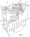
- a decapper 10 is designed to be compact enough to fit within an analytical instrument and preferably to form a component in a sample handler (not shown).
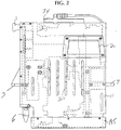
- Decapper 10 has a frame 11 comprising a front wall 18, right side wall 17, left side wall 19, and rear wall 20. Decapper 10 may be installed in the sample handler chassis (not shown) with decapper resting therein on supports 3, 4 on respective side walls 17, 19. Pins on the chassis may engage holes on supports 3, 4, such as hole 5 on support 4, and mounting pins 6 under the right side of decapper 10 to prevent frame 11 of decapper 10 from rotating. To easily clean and service decapper 10, decapper 10 is removable from the chassis where it is installed.
- decapper 10 The carrying of decapper 10 is made easier by the provision of a plurality of handles on frame 11, such as handles 1, 2.
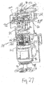
- An optional L-shaped cover 300 may be mounted to front wall 18 and overhang the decapper (Fig. 27).
- slots 220 are provided in front and rear walls 18, 20 (Figs. 1, 2).
- a decapping arm 12 is pivotably coupled to a drive shaft 14 (not shown) on a bidirectional DC motor (not shown), which may be coupled to a gear box to minimize the size of the required motor.
- the motor and gear box are encased within a steel tube 15 mounted to a support bar 16 extending between front and rear walls 18, 20.
- the selected combination of motor and gears should achieve a smooth, nonjerking and relatively quick motion and should be compact to fit within tube 15.
- An upper grippers 22 is mounted to the top of decapping arm 12 and a lower grippers 24 is mounted below upper grippers 22 to front and rear walls 18, 20.
- An armature 34 is also mounted to the top of plate 21 to hold an ultrasonic liquid level sensor 36 above upper grippers 22.
- a catch 27 is mounted between front and rear walls 18, 20 and above half-gears 130, 132.
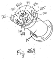
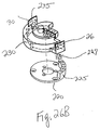
- Decapping arm 12 comprises a flat plate 21 mounted to a swing assembly 25, which in turn is mounted to drive shaft 14.
- swing assembly 25 comprises a socket 220 and clamp 230 that clamps to drive shaft 14 above socket 220 and decapping arm 12 is mounted directly to clamp 230.
- Socket 220 has an elevated section 225 that rises to approximately the height of clamp 230 and limits the rotation of decapping arm 12 to approximately a 90 degree rotation.
- a rubber stop 227 may be mounted on the side of elevated section 225 and a channel 235 may be left within clamp 230 to accommodate stop 227.
- a stationary end plate 240 is mounted above clamp 230 with ball bearings 250 surrounding drive shaft 14.
- End plate 240 serves as a mounting point on decapping arm 12 for an optional torsion spring 300 (Fig. 30) to bias decapping arm 12 in a closed position when the decapper is powered down so decapping arm 12 does not swing open when the decapper is removed from the instrument.
- the other mounting point for torsion spring 300 is elsewhere on a movable portion of decapping arm 12.
- FIGs. 1-25 illustrate an alternate embodiment of swing assembly 25 in which swing assembly 25 comprises a circular plate.
- the below description describes the decapper with the swing assembly 25 shown in Fig. 26A.
- decapping arm 12 is shown in a closed (or “decap") position wherein upper grippers 22 are located above lower grippers 24.
- decapping arm 12 is supported on the left side by tube 15 and on the right side of decapper 10 by a roller follower 29 mounted to the right side of decapping arm 12 that rides up along a ramp section of channel 27a in catch 27 and cams within catch 27 (Figs. 1, 3, 4B and 5).
- Roller 29 engages the bottom of channel 27a toward the front, wider section of channel 27a.
- roller 29 exerts a force against the bottom of channel 27a and thereby prevents the right side of decapping arm 12 from being pulled downward.
- roller 29 exerts a force against the top of channel 27a and thereby prevents decapping arm 12 from momentarily snapping upward.
- the cam on the right side of decapping arm 12 prevents decapping arm 12 from becoming deformed due to upward and downward forces during decapping.
- Decapping arm 12 is rotatable from the closed position to an open (or "waste") position shown in Fig. 3 by rotating decapping arm 12 ninety (90) degrees about shaft 14 to be perpendicular lengthwise to front and rear walls 18, 20. This causes upper grippers 22 to move as well to a position beyond front wall 18 rather than above lower grippers 24.
- the rotation of decapping arm 12 is driven by the aforementioned DC motor.
- a first flag 26 is mounted on clamp 220 and is positioned to enter sensor 28, which is preferably a hall effect sensor.
- sensor 28 is preferably a hall effect sensor.
- flag 26 rotates with clamp 220 out of sensor 28 and a second flag 30 on clamp 220 rotates into a second sensor 32, which is similar to sensor 28, when decapping arm 12 is in the open position, to provide a signal that decapping arm 12 is in the open position.
- the motor for decapping arm 12 slows to bring decapping arm 12 into the fully closed or open positions.
- Decapping arm 12 is held in the closed position with rod 23 against stop 27b and is held in the open position with clamp 220 against stop 227 by pulse width modulation to apply incremental pulses to hold decapping arm 12 in the desired position.
- Upper grippers 22 is shown in greater detail in the exploded view of Fig. 4A.
- Upper grippers 22 comprises three identical horizontal jaws 40-42 pivotably mounted to plate 21 at points 43-45, respectively, a rotatable wheel 46 which is coupled to jaws 40-42, a plate 48 mounted to the top of wheel 46, a rotatable arm 50, and a linkage 52 between arm 50 and plate 48.
- Jaws 40-42 are shown in Fig. 4A pivoted to an open position with teeth on each of jaws 40-42 recessed behind aperture 55 in plate 21 of decapping arm 12.
- Wheel 46 and plate 48 have apertures 56, 58, respectively, that are aligned above aperture 55 to provide clearance for a raised portion of a cap on a test tube.
- Apertures 55, 56, 58 are also aligned under sensor 36 for sensor 36 to read the liquid level of a test tube in lower grippers 24 aligned under apertures 55, 56, 58.
- Wheel 46 is rotatably mounted with bearings to locate wheel 46 slightly above jaws 40-42 so as not to interfere with the movement of the jaws.
- Bearings may consist of three equally spaced steel roller bearings 76-78 mounted to plate 21 on decapping arm 12 around the circumference of wheel 46.
- Wheel 46 has three arcuate slots 60-62.
- Jaws 40-42 are coupled to slots 60-62 on wheel 46 with respective roller followers 64, 70, 74.
- Slots 60-62 have a cam profile to cause roller followers 64, 70, 74 to translate jaws 40-42 so that the teeth thereon move inward above aperture 55 to grip a cap.
- Arm 50 is clamped to a drive shaft 80 extending from gear box 82, which is coupled to a bidirectional DC motor 84.
- the rotation of drive shaft 80 causes arm 50 to pivot and push or pull linkage 52, as appropriate, which in turn causes wheel 46 to rotate.
- wheel 46 is rotated fully clockwise, jaws 40-42 are in their recessed positions, as shown in Fig. 4. This is detected by a flag 86 on wheel 46 that enters a sensor 88, preferably a hall effect sensor, mounted to decapping arm 12 and overhanging wheel 46.
- Flag 86 rotates with wheel 46 to enter sensor 92, also preferably a hall effect sensor, mounted to decapping arm 12 when wheel 46 is fully turned.
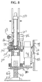
- a bracket 96 is mounted to a rail 99 with a bearing block 101 (Fig. 8), the particular bearing block being selected to minimize noise generated by travel of rotatable assembly 100 along rail 99.
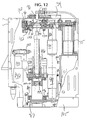
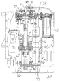
- Lower grippers 24 comprise a rotatable assembly 100 that moves up and down along lead screw 102 by activation of a motor 94 mounted adjacent rotatable assembly 100.
- Motor 94 is coupled to rotatable assembly 100 with a pulley 95 mounted to a shaft 93 on motor 94 which drives a timing belt 98 coupled to a circular section 97 having teeth on the bottom of rotatable assembly 100.
- Lead screw 102 is preferably threaded with a 4 mm pitch, which is the same pitch as the threading used on test tubes from most manufacturers (including Sarstedt and Braun) for twist-on caps. As a result, a single rotation of rotatable assembly 100 will unscrew screw-on caps from test tubes.
- Rotatable assembly 100 functions as a test tube holder having a base 104.
- the top of base 104 has a void 107 in the center of base 104 and a plate 111, having holes 113 through which liquid may pass, sits above void 107.
- Rotatable assembly 100 comprises two lever arms 106, 108 mounted to a shaft 105 mounted to base 104.
- Lever arms 106, 108 both pivot about shaft 105 and are spring-loaded with springs 110, 112, respectively, mounted to respective mounts 114, 116 into a closed position such that lever arms 106, 108 are essentially parallel to each other. This prevents the dropping of a test tube which is held between lever arms 106, 108 in the event of a power outage.
- a rubber pad 120, 122 with a high friction inner surface to grip test tubes securely is mounted to each of respective lever arms 106, 108.
- the high friction surface preferably has knobs 260 (Fig. 27) to grip the test tube securely even if there is liquid on the exterior of the test tube.
- a roller 118, 119 is mounted at the end of each respective lever arm 106, 108.
- a U-shaped reservoir 124 that has an outer wall and an open top is formed on the top of base 104 and at least under the location where test tubes are to be held between lever arms 106, 108.
- Reservoir 124 should be large enough to hold the entire liquid sample of the largest test tube that may be placed in decapper 10. Liquid passes through holes 113 in plate 111 and into void 107 that forms a smaller reservoir in base 104 where liquid is detected by a sensor 199.
- Two half-gears 130, 132 are mounted to pivot points 131, 133, respectively, on a fixed horizontal surface 134 that extends between front and rear walls 18, 20 to the right of rotatable assembly 100.
- Gears 130, 132 have teeth along the semi-circles 130a, 132a that defines the half-gears and have smooth edges 130b, 132b along the back of half-gears 130, 132.
- a pinion 136 is mounted to a drive shaft 138 of a motor 142 and gear box 140 mounted beneath half-gears 130, 132. In their initial retracted position, half-gears 130, 132 are rotated as shown in Fig.
- a semicircular flag 144 on gear 130 triggers a hall effect sensor 146 mounted adjacent pinion 136 when gears 130, 132 are fully retracted.
- a semicircular flag 145 on gear 132 passes through hall-effect sensor 147 when gears 130, 132 are retracted and, as flag 145 exits from sensor 147, motor 142 is stopped.
- the decapper according the present invention is designed to be an integral component within a sample handler of an automated instrument for decapping capped test tubes. Alternatively, it may be operated as a decapping station along a lab automation transport line, such as the LabCell transport line manufactured by the Bayer Corporation. In either of these two possibilities, a robotic arm (not entirely shown) may transport and insert individual test tubes into decapper 10 for decapping. One such robotic arm is described in the referenced Robotics application. Fingers 150 grip the test tube during transport. (Of course, decapper 10 could also be a stand-alone component into which capped test tubes are manually inserted for decapping, although this is not the preferred embodiment.)
- Decapper 10 is preferably controlled by an external controller, such as a controller based on the Intel 386EX microprocessor, which activates the motors for decapping arm 12, upper grippers 22, rotatable assembly 100 for lower grippers 24 and pinion 136, and communicates with the various sensors and motors on decapper 10 via an RS232 port which may be located on the right side of decapper 10 between mounting pins 6.
- an external controller such as a controller based on the Intel 386EX microprocessor, which activates the motors for decapping arm 12, upper grippers 22, rotatable assembly 100 for lower grippers 24 and pinion 136, and communicates with the various sensors and motors on decapper 10 via an RS232 port which may be located on the right side of decapper 10 between mounting pins 6.
- the decapper design of the preferred embodiment is particularly desirable where the sample handler has only a narrow space in which to mount decapper 12.
- decapping arm 12 In operation, when a capped test tube is to be decapped, that test tube is transported to decapper 10, such as with the robotic arm. Initially, when not in use, decapping arm 12 is either in the open or closed positions, rotatable assembly 100 is fully lowered along lead screw 102 (with flag 160 passing within sensor 162), and lever arms 106, 108 are closed. In preparation for the arrival of the test tube, decapping arm 12 is moved to its open position, if it is not already open, to expose lower grippers 24.
- rotatable assembly 100 of lower grippers 24, including base 104 and lever arms 106, 108 is rotated counterclockwise to move upward along lead screw 102 by activation of motor 94 and travels along rail 99 until lever arms 106, 108 are positioned at the same height as half-gears 130, 132 and are pointing toward right wall 17 of decapper 10.
- the vertical position of half-gears 130, 132 is programmed into the workstation software and tracked by a built-in homing mechanism and encoder for rotatable assembly 100 so the rotatable assembly 100 may be properly positioned.
- the proper positioning of rotatable assembly 100 is confirmed by a flag 168 on bracket 96 triggering a hall effect sensor 166 mounted along rail 99. (Fig. 8)
- motor 142 may be activated by the sample handler controller to rotate pinion 136 in a clockwise direction.
- the rotation of pinion 136 causes gear 130 to rotate in a counterclockwise direction and the rotation of gear 130 drives gear 132 to rotate clockwise.
- smooth edges 130b, 132b of gears 130, 132 push against rollers 118 and 119 on respective lever arms 106, 108, thereby pushing lever arms 106, 108 apart from one another against the force of springs 110 and 112.
- the test tube, held between fingers 150 on the robotic arm is then be inserted between rubber pads 120, 122 (Fig.
- the sample handler controller is preferably programmed to know the precise horizontal location on decapper 10 into which a test tube should be placed and how far the test tube held by the robotic arm must be lowered.
- An inertia switch (not shown) may be included on the robotic arm to stop the robotic arm if it detects that the test tube has been lowered too far and hit base 104 or any other element of decapper 10.
- the distance from the top of rubber pads 120, 122 on lever arms 106, 108 to the top of base 104 of rotatable assembly 100 in which the test tube sits is maintained to be a smaller distance than the height of the test tube located beneath the bottom of fingers 150 so that fingers do not interfere with the operation of lower grippers 24.
- the robotic arm should preferably always pick up the test tubes a set distance from the bottom of the test tube so that test tubes of various heights may be inserted into and decapped by decapper 10 without interfering with fingers 150. Decapper 10 should be configured to at least accommodate the tallest commonly-used test tube having the tallest cap.
- rotatable assembly 100 with the test tube held therein then rotates upwards until the top of the cap of the test tube is detected by sensor 170, after which rotatable assembly 100 rotates a fixed number of turns, based on the height of the cap, as determined by sensor 174 as explained below, and motor 94 is then turned off.
- Apertures 55 and 56 are tapered inward with an increasing elevation to accommodate the various shapes of available caps.
- apertures and aperture 58 allow caps with a raised central portion (such as the illustrated cap which is representative of the caps on test tubes made by Sarstedt of Germany) to be removed by this decapper as well.
- An outward taper in aperture 58 accomodates a nipple on the side of some Sarstedt caps.
- Two parallel sensors 172, 174 are mounted in a bracket 173 at a level above the level of sensor 170, each comprising a transmitter 172a, 174a, mounted adjacent motor 15, and a receiver 172b, 174b, mounted in a bracket 175 to the top of catch 27 to face transmitters 172a, 174a.
- Transmitter 172a is aligned to transmit a beam diagonally through the center of the axis centered within pads 120, 122B to detect caps with a raised central portion. If the test tube is capped, the cap will block the beam of sensor 172. If it is not capped, the beam will pass from transmitter 172a to receiver 172b uninterrupted.
- Sensor 174 is positioned approximately 6 mm away from sensor 172 and is used to detect a cap with a raised portion that is not centered on the cap. The cap information from sensors 172 and 174 is used to determine the type of cap and how many time rotatable assembly 100 must be rotated to raise the cap within upper grippers 22. Sensors 170, 174 will also detect whether a test tube without a cap was inserted into the decapper by mistake so that the uncapped test tube is not crushed by jaws 40-42 as they close to grip a cap of a test tube during the decapping process.
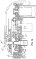
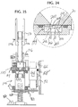
- motor 84 is activated and rotates arm 50 counterclockwise, thereby pulling linkage 52 and causing wheel 46 to rotate counterclockwise. (Figs. 15 and 16) This closes jaws 40-42 around the cap and holds the cap in place. Wheel 46 is prevented from fully turning by the engagement of jaws 40-42 against the cap.
- Motor 84 which is a servo motor, stops when it encounters the counteracting force on arm 50 generated when jaws 40-42 engage the cap.
- linkage 52 preferably comprises a spring-loaded cylinder 178a, a piston 178b placed within cylinder 178a, a torsion spring 178c, a socket 178d to hold spring within cylinder 178a and an eye 178e.
- spring-loaded 178a linkage 52 prevents linkage 52 from breaking as arm 50 causes jaws 40-42 to close against the cap by absorbing excess torque by temporarily compressing spring 178a.
- rotatable assembly 100 rotates downward in a clockwise direction, thereby both pulling downward on the cap while twisting the cap.
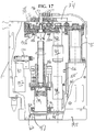
- This downward motion of rotatable assembly 100 unscrews and removes screw-on caps, such as the Sarstedt cap shown in Fig. 17 or a commonly-used HemaGuard® cap which also must be unscrewed to be removed.
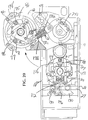
- This twisting and pulling motion also removes caps which must be pulled off, such as rubber stopper 190 which is removed as shown in Figs. 18, 19 by gripping cap 190 in a fixed position between jaws 40-42 and rotating rotatable assembly 100 downward.
- This motion also decaps test tubes having any other type of cap which may be removed with a twisting motion. If the cap is not properly removed, this will be detected by sensor 170, which will prevent decapping arm 12 returning to the closed position to determine the liquid level in the test tube and hitting the cap.
- a disposable protective cover 270 having a central aperture 275 for the test tube, is mounted to the top of rotatable assembly (Figs. 27A and 27B).
- Protective cover 270 may be made of plastic and may be disposed of and replaced as part of a regular cleaning program for decapper 10.
- rotatable assembly 100 After removing the cap, rotatable assembly 100 is rotated fully downward on lead screw 102 as indicated by the encoder on motor 94. The position of rotatable assembly 100 is confirmed by a flag 160 that triggers sensor 162. This provides a reference position in which the liquid level may be read. Decapping arm 12 then rotates to its open position while continuing to grip the removed cap.
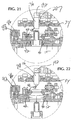
- Figs. 20, 21 When sensor 32 detects that the decapping arm is in the decapping position, motor 84 is activated to rotate wheel 46 clockwise, which retracts jaws 40-42 and releases the removed cap.
- a waste container (not shown) may be positioned underneath upper grippers 22 when the decapping arm 12 is in the open position to catch the removed caps for disposal. Alternatively, the caps may be collected and used to recap the tubes with appropriate caps at a later time.
- Decapping arm 12 next returns to the closed position with ultrasonic liquid level sensor 36 now positioned directly above the test tube still held by lower grippers 24.
- Sensor 36 sits in a sensor holder 192, which is a non-metallic swivel-type bracket which permits sensor 36 to be adjusted toward the surface of the liquid in the test tube.
- Sensor 36 is gimbaled within a gimbal 287 (Fig. 32) that sits within sensor holder 192 to self-align (Fig. 33) sensor 36 if instrument becomes misaligned and sensor 36 is held by sensor holder 192 above the transducer so as not to interfere with the ringing of the transducer with or limit the beam shape of the ultrasonic burst.
- Sensor holder 192 is adjusted to be properly aligned and is tightened with two set screws 280, 281 to armature 34 (Fig. 27).
- Sensor holder 192 is aligned to point sensor 36 perpendicularly to the liquid in the test tube.
- Ultrasonic liquid level sensor 36 must be able to detect the liquid level within a short range from sensor 36. Because sensor 36 is unable to receive and detect echoes while sensor 36 is ringing, a dead zone is create adjacent sensor 36 through which the ultrasonic burst propagates before sensor 36 is able to detect echoes. Echoes reflected from a surface in the dead zone will not be detected at sensor 36. To avoid dead zone problems, sensor 36 is mounted at least approximately 1 inch from the top of the tallest test tube, which is 100 mm in height.
- sensor 36 is preferably a Cosense sensor Part No. 123-10001.
- Sensor 36 has a transducer which is 0.25 inches in diameter and approximately 0.75 inches in length.
- a pulse having a frequency of approximately 1.0 MHz and a pulse width of approximately 1 microsecond is applied to sensor 36, causing sensor 36 to ring possibly as long as, but not longer than, 100 microseconds.
- the high ultrasonic frequency of 1.0 MHz is used (typically ultrasonic sensors are operated in the kHz range) to reduce the length of ringing of the transducer, thereby minimizing the size of the dead zone.
- sensor holder 192 is nonmetallic so as not to extend the length of time the transducer rings. Leaving 1 inch between the dead zone and the tallest test tube and with sensor 36 having the given dimensions and operated at the specified frequency yields a sensing range of approximately 5 inches. To accommodate the required sensing range, sensor 90 should be mounted approximately 5 inches above the lowest point on which the test tube will rest, viz., on top of plate 111. The liquid level of the sample within the test tube is captured and transmitted to the sample handler controller or another external controller which requires the liquid level information.
- Sensor 36 may be identical to and operated with the same operating conditions as the ultrasonic sensor used in the referenced application entitled Dynamic Noninvasive Detection of Analytical Container Features Using Ultrasound.
- the profiling described in that application may be used to determine at an earlier stage in the sample handler whether or not a test tube is capped. If the test tube is capped, it is sent to decapper 12 to be decapped.
- test tube is removed from the decapper.
- decapping arm 12 is moved to the open position, the robotic arm returns to grip the now-uncapped test tube, and after a handshake between the robotic arm and decapper, lever arms 106, 108 are pushed apart by half-gears 130, 132 as described above. The robotic arm may then transport the test tube elsewhere.
- Sensor 199 comprises an upper area 201, into which liquid from void 107 passes, prism 200, which may be comprised of optical glass, and two fiber optic cables 202, 204 pointing perpendicularly upward. Light is transmitted through fiber optic cable 202, as shown by arrow 206, and is incident on the side 207 of prism 200. If there is no liquid in the bottom of reservoir 124, the light incident on side 207 continues its upward travel and is not reflected.
- decapper 10 is capable of decapping a variety of caps from test tubes of different types and various heights and diameters.
- decapper 10 is a component in a sample handler
- it may be used to reseat uncapped test tubes which are fed into the sample handler on racks but are not properly seated within the rack.
- the liquid level cannot be correctly measured by a liquid level sensor elsewhere in the sample handler because the liquid level measurement is made using a reference point set by the rack.
- test tube may be extracted from elsewhere in the sample handler by the robotic arm and transported to the decapper where the robotic arm seats the container properly within lower grippers 24.
- the sample handler controller instructs the decapper not to decap the test tube but does read the liquid level of the now properly seated test tube.
Landscapes
- Engineering & Computer Science (AREA)
- Mechanical Engineering (AREA)
- Automatic Analysis And Handling Materials Therefor (AREA)
- Devices For Opening Bottles Or Cans (AREA)
- Cleaning By Liquid Or Steam (AREA)
- Investigating Or Analyzing Materials By The Use Of Ultrasonic Waves (AREA)
Abstract
Description
Claims (14)
- An automatic decapper for removing a cap from a test tube, said decapper comprising:upper grippers having a first position to grip said cap and maintain said cap in a stationary position,lower grippers having a first position to grip said test tube spaced from said upper grippers, andmeans for rotating said lower grippers relative to and translated away from said upper grippers while said upper grippers hold said cap stationary and said lower grippers grip said test tube to remove said cap from said test tube.
- The decapper of claim 1 wherein said rotating means comprise a rotatable assembly and a lead screw, said lower grippers being mounted on the rotatable assembly, the rotatable assembly being coupled to the lead screw over which said rotatable assembly may be rotated and translated.
- The decapper of claim 1 further comprising a decapping arm to which said upper grippers are mounted, wherein said decapping arm is pivotable between a first position above said lower grippers in which said test tube may be decapped and a second position which provides clearance adjacent said lower grippers to allow said test tube to be inserted into or removed from said lower grippers or to release a removed cap for disposal.
- An automatic decapper for removing a cap from a test tube, said decapper comprisingupper grippers for gripping said cap, said upper grippers comprisinga rotatable disk having a plurality of arcuate slots,a plurality of retractable jaws coupled to said slots in said disk such that said jaws pivot to a gripping position to grip said cap with said jaws during decapping of said test tube and said jaws pivot to a retracted position when it is not desired to grip said cap, andmeans for rotating said disk to move said jaws between said retracted position and said gripping position,lower grippers for gripping said test tube, andmeans for moving said lower grippers relative to said upper grippers to remove said cap from said test tube.
- The decapper of claim 0 further comprising a decapping arm to which said upper grippers are mounted, wherein said decapping arm is pivotable between a first position above said lower grippers in which said test tube may be decapped and a second position which provides clearance adjacent said lower grippers to allow said test tube to be inserted into or removed from said lower grippers or to release a removed cap for disposal.
- The decapper of claim 5 wherein said means for moving said lower grippers relative to said upper grippers to remove said cap from said test tube comprises means for rotating and translating said lower grippers downward while said upper grippers hold said cap stationary.
- The decapper of claim 6 further comprisingan assembly having a first side, a second side and a pivot point, the assembly pivot point being coupled to said decapping arm, the decapping arm pivoting to move between said first and second positions, said pivot point being located toward the first side of said decapping arm,a channel located above said lower grippers and adjacent the second side of said decapping arm opposite to said first side when said decapping arm is in said first position, anda cam on said second side of said decapping arm, said cam engagable with said channel when said decapping arm is in said first position to provide support for said decapping arm on said second side when said lower grippers are moved relative to said upper grippers.
- The decapper of claim 5 wherein said decapping arm has a first aperture and said cap has an outer circumference and a raised central portion within said outer circumference, and said rotatable disk further comprises a second aperture located above said first aperture, and said decapper further comprises an armature for positioning an ultrasonic sensor above said first and second apertures and said test tube when said decapping arm is returned to said first position after said test tube has been decapped to determine a height level of a sample in said test tube.
- An automatic decapper for removing a cap from a test tube, said decapper comprisingupper grippers for gripping said cap,lower grippers for gripping said test tube, said lower grippers comprising a pair of lever arms biased together toward a closed position to grip said test tube when said test tube is inserted therebetween,a pair of half-gears that are rotatable to push apart said pair of lever arms from said closed position to an open position to accept or release a test tube when said pair of lever arms are adjacent said half-gears, andmeans for moving said lower grippers relative to said upper grippers to remove said cap from said test tube.
- The decapper of claim 9 wherein said upper grippers hold said cap stationary therein and said means for moving said lower grippers comprises a rotatable assembly to which said lower grippers is mounted and which is coupled to a lead screw over which said rotatable assembly may be rotated and translated downward.
- A method for removing a cap from a capped test tube with a decapper comprising upper grippers, said upper grippers having a first position to permit the insertion of a cap between said upper grippers and a second position to grip said cap, and lower grippers to grip said test tube located under said upper grippers, said method comprising:gripping said test tube with said lower grippers,inserting said cap within said upper grippers while said upper grippers are in said first position;gripping said cap by moving said upper grippers to said second position, andremoving said cap from said test tube by rotating and translating said lower grippers away from said upper grippers.
- The method of claim 11 wherein said decapper further comprises a pivotable decapping arm to which said upper grippers are mounted, said decapping arm having a first position in which said upper grippers are located adjacent said lower grippers and a second position in which said upper grippers provide clearance adjacent said lower grippers to allow the insertion or removal of said test tube from said lower grippers, said method further comprising:before gripping said test tube, pivoting said decapping arm from said first position to said second position and inserting said test tube within said lower grippers, andafter gripping said test tube, rotating and translating said lower grippers away from said first position of said decapping arm and pivoting said decapping arm back to said first position, and
wherein said step of inserting said cap into said upper grippers comprises rotating and translating said lower grippers to insert said cap of said capped test tube into said upper grippers. - The method of claim 12 wherein said decapper further comprises an ultrasonic sensor located adjacent said uncapped test tube to measure a level of a sample in said test tube, and said method further comprises measuring said level of said sample using said ultrasonic sensor after said cap has been removed from said test tube.
- A sensor to detect the presence of liquid in a reservoir having a bottom, said sensor comprising a prism having a first side mounted flush with the bottom of said reservoir, and having second and third sides, a first fiber optic cable to transmit light into said prism, said first fiber optic cable having a first end directed normal to said first side of said prism and toward said second side of said prism, and a second fiber optic cable to receive at least a portion of said light transmitted into said prism when said liquid is present in said reservoir, said second fiber optic cable having a first end directed normal to said first side of said prism and toward said third side of said prism.
Applications Claiming Priority (2)
| Application Number | Priority Date | Filing Date | Title |
|---|---|---|---|
| US09/115,777 US6257091B1 (en) | 1998-07-14 | 1998-07-14 | Automatic decapper |
| US115777 | 2002-04-03 |
Publications (2)
| Publication Number | Publication Date |
|---|---|
| EP0972744A2 true EP0972744A2 (en) | 2000-01-19 |
| EP0972744A3 EP0972744A3 (en) | 2000-08-02 |
Family
ID=22363329
Family Applications (1)
| Application Number | Title | Priority Date | Filing Date |
|---|---|---|---|
| EP99112800A Withdrawn EP0972744A3 (en) | 1998-07-14 | 1999-07-02 | Automatic decapper |
Country Status (7)
| Country | Link |
|---|---|
| US (1) | US6257091B1 (en) |
| EP (1) | EP0972744A3 (en) |
| JP (1) | JP2000039438A (en) |
| AU (1) | AU756300B2 (en) |
| BR (1) | BR9902719A (en) |
| CA (1) | CA2274226A1 (en) |
| NO (1) | NO993158L (en) |
Cited By (24)
| Publication number | Priority date | Publication date | Assignee | Title |
|---|---|---|---|---|
| EP1195609A3 (en) * | 2000-10-06 | 2005-05-11 | Mettler-Toledo GmbH | Analyzer with apparatus for opening sample covers |
| EP1659091A1 (en) * | 2004-11-23 | 2006-05-24 | Kordia B.V. | Device for removing caps from test tubes |
| EP1659090A1 (en) * | 2004-11-23 | 2006-05-24 | Kordia B.V. | Method and apparatus for detecting caps on test tubes |
| WO2008067844A1 (en) * | 2006-12-04 | 2008-06-12 | Inpeco Ip Ltd. | Apparatus for removing caps from tubular containers |
| CN100460309C (en) * | 2004-05-14 | 2009-02-11 | 株式会社Ids | Cap removing apparatus for removing cap from tube-like container |
| WO2008078304A3 (en) * | 2006-12-22 | 2009-07-30 | Esposti Filippo Degli | Automatic sampling apparatus for chemical analyses with a guide device for the sample collecting/injecting |
| EP1508048A4 (en) * | 2002-05-28 | 2009-11-04 | Autogenomics Inc | Level-controlled pipette for automated analytic devices |
| US20090324032A1 (en) * | 2008-06-25 | 2009-12-31 | Jadak Llc | System and Method For Test Tube and Cap Identification |
| CN101798048A (en) * | 2010-03-17 | 2010-08-11 | 珠海倍健电子科技有限公司 | Control system for full-automatic vacuum test tube uncapping machine |
| CN102050413A (en) * | 2009-11-04 | 2011-05-11 | 株式会社日立高新技术 | Cover opener and automatic analyzing device using same |
| DE102011081748A1 (en) | 2011-08-29 | 2013-02-28 | Hamilton Bonaduz Ag | Device for automated opening of containers with screw cap |
| WO2014020168A1 (en) | 2012-08-03 | 2014-02-06 | Hamilton Bonaduz Ag | Device for establishing and disestablishing threaded connections in an automated manner |
| CN104058356A (en) * | 2014-06-24 | 2014-09-24 | 天津海迈医用科技有限公司 | Uncapping machine with function of automatically uncapping single blood collection tube |
| EP2842629A1 (en) * | 2013-08-27 | 2015-03-04 | F. Hoffmann-La Roche AG | Device for reading of an identification code carried by tubular containers using a tube rotator |
| CN104692307A (en) * | 2014-12-30 | 2015-06-10 | 山东省千佛山医院 | Decapping device for vacuum blood collection tube |
| EP2886508A1 (en) | 2013-12-20 | 2015-06-24 | CTC Analytics AG | Actuating device for screw-on cap |
| CN108640067A (en) * | 2018-05-10 | 2018-10-12 | 张汀仁 | A kind of medical saline bottle processing medical instrument robot |
| CN109110705A (en) * | 2018-06-27 | 2019-01-01 | 毛静玲 | A kind of bottled drink automatic lid closing/opening heating device |
| CN110835076A (en) * | 2019-10-31 | 2020-02-25 | 江苏新美星包装机械股份有限公司 | Directional capping method |
| CN114835072A (en) * | 2022-05-27 | 2022-08-02 | 中元汇吉生物技术股份有限公司 | Uncovering device and control method thereof |
| EP4335798A4 (en) * | 2021-06-03 | 2024-07-24 | Beijing Huironghe Technology Co., Ltd | TEST TUBE CAP SCREWING DEVICE |
| US12210030B2 (en) | 2019-05-03 | 2025-01-28 | Gen-Probe Incorporated | Receptacle transport system for an analytical system |
| EP4252908A4 (en) * | 2020-12-07 | 2025-02-19 | Bioneer Corporation | ADAPTER FOR MOUNTING A CONDUCTIVE PIPETTE, DEVICE FOR OPENING/CLOSING SAMPLE TUBES, AND AUTOMATIC SAMPLE ANALYSIS SYSTEM |
| US12698193B2 (en) | 2023-07-10 | 2026-08-04 | Express Scripts Strategic Development, Inc. | Decapper |
Families Citing this family (62)
| Publication number | Priority date | Publication date | Assignee | Title |
|---|---|---|---|---|
| US6871566B2 (en) * | 2001-09-20 | 2005-03-29 | Aloka Co., Ltd. | Cap opening system and method for opening cap |
| JP2005506538A (en) * | 2001-10-19 | 2005-03-03 | モノジェン インコーポレイテッド | Article handling system and method |
| US6912931B1 (en) * | 2002-03-25 | 2005-07-05 | Innovating Solutions, Inc. | Method and apparatus for removing a lid from a container |
| DE20310332U1 (en) * | 2003-07-04 | 2004-11-11 | Mwg-Biotech Ag | Device for automatic opening and closing of reaction vessels |
| JP2005075395A (en) * | 2003-08-29 | 2005-03-24 | Teruaki Ito | Test tube plug remover |
| JP3860178B2 (en) * | 2004-04-05 | 2006-12-20 | 株式会社アイディエス | Bar code reader for test tubes |
| EP2156196B1 (en) * | 2007-04-06 | 2020-12-23 | Becton, Dickinson and Company | Sample preparation system for processing of clinical specimens |
| US7985375B2 (en) * | 2007-04-06 | 2011-07-26 | Qiagen Gaithersburg, Inc. | Sample preparation system and method for processing clinical specimens |
| US8357538B2 (en) * | 2007-04-06 | 2013-01-22 | Qiagen Gaithersburg, Inc. | Automated assay and system |
| US8703492B2 (en) | 2007-04-06 | 2014-04-22 | Qiagen Gaithersburg, Inc. | Open platform hybrid manual-automated sample processing system |
| US7409809B1 (en) | 2007-04-10 | 2008-08-12 | Lars Degen | Automatic test tube decapping device |
| EP2282212B1 (en) * | 2008-05-22 | 2018-11-28 | Hitachi High-Technologies Corporation | System for pretreating sample |
| US8297151B1 (en) * | 2009-01-17 | 2012-10-30 | Joseph Huppenthal | Apparatus for opening and closing a specimen vial |
| US9953141B2 (en) | 2009-11-18 | 2018-04-24 | Becton, Dickinson And Company | Laboratory central control unit method and system |
| CN102145872B (en) * | 2011-01-19 | 2013-05-01 | 南京航空航天大学 | Automatic screwing assembling machine for plastic split bottle cap |
| EP2538225A1 (en) * | 2011-06-20 | 2012-12-26 | F. Hoffmann-La Roche AG | System for processing closed sample tubes |
| EP3225972B1 (en) | 2011-09-09 | 2025-03-19 | Gen-Probe Incorporated | Automated sample handling method |
| US9381524B2 (en) | 2011-11-08 | 2016-07-05 | Becton, Dickinson And Company | System and method for automated sample preparation |
| US9199755B1 (en) * | 2012-02-11 | 2015-12-01 | Joseph Cohen | Apparatus and methods for handling tubes or vials |
| US12157595B2 (en) * | 2012-05-03 | 2024-12-03 | Vanrx Pharmasystems Inc. | Cover removal system for use in controlled environment enclosures |
| US12065347B2 (en) | 2012-05-03 | 2024-08-20 | Vanrx Pharmasystems Inc. | Cover removal system for use in controlled environment enclosures |
| JP6170165B2 (en) | 2012-10-16 | 2017-07-26 | ベックマン コールター, インコーポレイテッド | Chute configuration with peeling mechanism |
| CN104386629B (en) * | 2014-09-22 | 2016-06-29 | 深圳市奥特库贝科技有限公司 | A kind of novel agent bottle automatically opening and closing mechanism |
| CN104444983B (en) * | 2014-12-04 | 2016-08-24 | 威海百博医疗智能机器人有限公司 | Sample tube goes to close the lid and Handling device automatically |
| WO2016104666A1 (en) * | 2014-12-26 | 2016-06-30 | テルモ株式会社 | Liquid transport method |
| WO2016130962A1 (en) | 2015-02-13 | 2016-08-18 | Abbott Laboratories | Automated storage modules for diagnostic analyzer liquids and related systems and methods |
| EP3368465A1 (en) | 2015-10-27 | 2018-09-05 | Hamilton Storage Technologies, Inc. | Automated bit exchange for laboratory sample tube capping and decapping machines |
| EP3236267B1 (en) | 2016-04-18 | 2021-09-08 | Roche Diagnostics GmbH | Decapper and apparatus |
| EP3388839B1 (en) * | 2017-04-10 | 2023-08-30 | F. Hoffmann-La Roche AG | Centering unit for diagnostics laboratory transporting compartment |
| CN107167216B (en) * | 2017-05-20 | 2019-07-05 | 浙江达普生物科技有限公司 | It is a kind of to detect accurate blood plasma and haemocyte interface identification device |
| CN107904833B (en) * | 2017-12-20 | 2023-08-25 | 南通亿思特机器人科技有限公司 | Yarn dyeing rubber tube treatment equipment |
| WO2020017408A1 (en) * | 2018-07-17 | 2020-01-23 | 国立大学法人神戸大学 | Cap attaching/detaching device, and sampling device and pre-processing device provided with same |
| CN109439545B (en) * | 2018-11-07 | 2024-09-10 | 深圳大学 | Biomedical experimental equipment |
| CN109592620B (en) * | 2018-12-29 | 2023-08-29 | 天津森雅医疗设备科技有限公司 | Tray cover opening device of intelligent medicine dispensing terminal |
| CN109436764B (en) * | 2018-12-29 | 2023-10-27 | 天津森雅医疗设备科技有限公司 | Tray opening and closing medicine receiving device for medicine dispensing terminal |
| CN110531096B (en) * | 2019-09-29 | 2024-01-26 | 青岛中特环保仪器有限公司 | Fully automatic water quality COD robot analyzer |
| EP4051622B1 (en) * | 2019-10-29 | 2026-04-29 | Beckman Coulter, Inc. | Sample tube decapper |
| CN110849754B (en) * | 2019-11-26 | 2022-02-25 | 滨州职业学院 | Non-equal-frequency intermittent transfer and replacement device for concrete hardness detection |
| CN111591939A (en) * | 2020-04-23 | 2020-08-28 | 四川省环宇众冠科技发展有限公司 | A test tube capping machine and its capping method |
| CN111732046B (en) * | 2020-07-24 | 2024-08-27 | 天津海迈医用科技有限公司 | Automatic cap opening machine for medical blood collection tube |
| WO2022025924A1 (en) * | 2020-07-31 | 2022-02-03 | Baxalta Incorporated | Grip detection system for liquid handling robot |
| CN112027996A (en) * | 2020-08-05 | 2020-12-04 | 宁波熠辉医疗科技有限公司 | Full-automatic test tube uncaps equipment |
| CN114074907B (en) * | 2020-08-12 | 2024-08-09 | 江苏天瑞仪器股份有限公司 | Test tube uncapping and closing device |
| CN114436184B (en) * | 2020-10-30 | 2024-11-29 | 深圳市瑞图生物技术有限公司 | Cap pulling device and sample analyzer |
| EP4043887B1 (en) * | 2021-02-15 | 2023-11-15 | Roche Diagnostics GmbH | Decapper for removing a cap from a laboratory sample container |
| US20230258673A1 (en) * | 2021-03-17 | 2023-08-17 | Hangzhou Bioer Technology Co., Ltd. | Full-automatic gene analysis apparatus and gene analysis method |
| CN113325167B (en) * | 2021-05-24 | 2023-04-14 | 四川省信捷迅科技有限公司 | Automatic detection equipment |
| CN113548615A (en) * | 2021-06-19 | 2021-10-26 | 江苏迅睿生物技术有限公司 | Cap screwing method |
| CN113307205A (en) * | 2021-07-12 | 2021-08-27 | 安图实验仪器(郑州)有限公司 | Automatic cup cover screwing device |
| CN113955692B (en) * | 2021-10-09 | 2023-06-20 | 阳普医疗科技股份有限公司 | Cover pulling mechanism of thromboelastography instrument |
| CN113800450B (en) * | 2021-10-18 | 2023-04-28 | 山东康华生物医疗科技股份有限公司 | Cover opening and closing device for full-automatic blood sampling tube |
| CN114082463B (en) * | 2021-11-22 | 2022-12-09 | 郑州大学第一附属医院 | A system and method for intelligent processing of neurology samples |
| CN116265375B (en) * | 2021-12-16 | 2025-04-11 | 青岛海尔生物医疗科技有限公司 | Tank cover opening device for liquid nitrogen tank |
| CN114247352B (en) * | 2021-12-21 | 2024-05-10 | 广州蓝勃生物科技有限公司 | Test tube shaking device |
| EP4458755A4 (en) * | 2021-12-29 | 2025-12-10 | Autobio Labtec Instr Co Ltd | ONLINE UNCAP SYSTEM |
| CN114314472A (en) * | 2021-12-29 | 2022-04-12 | 安图实验仪器(郑州)有限公司 | Sample tube uncovering device |
| CN115043367A (en) * | 2022-05-30 | 2022-09-13 | 深圳瑞智捷医疗科技有限公司 | A test tube automatic cap removal machine and control method thereof |
| CN114832699B (en) * | 2022-07-06 | 2022-09-06 | 昆明理工大学 | Cell culture is with shaking mixing arrangement |
| CN115504213B (en) * | 2022-09-04 | 2024-10-18 | 百福泰(青岛)防护科技有限公司 | Automatic collecting system that breaks off with fingers and thumb of throat swab cotton swab head |
| CN115535938B (en) * | 2022-10-11 | 2025-08-12 | 江苏科技大学 | Cap opening and buckling machine for medical test tube |
| CN116002593B (en) * | 2023-01-04 | 2025-10-21 | 洛阳中联国展新材料有限公司 | Sample box opening and closing equipment |
| CN116872211B (en) * | 2023-08-04 | 2025-10-17 | 四川徕伯益自动化技术有限公司 | Mechanical claw control method and system |
Family Cites Families (39)
| Publication number | Priority date | Publication date | Assignee | Title |
|---|---|---|---|---|
| US1424607A (en) * | 1921-05-31 | 1922-08-01 | Wisenberg Don Carlos | Article holder |
| US2524434A (en) * | 1947-11-25 | 1950-10-03 | Henry T Duket | Multiple jaw jar cap wrench |
| US3229553A (en) * | 1961-03-21 | 1966-01-18 | Leslie B Fredrickson | Bottle cap opener |
| US3589103A (en) | 1968-06-22 | 1971-06-29 | Luis B Calvillo | Machines for unscrewing caps or stoppers from containers |
| FR1594399A (en) | 1968-12-12 | 1970-06-01 | ||
| IL32989A (en) * | 1969-09-11 | 1972-07-26 | Anati R | A wrench |
| DE2212659C3 (en) | 1972-03-16 | 1979-08-09 | Datz, Hermann, Dr.Rer.Pol., 5470 Andernach | Device for removing screw caps from bottles and similar containers |
| US3803795A (en) | 1973-01-26 | 1974-04-16 | J Ouellette | Closure removing apparatus and method |
| US3844093A (en) | 1973-04-26 | 1974-10-29 | Dacam Corp | Apparatus for decapping bottles |
| US3852867A (en) | 1973-07-09 | 1974-12-10 | G Risener | Bottle decapping system |
| US3914920A (en) | 1974-05-06 | 1975-10-28 | Carling O Keefe Ltd | Decapping device for the decapping of bottles |
| US3987535A (en) | 1975-07-31 | 1976-10-26 | Brown Winton F | Bottle decapping method and apparatus |
| US4172397A (en) | 1975-12-05 | 1979-10-30 | Metal Closures Limited | Machine for de-capping containers |
| DE2610209A1 (en) | 1976-03-11 | 1977-09-22 | Marvin Glass & Associates | Adjustable vessel and tin opening appts. - has housing with rotating mounting plate and column with adjustable clamp for domestic use |
| US4030271A (en) | 1976-06-11 | 1977-06-21 | The United States Of America As Represented By The Secretary Of The Department Of Health, Education And Welfare | Apparatus for capping and uncapping containers |
| GB1518492A (en) | 1977-02-04 | 1978-07-19 | Ford Motor Co | Liquid level warning device |
| US4171650A (en) | 1977-12-09 | 1979-10-23 | John Cardinal | Jar lid loosening device |
| US4178732A (en) | 1978-04-21 | 1979-12-18 | Pfleger Frederick W | Apparatus for closing and opening the threaded necks of containers |
| US4217798A (en) | 1979-04-30 | 1980-08-19 | The United States Of America As Represented By The Department Of Health, Education And Welfare | Automated test tube stopper remover |
| US4522089A (en) | 1983-10-28 | 1985-06-11 | Alvi Javid R | Test tube cap remover |
| US4620411A (en) | 1985-04-01 | 1986-11-04 | Liqui-Box Corporation | Filler for bags connected in a continuous strip |
| US4676712A (en) | 1985-06-19 | 1987-06-30 | Hayward Milton L | Positioning and locking apparatus |
| US4773285A (en) | 1985-10-29 | 1988-09-27 | Labatt Brewing Company Limited | Automatic decapper |
| JPH0338704Y2 (en) | 1986-04-30 | 1991-08-15 | ||
| US4935621A (en) | 1987-10-30 | 1990-06-19 | Pikulski Joseph L | Optical switch with collimating lenses, antifreeze and/or index matching fluid for control of electrical equipment |
| US5080864A (en) | 1990-07-20 | 1992-01-14 | Eastman Kodak Company | Stopper detector |
| US5380486A (en) | 1991-04-19 | 1995-01-10 | Olympus Optical Co., Ltd. | Apparatus for taking liquid content for use in analysis out of container |
| US5366896A (en) | 1991-07-30 | 1994-11-22 | University Of Virginia Alumni Patents Foundation | Robotically operated laboratory system |
| JPH05221487A (en) | 1992-04-23 | 1993-08-31 | Nittec Co Ltd | Transfer device of container |
| US5340544A (en) * | 1992-06-22 | 1994-08-23 | System Stack Co., Ltd. | Plug-opening device for a specimen container |
| US5345844A (en) | 1993-04-12 | 1994-09-13 | Marsaw Morris R | Jar lid opener apparatus |
| US5481946A (en) * | 1993-05-14 | 1996-01-09 | System Stack, Co., Ltd. | Plug-opening device for sealed container |
| US5370019A (en) | 1994-01-10 | 1994-12-06 | Sartell; M. Kevin | Jar lid remover |
| JP2955613B2 (en) | 1994-09-21 | 1999-10-04 | 株式会社日立製作所 | Analysis equipment |
| US5507178A (en) | 1994-11-09 | 1996-04-16 | Cosense, Inc | Liquid presence and identification sensor |
| US5623415A (en) | 1995-02-16 | 1997-04-22 | Smithkline Beecham Corporation | Automated sampling and testing of biological materials |
| DE19512905A1 (en) | 1995-04-06 | 1996-10-10 | Boehringer Mannheim Gmbh | Device for pulling or unscrewing closures from vessels |
| US5735181A (en) | 1996-03-05 | 1998-04-07 | Anderson; Arthur G. | Apparatus for removing a safety cap from a safety container |
| US5784933A (en) * | 1996-12-19 | 1998-07-28 | Persellin; Avram | Apparatus for removing a threaded cap from a container |
-
1998
- 1998-07-14 US US09/115,777 patent/US6257091B1/en not_active Expired - Lifetime
-
1999
- 1999-06-10 CA CA002274226A patent/CA2274226A1/en not_active Abandoned
- 1999-06-16 AU AU35080/99A patent/AU756300B2/en not_active Ceased
- 1999-06-25 NO NO993158A patent/NO993158L/en not_active Application Discontinuation
- 1999-07-02 EP EP99112800A patent/EP0972744A3/en not_active Withdrawn
- 1999-07-12 BR BR9902719-4A patent/BR9902719A/en not_active Application Discontinuation
- 1999-07-13 JP JP11199307A patent/JP2000039438A/en active Pending
Cited By (43)
| Publication number | Priority date | Publication date | Assignee | Title |
|---|---|---|---|---|
| EP1195609A3 (en) * | 2000-10-06 | 2005-05-11 | Mettler-Toledo GmbH | Analyzer with apparatus for opening sample covers |
| EP1508048A4 (en) * | 2002-05-28 | 2009-11-04 | Autogenomics Inc | Level-controlled pipette for automated analytic devices |
| CN100460309C (en) * | 2004-05-14 | 2009-02-11 | 株式会社Ids | Cap removing apparatus for removing cap from tube-like container |
| EP1659091A1 (en) * | 2004-11-23 | 2006-05-24 | Kordia B.V. | Device for removing caps from test tubes |
| EP1659090A1 (en) * | 2004-11-23 | 2006-05-24 | Kordia B.V. | Method and apparatus for detecting caps on test tubes |
| CN101568386B (en) * | 2006-12-04 | 2012-03-07 | 英派克埃彼有限公司 | Apparatus for removing caps from tubular containers |
| WO2008067844A1 (en) * | 2006-12-04 | 2008-06-12 | Inpeco Ip Ltd. | Apparatus for removing caps from tubular containers |
| US8220137B2 (en) | 2006-12-04 | 2012-07-17 | Inpeco Ip Ltd. | Apparatus for removing caps from tubular containers |
| WO2008078304A3 (en) * | 2006-12-22 | 2009-07-30 | Esposti Filippo Degli | Automatic sampling apparatus for chemical analyses with a guide device for the sample collecting/injecting |
| US8170271B2 (en) * | 2008-06-25 | 2012-05-01 | Jadak Llc | System and method for test tube and cap identification |
| US20090324032A1 (en) * | 2008-06-25 | 2009-12-31 | Jadak Llc | System and Method For Test Tube and Cap Identification |
| CN102050413A (en) * | 2009-11-04 | 2011-05-11 | 株式会社日立高新技术 | Cover opener and automatic analyzing device using same |
| CN102050413B (en) * | 2009-11-04 | 2013-08-07 | 株式会社日立高新技术 | Cover opener and automatic analyzing device using same |
| CN101798048B (en) * | 2010-03-17 | 2011-10-26 | 珠海倍健电子科技有限公司 | Control system for full-automatic vacuum test tube uncapping machine |
| CN101798048A (en) * | 2010-03-17 | 2010-08-11 | 珠海倍健电子科技有限公司 | Control system for full-automatic vacuum test tube uncapping machine |
| DE102011081748A1 (en) | 2011-08-29 | 2013-02-28 | Hamilton Bonaduz Ag | Device for automated opening of containers with screw cap |
| WO2013030196A1 (en) | 2011-08-29 | 2013-03-07 | Hamilton Bonaduz Ag | Device for the automated opening of containers with a screw closure |
| WO2014020168A1 (en) | 2012-08-03 | 2014-02-06 | Hamilton Bonaduz Ag | Device for establishing and disestablishing threaded connections in an automated manner |
| DE102012213821A1 (en) | 2012-08-03 | 2014-02-06 | Hamilton Bonaduz Ag | Device for automated production and release of screw connections |
| EP2842629A1 (en) * | 2013-08-27 | 2015-03-04 | F. Hoffmann-La Roche AG | Device for reading of an identification code carried by tubular containers using a tube rotator |
| CN104422783A (en) * | 2013-08-27 | 2015-03-18 | 霍夫曼-拉罗奇有限公司 | Tube rotator |
| US9459268B2 (en) | 2013-08-27 | 2016-10-04 | Roche Diagnostics Operations, Inc. | Tube rotator |
| EP2886508A1 (en) | 2013-12-20 | 2015-06-24 | CTC Analytics AG | Actuating device for screw-on cap |
| US10494243B2 (en) | 2013-12-20 | 2019-12-03 | Ctc Analytics Ag | Activating device for screw caps |
| CN104058356A (en) * | 2014-06-24 | 2014-09-24 | 天津海迈医用科技有限公司 | Uncapping machine with function of automatically uncapping single blood collection tube |
| CN104692307A (en) * | 2014-12-30 | 2015-06-10 | 山东省千佛山医院 | Decapping device for vacuum blood collection tube |
| CN104692307B (en) * | 2014-12-30 | 2016-08-17 | 山东省千佛山医院 | Vacuum test tube capping device |
| CN108640067A (en) * | 2018-05-10 | 2018-10-12 | 张汀仁 | A kind of medical saline bottle processing medical instrument robot |
| CN109110705A (en) * | 2018-06-27 | 2019-01-01 | 毛静玲 | A kind of bottled drink automatic lid closing/opening heating device |
| US12216135B2 (en) | 2019-05-03 | 2025-02-04 | Gen-Probe Incorporated | Receptacle delivery system |
| US12546794B2 (en) | 2019-05-03 | 2026-02-10 | Gen-Probe Incorporated | Receptacle transport system for an analytical system |
| US12656365B2 (en) | 2019-05-03 | 2026-06-16 | Gen-Probe Incorporated | Receptacle transport system for an analytical system |
| US12210030B2 (en) | 2019-05-03 | 2025-01-28 | Gen-Probe Incorporated | Receptacle transport system for an analytical system |
| US12210028B2 (en) | 2019-05-03 | 2025-01-28 | Gen-Probe Incorporated | Receptacle delivery system |
| US12210031B2 (en) | 2019-05-03 | 2025-01-28 | Gen-Probe Incorporated | Puck and receptacle delivery system |
| US12656364B2 (en) | 2019-05-03 | 2026-06-16 | Gen-Probe Incorporated | Receptacle transport system for an analytical system |
| US12392791B2 (en) | 2019-05-03 | 2025-08-19 | Gen-Probe Incorporated | Receptacle delivery system |
| US12392792B2 (en) | 2019-05-03 | 2025-08-19 | Gen-Probe Incorporated | Receptacle transport system for an analytical system |
| CN110835076A (en) * | 2019-10-31 | 2020-02-25 | 江苏新美星包装机械股份有限公司 | Directional capping method |
| EP4252908A4 (en) * | 2020-12-07 | 2025-02-19 | Bioneer Corporation | ADAPTER FOR MOUNTING A CONDUCTIVE PIPETTE, DEVICE FOR OPENING/CLOSING SAMPLE TUBES, AND AUTOMATIC SAMPLE ANALYSIS SYSTEM |
| EP4335798A4 (en) * | 2021-06-03 | 2024-07-24 | Beijing Huironghe Technology Co., Ltd | TEST TUBE CAP SCREWING DEVICE |
| CN114835072A (en) * | 2022-05-27 | 2022-08-02 | 中元汇吉生物技术股份有限公司 | Uncovering device and control method thereof |
| US12698193B2 (en) | 2023-07-10 | 2026-08-04 | Express Scripts Strategic Development, Inc. | Decapper |
Also Published As
| Publication number | Publication date |
|---|---|
| EP0972744A3 (en) | 2000-08-02 |
| CA2274226A1 (en) | 2000-01-14 |
| JP2000039438A (en) | 2000-02-08 |
| BR9902719A (en) | 2002-05-14 |
| NO993158D0 (en) | 1999-06-25 |
| NO993158L (en) | 2000-01-17 |
| AU3508099A (en) | 2000-02-03 |
| US6257091B1 (en) | 2001-07-10 |
| AU756300B2 (en) | 2003-01-09 |
Similar Documents
| Publication | Publication Date | Title |
|---|---|---|
| US6257091B1 (en) | Automatic decapper | |
| US6440368B1 (en) | Automatic handler for feeding containers into and out of an analytical instrument | |
| US6871566B2 (en) | Cap opening system and method for opening cap | |
| US20190039869A1 (en) | Decapper and apparatus | |
| JP2007510898A (en) | Apparatus and related methods for analyzing biological fluids | |
| EP0467470A2 (en) | Stopper detector | |
| CN111115240A (en) | A week commentaries on classics formula loading attachment for immunoassay appearance | |
| CN110631878A (en) | A sample transfer mechanism of liquid-based cell automatic film production medical equipment | |
| CN110596408A (en) | Full-automatic dry immunoassay equipment | |
| JP2003094374A (en) | Handling device | |
| CN212221639U (en) | A week commentaries on classics formula loading attachment for immunoassay appearance | |
| CN218841666U (en) | Test tube equipment of uncapping | |
| CN101568386A (en) | Apparatus for removing caps from tubular containers | |
| CN1875280B (en) | Device for performing analyses on biological fluids and related method | |
| JP7814203B2 (en) | Apparatus for removing caps closing laboratory sample containers and laboratory automation system | |
| JP3642429B2 (en) | Vial lid removal device | |
| JPH11511846A (en) | Equipment for opening flip-cap containers | |
| CN211496881U (en) | A sample container automatic cap opening device | |
| CN218320691U (en) | A Z-axis mechanism and sample tube cap opening device | |
| CN218808800U (en) | Test tube installation mechanism | |
| CN218841649U (en) | Test tube mechanism of uncapping | |
| CN119224351A (en) | Sample Analyzer | |
| JPH0355565U (en) | ||
| HK1180391A1 (en) | Device for decapping and recapping sample tubes | |
| HK1180391B (en) | Device for decapping and recapping sample tubes |
Legal Events
| Date | Code | Title | Description |
|---|---|---|---|
| PUAI | Public reference made under article 153(3) epc to a published international application that has entered the european phase |
Free format text: ORIGINAL CODE: 0009012 |
|
| AK | Designated contracting states |
Kind code of ref document: A2 Designated state(s): AT BE CH CY DE DK ES FI FR GB GR IE IT LI LU MC NL PT SE |
|
| AX | Request for extension of the european patent |
Free format text: AL;LT;LV;MK;RO;SI |
|
| RIC1 | Information provided on ipc code assigned before grant |
Free format text: 7B 67B 7/18 A, 7G 01F 23/292 B |
|
| PUAL | Search report despatched |
Free format text: ORIGINAL CODE: 0009013 |
|
| AK | Designated contracting states |
Kind code of ref document: A3 Designated state(s): AT BE CH CY DE DK ES FI FR GB GR IE IT LI LU MC NL PT SE |
|
| AX | Request for extension of the european patent |
Free format text: AL;LT;LV;MK;RO;SI |
|
| 17P | Request for examination filed |
Effective date: 20010202 |
|
| AKX | Designation fees paid |
Free format text: AT BE CH CY DE DK ES FI FR GB GR IE IT LI LU MC NL PT SE |
|
| 17Q | First examination report despatched |
Effective date: 20070814 |
|
| STAA | Information on the status of an ep patent application or granted ep patent |
Free format text: STATUS: THE APPLICATION IS DEEMED TO BE WITHDRAWN |
|
| 18D | Application deemed to be withdrawn |
Effective date: 20071228 |