EP0972598B1 - Method and apparatus for drilling holes in the shell of a cylinder - Google Patents
Method and apparatus for drilling holes in the shell of a cylinder Download PDFInfo
- Publication number
- EP0972598B1 EP0972598B1 EP99202186A EP99202186A EP0972598B1 EP 0972598 B1 EP0972598 B1 EP 0972598B1 EP 99202186 A EP99202186 A EP 99202186A EP 99202186 A EP99202186 A EP 99202186A EP 0972598 B1 EP0972598 B1 EP 0972598B1
- Authority
- EP
- European Patent Office
- Prior art keywords
- cylinder
- drilling
- paper machine
- shell
- machined
- Prior art date
- Legal status (The legal status is an assumption and is not a legal conclusion. Google has not performed a legal analysis and makes no representation as to the accuracy of the status listed.)
- Expired - Lifetime
Links
Images


Classifications
-
- B—PERFORMING OPERATIONS; TRANSPORTING
- B23—MACHINE TOOLS; METAL-WORKING NOT OTHERWISE PROVIDED FOR
- B23B—TURNING; BORING
- B23B39/00—General-purpose boring or drilling machines or devices; Sets of boring and/or drilling machines
- B23B39/16—Drilling machines with a plurality of working-spindles; Drilling automatons
-
- Y—GENERAL TAGGING OF NEW TECHNOLOGICAL DEVELOPMENTS; GENERAL TAGGING OF CROSS-SECTIONAL TECHNOLOGIES SPANNING OVER SEVERAL SECTIONS OF THE IPC; TECHNICAL SUBJECTS COVERED BY FORMER USPC CROSS-REFERENCE ART COLLECTIONS [XRACs] AND DIGESTS
- Y10—TECHNICAL SUBJECTS COVERED BY FORMER USPC
- Y10T—TECHNICAL SUBJECTS COVERED BY FORMER US CLASSIFICATION
- Y10T408/00—Cutting by use of rotating axially moving tool
- Y10T408/03—Processes
-
- Y—GENERAL TAGGING OF NEW TECHNOLOGICAL DEVELOPMENTS; GENERAL TAGGING OF CROSS-SECTIONAL TECHNOLOGIES SPANNING OVER SEVERAL SECTIONS OF THE IPC; TECHNICAL SUBJECTS COVERED BY FORMER USPC CROSS-REFERENCE ART COLLECTIONS [XRACs] AND DIGESTS
- Y10—TECHNICAL SUBJECTS COVERED BY FORMER USPC
- Y10T—TECHNICAL SUBJECTS COVERED BY FORMER US CLASSIFICATION
- Y10T408/00—Cutting by use of rotating axially moving tool
- Y10T408/36—Machine including plural tools
- Y10T408/38—Plural, simultaneously operational tools
- Y10T408/3839—Plural, simultaneously operational tools with presser-foot
-
- Y—GENERAL TAGGING OF NEW TECHNOLOGICAL DEVELOPMENTS; GENERAL TAGGING OF CROSS-SECTIONAL TECHNOLOGIES SPANNING OVER SEVERAL SECTIONS OF THE IPC; TECHNICAL SUBJECTS COVERED BY FORMER USPC CROSS-REFERENCE ART COLLECTIONS [XRACs] AND DIGESTS
- Y10—TECHNICAL SUBJECTS COVERED BY FORMER USPC
- Y10T—TECHNICAL SUBJECTS COVERED BY FORMER US CLASSIFICATION
- Y10T408/00—Cutting by use of rotating axially moving tool
- Y10T408/55—Cutting by use of rotating axially moving tool with work-engaging structure other than Tool or tool-support
- Y10T408/561—Having tool-opposing, work-engaging surface
- Y10T408/5623—Having tool-opposing, work-engaging surface with presser foot
Definitions
- the present invention relates to a method according to the preamble of claim 1 for drilling holes in the shell of a paper machine cylinder, with said cylinder being unremoved from its operating position in a paper machine.
- the invention also concerns an apparatus according to the preamble of claim 4 for drilling holes in the shell of a paper machine cylinder.
- a method and an apparatus according to the preamble of claim 1, respectively claim 4 are known for example from EP-B-0 545 879.
- EP-B-0448947 describes a method and an apparatus for on-site drilling of perforating holes in the shell of a cylinder, particularly a dryer cylinder, in a paper machine with the cylinder being unremoved from the paper machine.
- Said apparatus comprises a spindle box equipped with a plurality of spindle heads adapted driven by a drive motor.
- the spindle box houses the drive motor which is arranged to move the spindle box with regard to the framework of the drilling apparatus when the drills are actuated toward the cylinder surface to be machined.
- said apparatus includes a drilling jig adapted to support and tension the framework of said drilling apparatus between the guideways and the shell of the cylinder to be machined. Further, the apparatus includes slide bushings arranged to guide the framework of the drilling apparatus along the guideway assembly when the apparatus is being moved into the next drilling position in the direction of the cylinder axis.
- the design of the apparatus uses guideways supported on the cylinder next to that being machined.
- EP-B-0545879 describes a further development of the above-outlined apparatus, whereby each spindle head is provided with a separate slide frame adapted individually movable in the lateral direction.
- US 4,674,925 discloses a drilling equipment with a gang drill head having a row of drills spaced according to repeated patterns of holes in a tubular member such as a suction roll in a paper-making machine which are clogged and are to be cleared by drilling the same, the drill head being guided for longitudinal movement along a guide member positioned upon the roll for circumferential incremental movement to effect radial movements of the rotating drills for the full circumference of the roll and the head including longitudinal adjustment of individual drill supports in accordance with the spacings of the repeated patterns of holes in the roll.
- the drilling equipment is secured sequentially in circumferentially spaced positions upon the roll to de drilled.
- the method and apparatus according to the invention include the features of the claims 1 and 4 respectively.
- a preferred embodiment of the method according to the invention is characterized in that the play is eliminated by applying such a support member on said adjacent cylinder that can exert tangential forces on said cylinder.
- the method according to the invention is further characterized in that on the cylinder being machined is applied at least one support member which is a part of the drilling apparatus.
- the apparatus according to the invention is principally characterized in that the drilling apparatus is fixed to the adjacent cylinder and that the drilling apparatus includes means for eliminating the disturbing influence of mechanical play in the structures of said adjacent cylinder.
- a preferred embodiment of the apparatus according to the invention is characterized in that the drilling apparatus includes support members capable of exerting tangential forces on said adjacent cylinder.
- a further preferred embodiment of the invention is characterized in that the said support members are pneumatic cylinders adapted into the framework of the drilling apparatus and are in their operating positions driven tight against the cylinder to be machined.
- the method and apparatus according to the invention offer a number of significant benefits.
- the elimination of play from the structures of the adjacent cylinder prevents even the smallest displacement of the drilling apparatus during the drilling operation, whereby unwanted forces are eliminated that could lead to the breaking of drills.
- the construction of the apparatus facilitates drilling without a drilling jig. Simultaneously, unwanted movements of the cylinder being drilled are prevented.
- the arrangement according to the invention offers a the application of a controllable holding force.
- the arrangement provides a drilling apparatus with a construction which is extremely cost-advantageous and simpler than that of the prior-art embodiments.
- paper machine is used when reference is made to machines used in making a material web including a paper machine, a board machine or a cellulosic web dryer.
- cylinder is used when reference is made generally to cylindrical objects such as rolls, dryer cylinders and the like.
- the method according to the invention concerns a technique for drilling holes in the shell of a paper machine cylinder s2, with the cylinder being unremoved from its operating position in the paper machine, whereby the drilling apparatus 1 is fixed to the adjacent cylinder s1.
- the disturbing influence of mechanical play in the structures of said adjacent cylinder s1 is eliminated prior to drilling.
- the mechanical play is eliminated by applying such a support member 29 on said adjacent cylinder s1 that can exert tangential forces on said cylinder.
- On the cylinder s2 being machined is applied at least one support member 29 which is a part of the drilling apparatus 1.
- the support member 29 also eliminates unwanted movement of the cylinder s2 being machined.
- the apparatus concerns equipment for drilling holes in the shell of a paper machine cylinder s2, said apparatus comprising a framework 2 with a construction supportable on the structures of the paper machine and a feed frame 6 which, supported by the framework 2, is adapted to be movable toward the surface of the cylinder to be machined, said feed frame comprising a plurality of drilling modules adapted to be driven by means of a drive unit.
- the apparatus is fixed to the adjacent cylinder s1 and the drilling apparatus includes means for eliminating the disturbing influence of mechanical play in the structures of said adjacent cylinder s1.
- the drilling apparatus includes support members 29 capable of exerting tangential forces on said adjacent cylinder s1. Said support members 29 are pneumatic cylinders adapted into the framework 2 of the drilling apparatus and are in their operating positions driven tight against the cylinder s2 to be machined.
- FIG. 1 therein is shown a preferred embodiment of the apparatus 1 according to the invention in its operating position supported on the structures of a paper machine such as a first cylinder s1 of the paper machine.
- the cylinder s2 to be drilled is situated laterally offset below the first cylinder s1.
- the apparatus 1 includes a framework 2 with a construction supportable on the structures of the paper machine.
- the framework 2 is supported on the first cylinder s1 by means of support members 3, 4 such as curved plates 4 resting on the shell of the cylinder.
- the curved plates are further connected to the framework 2.
- the apparatus is anchored by means of fastening belts 5 to the surface of the first cylinder s1.
- the framework 2 will be aligned essentially parallel to the axis of the cylinder s1 at least over a portion of the cylinder width.
- the apparatus 1 includes a feed frame 6 which, supported by the framework 2, is adapted to be movable toward the surface of the cylinder s2 being machined, said feed frame comprising a plurality of drilling modules 7 adapted to be driven by means of a drive unit 8.
- On the framework 2 are adapted guideways 9 along which the feed frame 6 can be moved in order to provide the feed movement of the drilling modules 7 as well as the withdrawal movement thereof outward from the cylinder surface after the completion of the drilling step.
- the drilling modules 7 include at least two spindle heads.
- the embodiment illustrated in Fig. 2 has six two-spindle drilling modules 7 adapted for simultaneous drive by means of a drive unit 8.
- Each drilling module 7 has a central drive shaft which in the embodiment illustrated in the diagrams is belt-driven.
- the belt drive train is accomplished by providing the drive shaft 10 with a belt drive pulley 11 and the drilling module 7 with belt idler pulleys 12, 13.
- a first gear wheel 14 (cf. Fig. 5), which is adapted to drive a gear transmission 16 of an intermediate shaft 15 that further drives a spindle shaft 17.
- each drilling module 7 includes two spindle heads 18, 18', driven in the above-described manner by the drive shaft 10 of the drilling module. At least one spindle head 18, 18' in each drilling module is arranged rotatable about the intermediate shaft 15, 15' of the drilling module.
- the mutual distance of the spindle shaft centers 19, 19' from each other can be adjusted in each drilling module separately by means of rotating at least one spindle head 18, 18' in the drilling module about the intermediate shaft 15, 15' of the drilling module. Furthermore, the entire drilling module, or at least the spindle head housing the spindle shafts is arranged rotatable about the drive shaft 10, thus making it possible to control the drilling pattern produced by each drilling module 7. Resultingly, the spindle shaft centers 19, 19' of a two-spindle drilling module can be readily aligned on a desired line.
- Each drilling module 7 has means 20, 21 for locking the drilling module into a desired position.
- the drilling module 7 includes a mounting plate 22 (cf. Fig. 4) of the spindle head 7', said mounting plate having arranged thereon the bearing assemblies 23, 24 of the drive shaft 10 as well as support elements 25 for mounting the belt idler pulleys 12, 13.
- the spindle head mounting plate 11 is provided with holes, slots or similar openings 26 for fixing the spindle head into a desired position by means of fasteners 20, 21 such as screws or bolts.
- the drilling modules 7 are mounted by their mounting plates 22 in a movable manner on a guideway 33 adapted on the feed frame 6. Resultingly, a still further facility of controlling the layout of the drilling pattern can be obtained by altering the position of the drilling modules 7 in the feed frame 6. In Fig. 2, such a position control possibility is indicated by arrows.
- a drilling apparatus 1 is built on a framework 2.
- the framework 2 includes a mounting member 3 to which the curved backing plates 4 are connected.
- the framework consists of a body 2 including guideways for the movement of the feed frame 6, and an actuator assembly 27, 28 of the feed frame, capable of moving the feed frame 6 with respect to the drilling apparatus body 2.
- the actuator of the feed frame 6 comprises a conventional screw lift (jack) 27, driven by means of a drive motor 28.
- Into the feed frame 6 are adapted a number of parallel drilling modules 7, all driven by means of a common drive unit 8.
- the drive unit is mounted on the feed frame.
- the framework advantageously the body 2 thereof, is provided with support members 29, advantageously comprising pneumatic cylinders, which, prior to the machining operation, are driven against the surface of the cylinder s2 to be machined, whereby any possible play, that is, the instability in the bearings of the cylinder s1 and the support structures thereof acting as the mounting base of the drilling apparatus is minimized and the drilling operation itself becomes very stable.
- This arrangement prevents, for instance, unwanted movements of the drilling apparatus during the drilling operation, whereby the breaking of the drills 30 is eliminated.
- the drilling operation takes place as follows.
- the drilling apparatus is first mounted on the cylinder s1 next closest to the cylinder s2 to be machined by means of fastening belts.
- the spindle heads of the drilling modules 7 are next adjusted into a desired position and the spindle head 7' of the drilling module is rotated with respect to the drive shaft 10 if so needed. Furthermore, the mutual distances between the drilling modules 7 are set as required to obtain the desired drilling pattern.
- the support members 29 are driven against the surface of the cylinder s2 to be machined. With the help of the actuator assembly 27, 28, the feed frame 6 is moved toward the cylinder to be machined. Finally, the rotary drive unit 8 of the spindle heads 30 is switched on. After the completion of the drilling step, these actions are repeated in a reverse order.
- the cylinder s2 being machined is rotated between the drilling steps by means of a rotary drive system (not shown in the diagrams) about the cylinder shaft incrementally by a given angle into the next drilling position.
- a rotary drive system is described in patent publication EP-B-0448947.
- a rotary drive system can rotate the cylinder only by increments determined by the pitch of the gear wheel mounted in the drive unit. Hence, each different size of incremental angle of rotation would need a separate gear wheel.
- a conventional indexing wheel can be used to convert the increment angle of rotation into a suitable value.
- the cylinder being machined is locked into a fixed position for the duration of the machining step.
- the drive means 8 which advantageously is a conventional electric motor, transmits its power feed from the motor output shaft 31 via a belt transmission train 32 to the drive shafts 10 of the drilling modules 7, wherefrom the power feed is distributed individually to each of the spindle heads carrying the drills 30.
- Figs. 4A-4C is shown one of the drilling modules and in Fig. 5 one spindle head 7' of the drilling module.
- the spindle shaft centers 19, 19' are made rotatably adjustable about each of the intermediate shafts 15, 15', the number of which in the embodiment illustrated in the diagram is two.
- the position control of the drilling module is illustrated in schematic manner in Figs. 6A, 6B and 6C.
- Fig. 6A the mutual distance between the spindle shaft centers 19, 19' of the two-spindle head 7' is shown driven into the maximally outdistanced position.
- the spindle head 7' of the drilling module has not been rotated about the drive shaft 10.
- Fig. 6B both spindle shaft centers 19, 19' are shown rotated about the intermediate shaft 15, 15'.
- the drills are offset at a distance from the centerline of drilling.
- the drilling pattern may further be controlled by rotating the frame of the spindle head 7' about the center axis 10, whereby it is possible to bring the spindle shaft centers 19, 19' to the centerline of drilling, for instance.
Landscapes
- Engineering & Computer Science (AREA)
- Mechanical Engineering (AREA)
- Drilling And Boring (AREA)
- Perforating, Stamping-Out Or Severing By Means Other Than Cutting (AREA)
Description
- The present invention relates to a method according to the preamble of claim 1 for drilling holes in the shell of a paper machine cylinder, with said cylinder being unremoved from its operating position in a paper machine.
- The invention also concerns an apparatus according to the preamble of claim 4 for drilling holes in the shell of a paper machine cylinder.
- A method and an apparatus according to the preamble of claim 1, respectively claim 4, are known for example from EP-B-0 545 879.
- In the art are known several types of equipment designed for drilling holes in the shell of a cylinder in a paper machine. Some prior-art embodiments are disclosed in patent publications EP-B-0448947 and EP-B-0545879. EP-B-0448947 describes a method and an apparatus for on-site drilling of perforating holes in the shell of a cylinder, particularly a dryer cylinder, in a paper machine with the cylinder being unremoved from the paper machine. Said apparatus comprises a spindle box equipped with a plurality of spindle heads adapted driven by a drive motor. The spindle box houses the drive motor which is arranged to move the spindle box with regard to the framework of the drilling apparatus when the drills are actuated toward the cylinder surface to be machined. Furthermore, said apparatus includes a drilling jig adapted to support and tension the framework of said drilling apparatus between the guideways and the shell of the cylinder to be machined. Further, the apparatus includes slide bushings arranged to guide the framework of the drilling apparatus along the guideway assembly when the apparatus is being moved into the next drilling position in the direction of the cylinder axis. The design of the apparatus uses guideways supported on the cylinder next to that being machined. EP-B-0545879 describes a further development of the above-outlined apparatus, whereby each spindle head is provided with a separate slide frame adapted individually movable in the lateral direction. These prior-art apparatuses are hampered, among other drawbacks, by their complicated construction which results in a limited range of spindle head movement, for instance. Furthermore, the system needs the use of a drilling jig, whereby each different drilling pattern requires an individual drilling jig.
- US 4,674,925 discloses a drilling equipment with a gang drill head having a row of drills spaced according to repeated patterns of holes in a tubular member such as a suction roll in a paper-making machine which are clogged and are to be cleared by drilling the same, the drill head being guided for longitudinal movement along a guide member positioned upon the roll for circumferential incremental movement to effect radial movements of the rotating drills for the full circumference of the roll and the head including longitudinal adjustment of individual drill supports in accordance with the spacings of the repeated patterns of holes in the roll. The drilling equipment is secured sequentially in circumferentially spaced positions upon the roll to de drilled.
- It is an object of the present invention to provide such an entirely novel type of method and apparatus for drilling the shell of a cylinder that is capable of overcoming drawbacks of the prior-art techniques.
- The method and apparatus according to the invention include the features of the claims 1 and 4 respectively.
- A preferred embodiment of the method according to the invention is characterized in that the play is eliminated by applying such a support member on said adjacent cylinder that can exert tangential forces on said cylinder.
- The method according to the invention is further characterized in that on the cylinder being machined is applied at least one support member which is a part of the drilling apparatus.
- The apparatus according to the invention is principally characterized in that the drilling apparatus is fixed to the adjacent cylinder and that the drilling apparatus includes means for eliminating the disturbing influence of mechanical play in the structures of said adjacent cylinder.
- A preferred embodiment of the apparatus according to the invention is characterized in that the drilling apparatus includes support members capable of exerting tangential forces on said adjacent cylinder.
- A further preferred embodiment of the invention is characterized in that the said support members are pneumatic cylinders adapted into the framework of the drilling apparatus and are in their operating positions driven tight against the cylinder to be machined.
- The method and apparatus according to the invention offer a number of significant benefits. The elimination of play from the structures of the adjacent cylinder prevents even the smallest displacement of the drilling apparatus during the drilling operation, whereby unwanted forces are eliminated that could lead to the breaking of drills. The construction of the apparatus facilitates drilling without a drilling jig. Simultaneously, unwanted movements of the cylinder being drilled are prevented. The arrangement according to the invention offers a the application of a controllable holding force. The arrangement provides a drilling apparatus with a construction which is extremely cost-advantageous and simpler than that of the prior-art embodiments.
- In the context of the present invention, the term paper machine is used when reference is made to machines used in making a material web including a paper machine, a board machine or a cellulosic web dryer. The term cylinder is used when reference is made generally to cylindrical objects such as rolls, dryer cylinders and the like.
- In the following, the invention will be described in greater detail with the help of an exemplifying embodiment by making reference to the appended drawings in which
- Figure 1 shows schematically an apparatus according to the invention installed on site into its operating position;
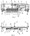
- Figure 2 shows a view of the apparatus according to the invention in direction A marked in Fig. 1;
- Figure 3 shows a view of the apparatus according to the invention in direction B marked in Fig. 1;
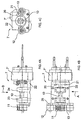
- Figures 4A-4C show a drilling module in the apparatus according to the invention;
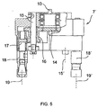
- Figure 5 shows a partially sectional view of a multispindle drilling module in the apparatus according to the invention; and
- Figures 6A - 6C show schematically the position control arrangement of drills for one drilling module as seen from the direction of the cylinder being machined.
- The method according to the invention concerns a technique for drilling holes in the shell of a paper machine cylinder s2, with the cylinder being unremoved from its operating position in the paper machine, whereby the drilling apparatus 1 is fixed to the adjacent cylinder s1. In the method the disturbing influence of mechanical play in the structures of said adjacent cylinder s1 is eliminated prior to drilling. The mechanical play is eliminated by applying such a
support member 29 on said adjacent cylinder s1 that can exert tangential forces on said cylinder. On the cylinder s2 being machined is applied at least onesupport member 29 which is a part of the drilling apparatus 1. Thus, thesupport member 29 also eliminates unwanted movement of the cylinder s2 being machined. - The apparatus according to the invention concerns equipment for drilling holes in the shell of a paper machine cylinder s2, said apparatus comprising a
framework 2 with a construction supportable on the structures of the paper machine and afeed frame 6 which, supported by theframework 2, is adapted to be movable toward the surface of the cylinder to be machined, said feed frame comprising a plurality of drilling modules adapted to be driven by means of a drive unit. For drilling, the apparatus is fixed to the adjacent cylinder s1 and the drilling apparatus includes means for eliminating the disturbing influence of mechanical play in the structures of said adjacent cylinder s1. For this purpose, the drilling apparatus includessupport members 29 capable of exerting tangential forces on said adjacent cylinder s1. Saidsupport members 29 are pneumatic cylinders adapted into theframework 2 of the drilling apparatus and are in their operating positions driven tight against the cylinder s2 to be machined. - With reference to Fig. 1, therein is shown a preferred embodiment of the apparatus 1 according to the invention in its operating position supported on the structures of a paper machine such as a first cylinder s1 of the paper machine. The cylinder s2 to be drilled is situated laterally offset below the first cylinder s1. The apparatus 1 includes a
framework 2 with a construction supportable on the structures of the paper machine. Theframework 2 is supported on the first cylinder s1 by means ofsupport members 3, 4 such as curved plates 4 resting on the shell of the cylinder. The curved plates are further connected to theframework 2. Advantageously, the apparatus is anchored by means of fasteningbelts 5 to the surface of the first cylinder s1. Thus, theframework 2 will be aligned essentially parallel to the axis of the cylinder s1 at least over a portion of the cylinder width. - The apparatus 1 includes a
feed frame 6 which, supported by theframework 2, is adapted to be movable toward the surface of the cylinder s2 being machined, said feed frame comprising a plurality ofdrilling modules 7 adapted to be driven by means of adrive unit 8. On theframework 2 are adaptedguideways 9 along which thefeed frame 6 can be moved in order to provide the feed movement of thedrilling modules 7 as well as the withdrawal movement thereof outward from the cylinder surface after the completion of the drilling step. Thedrilling modules 7 include at least two spindle heads. The embodiment illustrated in Fig. 2 has six two-spindle drilling modules 7 adapted for simultaneous drive by means of adrive unit 8. - Each
drilling module 7 has a central drive shaft which in the embodiment illustrated in the diagrams is belt-driven. The belt drive train is accomplished by providing thedrive shaft 10 with abelt drive pulley 11 and thedrilling module 7 withbelt idler pulleys drive shaft 10, so as to rotate therewith, is mounted a first gear wheel 14 (cf. Fig. 5), which is adapted to drive agear transmission 16 of anintermediate shaft 15 that further drives aspindle shaft 17. In the embodiment illustrated in the diagrams, eachdrilling module 7 includes twospindle heads 18, 18', driven in the above-described manner by thedrive shaft 10 of the drilling module. At least onespindle head 18, 18' in each drilling module is arranged rotatable about theintermediate shaft 15, 15' of the drilling module. Thus, the mutual distance of the spindle shaft centers 19, 19' from each other can be adjusted in each drilling module separately by means of rotating at least onespindle head 18, 18' in the drilling module about theintermediate shaft 15, 15' of the drilling module. Furthermore, the entire drilling module, or at least the spindle head housing the spindle shafts is arranged rotatable about thedrive shaft 10, thus making it possible to control the drilling pattern produced by eachdrilling module 7. Resultingly, the spindle shaft centers 19, 19' of a two-spindle drilling module can be readily aligned on a desired line. - Each
drilling module 7 has means 20, 21 for locking the drilling module into a desired position. Thedrilling module 7 includes a mounting plate 22 (cf. Fig. 4) of the spindle head 7', said mounting plate having arranged thereon thebearing assemblies 23, 24 of thedrive shaft 10 as well assupport elements 25 for mounting the belt idler pulleys 12, 13. The spindlehead mounting plate 11 is provided with holes, slots orsimilar openings 26 for fixing the spindle head into a desired position by means offasteners drilling modules 7 are mounted by their mountingplates 22 in a movable manner on aguideway 33 adapted on thefeed frame 6. Resultingly, a still further facility of controlling the layout of the drilling pattern can be obtained by altering the position of thedrilling modules 7 in thefeed frame 6. In Fig. 2, such a position control possibility is indicated by arrows. - In Figs. 2 and 3 is shown schematically a drilling apparatus 1 according to the invention. The drilling apparatus is built on a
framework 2. Theframework 2 includes a mountingmember 3 to which the curved backing plates 4 are connected. The framework consists of abody 2 including guideways for the movement of thefeed frame 6, and anactuator assembly feed frame 6 with respect to thedrilling apparatus body 2. The actuator of thefeed frame 6 comprises a conventional screw lift (jack) 27, driven by means of adrive motor 28. Into thefeed frame 6 are adapted a number ofparallel drilling modules 7, all driven by means of acommon drive unit 8. The drive unit is mounted on the feed frame. - The framework, advantageously the
body 2 thereof, is provided withsupport members 29, advantageously comprising pneumatic cylinders, which, prior to the machining operation, are driven against the surface of the cylinder s2 to be machined, whereby any possible play, that is, the instability in the bearings of the cylinder s1 and the support structures thereof acting as the mounting base of the drilling apparatus is minimized and the drilling operation itself becomes very stable. This arrangement prevents, for instance, unwanted movements of the drilling apparatus during the drilling operation, whereby the breaking of thedrills 30 is eliminated. - The drilling operation takes place as follows. The drilling apparatus is first mounted on the cylinder s1 next closest to the cylinder s2 to be machined by means of fastening belts. The spindle heads of the
drilling modules 7 are next adjusted into a desired position and the spindle head 7' of the drilling module is rotated with respect to thedrive shaft 10 if so needed. Furthermore, the mutual distances between thedrilling modules 7 are set as required to obtain the desired drilling pattern. Thesupport members 29 are driven against the surface of the cylinder s2 to be machined. With the help of theactuator assembly feed frame 6 is moved toward the cylinder to be machined. Finally, therotary drive unit 8 of the spindle heads 30 is switched on. After the completion of the drilling step, these actions are repeated in a reverse order. - The cylinder s2 being machined is rotated between the drilling steps by means of a rotary drive system (not shown in the diagrams) about the cylinder shaft incrementally by a given angle into the next drilling position. One type of such a rotary drive system is described in patent publication EP-B-0448947. However, such a rotary drive system can rotate the cylinder only by increments determined by the pitch of the gear wheel mounted in the drive unit. Hence, each different size of incremental angle of rotation would need a separate gear wheel. To overcome this limitation, a conventional indexing wheel can be used to convert the increment angle of rotation into a suitable value. The cylinder being machined is locked into a fixed position for the duration of the machining step.
- In Fig. 3 the rotational drive of the drilling modules is partially visible. The drive means 8, which advantageously is a conventional electric motor, transmits its power feed from the
motor output shaft 31 via abelt transmission train 32 to thedrive shafts 10 of thedrilling modules 7, wherefrom the power feed is distributed individually to each of the spindle heads carrying thedrills 30. - In Figs. 4A-4C is shown one of the drilling modules and in Fig. 5 one spindle head 7' of the drilling module. The spindle shaft centers 19, 19' are made rotatably adjustable about each of the
intermediate shafts 15, 15', the number of which in the embodiment illustrated in the diagram is two. - The position control of the drilling module is illustrated in schematic manner in Figs. 6A, 6B and 6C. In Fig. 6A the mutual distance between the spindle shaft centers 19, 19' of the two-spindle head 7' is shown driven into the maximally outdistanced position. However, the spindle head 7' of the drilling module has not been rotated about the
drive shaft 10. In Fig. 6B both spindle shaft centers 19, 19' are shown rotated about theintermediate shaft 15, 15'. Then the mutual distance between the spindle shaft centers 19, 19' becomes smaller than in Fig. 6A, and additionally, the drills are offset at a distance from the centerline of drilling. When required, the drilling pattern may further be controlled by rotating the frame of the spindle head 7' about thecenter axis 10, whereby it is possible to bring the spindle shaft centers 19, 19' to the centerline of drilling, for instance. - To those versed in the art it is obvious that the invention is not limited by the embodiments described above, but rather, can be varied within the spirit and scope of the appended claims.
Claims (6)
- A method for drilling holes in the shell of a paper machine cylinder (s2), with said cylinder being unremoved from its operating position in a paper machine, in which method a drilling apparatus (1) is fixed to the adjacent cylinder (s1), characterized in that the influence of mechanical play in the structures of said adjacent cylinder (s1) is eliminated prior to drilling.
- A method as defined in claim 1, characterized in that the mechanical play is eliminated by applying such a support member (29) on said adjacent cylinder (s1) that can exert tangential forces on said cylinder.
- A method as defined in claim 1 or 2, characterized in that on the cylinder (s2) being machined is applied at least one support member (29) which is a part of the drilling apparatus (1).
- An apparatus for drilling holes in the shell of paper machine cylinder (s2), said apparatus comprising a stationary framework adapted supportable on the structures of the paper machine and a feed frame adapted movable along said stationary framework radially toward the shell of said cylinder, said feed frame carrying a plurality of drilling modules adapted rotatable by means of a drive unit, wherein the apparatus is fixable to the adjacent cylinder (s1) characterized in that the drilling apparatus includes means for eliminating the influence of mechanical play in the structures of said adjacent cylinder (s1).
- An apparatus as defined in claim 4, characterized in that the drilling apparatus includes support members (29) capable of exerting tangential forces on said adjacent cylinder (s1).
- An apparatus as defined in claim 4 or 5, characterized in that said support members (29) are pneumatic cylinders adapted into the framework (2) of the apparatus and are in their operating positions driven against the cylinder (s2) to be machined.
Applications Claiming Priority (2)
| Application Number | Priority Date | Filing Date | Title |
|---|---|---|---|
| FI981599 | 1998-07-13 | ||
| FI981599A FI109885B (en) | 1998-07-13 | 1998-07-13 | Method and apparatus for drilling holes in the casing of a cylinder |
Publications (3)
| Publication Number | Publication Date |
|---|---|
| EP0972598A2 EP0972598A2 (en) | 2000-01-19 |
| EP0972598A3 EP0972598A3 (en) | 2003-05-21 |
| EP0972598B1 true EP0972598B1 (en) | 2006-01-04 |
Family
ID=8552185
Family Applications (1)
| Application Number | Title | Priority Date | Filing Date |
|---|---|---|---|
| EP99202186A Expired - Lifetime EP0972598B1 (en) | 1998-07-13 | 1999-07-06 | Method and apparatus for drilling holes in the shell of a cylinder |
Country Status (5)
| Country | Link |
|---|---|
| US (1) | US6789984B1 (en) |
| EP (1) | EP0972598B1 (en) |
| CA (1) | CA2273299C (en) |
| DE (1) | DE69929275T2 (en) |
| FI (1) | FI109885B (en) |
Families Citing this family (2)
| Publication number | Priority date | Publication date | Assignee | Title |
|---|---|---|---|---|
| JP4543306B2 (en) * | 2003-10-07 | 2010-09-15 | 内山工業株式会社 | Encoder with cylindrical cover |
| US20120175366A1 (en) * | 2011-01-10 | 2012-07-12 | GM Global Technology Operations LLC | Vent hole alignment of temperature-pressure relief devices on pressure vessels |
Family Cites Families (11)
| Publication number | Priority date | Publication date | Assignee | Title |
|---|---|---|---|---|
| US780799A (en) * | 1903-08-07 | 1905-01-24 | Simon J Kabaker | Drill. |
| US1399073A (en) * | 1919-07-29 | 1921-12-06 | Heine Safety Boiler Company | Reaming-machine |
| US1854053A (en) * | 1926-10-15 | 1932-04-12 | Paper & Textile Machinery Co | Method and machine for perforating suction-roll shells |
| US1884752A (en) * | 1929-08-05 | 1932-10-25 | Ex Cello O Aircraft And Tool C | Multiple drill head |
| US2506202A (en) * | 1948-08-13 | 1950-05-02 | Sr Harold E Folkerth | Multiple close centered gear head |
| US4674925A (en) * | 1986-10-03 | 1987-06-23 | Ashcombe Products Company | Gang drill and method for clearing patterns of holes in tubular members |
| US5401232A (en) * | 1989-01-09 | 1995-03-28 | Valmet Paper Machinery, Inc. | Rolls and cylinders for use in paper machines |
| FI81892C (en) * | 1989-01-09 | 1990-12-10 | Valmet Paper Machinery Inc | FOERFARANDE FOER TILLVERKNING AV VALSAR ELLER CYLINDRAR FOER PAPPERSMASKIN SAMT MED FOERFARANDET TILLVERKAD VALS ELLER CYLINDER. |
| FI91135C (en) | 1990-03-19 | 1994-05-25 | Valmet Paper Machinery Inc | A method of drilling holes in the cylinder liner of a paper machine and the equipment used in the method |
| FI91834C (en) * | 1991-11-29 | 1994-08-25 | Valmet Paper Machinery Inc | Plant for drilling holes in the casing of a cylinder in a paper machine |
| FI110313B (en) | 1997-04-03 | 2002-12-31 | Metso Paper Inc | Method and apparatus for drilling holes in a cylinder for a paper machine or equivalent sheath |
-
1998
- 1998-07-13 FI FI981599A patent/FI109885B/en not_active IP Right Cessation
-
1999
- 1999-05-28 CA CA002273299A patent/CA2273299C/en not_active Expired - Fee Related
- 1999-07-06 DE DE69929275T patent/DE69929275T2/en not_active Expired - Lifetime
- 1999-07-06 EP EP99202186A patent/EP0972598B1/en not_active Expired - Lifetime
- 1999-07-12 US US09/351,166 patent/US6789984B1/en not_active Expired - Fee Related
Also Published As
| Publication number | Publication date |
|---|---|
| CA2273299A1 (en) | 2000-01-13 |
| FI981599A0 (en) | 1998-07-13 |
| DE69929275T2 (en) | 2006-08-31 |
| DE69929275D1 (en) | 2006-03-30 |
| FI981599L (en) | 2000-01-14 |
| FI109885B (en) | 2002-10-31 |
| CA2273299C (en) | 2007-01-02 |
| US6789984B1 (en) | 2004-09-14 |
| EP0972598A3 (en) | 2003-05-21 |
| EP0972598A2 (en) | 2000-01-19 |
Similar Documents
| Publication | Publication Date | Title |
|---|---|---|
| DE69332986T2 (en) | Grinding machine with multiple, parallel, grinding belts for simultaneous grinding of surfaces of a workpiece | |
| EP1207028B1 (en) | Drilling machine for panels | |
| US5090846A (en) | Method and apparatus for drilling of holes into the mantle of a cylinder | |
| EP0980732B1 (en) | Method and apparatus for drilling holes in the shell of a cylinder | |
| CA2083997C (en) | Method and device for drilling of holes into a mantle of a cylinder in a paper machine | |
| CA2273299C (en) | Method and apparatus for drilling holes in the shell of a cylinder | |
| EP0239398B1 (en) | Cutting machine for decorative chains | |
| EP0426234B1 (en) | Apparatus and method for the in-line cropping and/or chamfering of a plastic tube | |
| US5927909A (en) | Method and device for drilling holes into a mantle of a cylinder of a paper machine | |
| US6264405B1 (en) | Method and device for drilling holes into the mantle of a cylinder or equivalent of a paper machine | |
| CN216096486U (en) | Multi-shaft drilling device | |
| US6401783B1 (en) | Two drum turret for tire building | |
| JPH07276117A (en) | Spindle drive device of multiple spindle drilling machine | |
| DE69221720T2 (en) | DEVICE FOR DRIVING A TURNING TOOL | |
| FI86899C (en) | Method for repairing the locking surface of a spacer and device in accordance with the method | |
| FI84890C (en) | FOERFARANDE FOER ISTAONDSAETTNING AV VALSYTAN AV EN VALS I EN PAPPERSMASKIN OCH ANORDNING FOER ISTAONDSAETTNING AV EN VALSYAN. | |
| JPH0957501A (en) | Internal cutting method for cylindrical member, internal cutting device, and roll | |
| SE8704014D0 (en) | PAPER COLLECTION MACHINE CONTROL |
Legal Events
| Date | Code | Title | Description |
|---|---|---|---|
| PUAI | Public reference made under article 153(3) epc to a published international application that has entered the european phase |
Free format text: ORIGINAL CODE: 0009012 |
|
| AK | Designated contracting states |
Kind code of ref document: A2 Designated state(s): AT BE CH CY DE DK ES FI FR GB GR IE IT LI LU MC NL PT SE |
|
| AX | Request for extension of the european patent |
Free format text: AL;LT;LV;MK;RO;SI |
|
| RAP1 | Party data changed (applicant data changed or rights of an application transferred) |
Owner name: VOITH PAPER PATENT GMBH Owner name: PIKOTEKNIK OY |
|
| PUAL | Search report despatched |
Free format text: ORIGINAL CODE: 0009013 |
|
| AK | Designated contracting states |
Designated state(s): AT BE CH CY DE DK ES FI FR GB GR IE IT LI LU MC NL PT SE |
|
| AX | Request for extension of the european patent |
Extension state: AL LT LV MK RO SI |
|
| 17P | Request for examination filed |
Effective date: 20030909 |
|
| AKX | Designation fees paid |
Designated state(s): DE FI GB IT SE |
|
| 17Q | First examination report despatched |
Effective date: 20040526 |
|
| GRAP | Despatch of communication of intention to grant a patent |
Free format text: ORIGINAL CODE: EPIDOSNIGR1 |
|
| GRAS | Grant fee paid |
Free format text: ORIGINAL CODE: EPIDOSNIGR3 |
|
| GRAA | (expected) grant |
Free format text: ORIGINAL CODE: 0009210 |
|
| AK | Designated contracting states |
Kind code of ref document: B1 Designated state(s): DE FI GB IT SE |
|
| REG | Reference to a national code |
Ref country code: GB Ref legal event code: FG4D |
|
| REG | Reference to a national code |
Ref country code: SE Ref legal event code: TRGR |
|
| REF | Corresponds to: |
Ref document number: 69929275 Country of ref document: DE Date of ref document: 20060330 Kind code of ref document: P |
|
| RAP2 | Party data changed (patent owner data changed or rights of a patent transferred) |
Owner name: VOITH PATENT GMBH Owner name: PIKOTEKNIK OY |
|
| PLBE | No opposition filed within time limit |
Free format text: ORIGINAL CODE: 0009261 |
|
| STAA | Information on the status of an ep patent application or granted ep patent |
Free format text: STATUS: NO OPPOSITION FILED WITHIN TIME LIMIT |
|
| 26N | No opposition filed |
Effective date: 20061005 |
|
| PGFP | Annual fee paid to national office [announced via postgrant information from national office to epo] |
Ref country code: SE Payment date: 20110722 Year of fee payment: 13 Ref country code: GB Payment date: 20110721 Year of fee payment: 13 |
|
| PGFP | Annual fee paid to national office [announced via postgrant information from national office to epo] |
Ref country code: IT Payment date: 20110722 Year of fee payment: 13 |
|
| PGFP | Annual fee paid to national office [announced via postgrant information from national office to epo] |
Ref country code: FI Payment date: 20120704 Year of fee payment: 14 |
|
| PGFP | Annual fee paid to national office [announced via postgrant information from national office to epo] |
Ref country code: DE Payment date: 20120720 Year of fee payment: 14 |
|
| REG | Reference to a national code |
Ref country code: SE Ref legal event code: EUG |
|
| GBPC | Gb: european patent ceased through non-payment of renewal fee |
Effective date: 20120706 |
|
| PG25 | Lapsed in a contracting state [announced via postgrant information from national office to epo] |
Ref country code: GB Free format text: LAPSE BECAUSE OF NON-PAYMENT OF DUE FEES Effective date: 20120706 Ref country code: SE Free format text: LAPSE BECAUSE OF NON-PAYMENT OF DUE FEES Effective date: 20120707 |
|
| PG25 | Lapsed in a contracting state [announced via postgrant information from national office to epo] |
Ref country code: IT Free format text: LAPSE BECAUSE OF NON-PAYMENT OF DUE FEES Effective date: 20120706 |
|
| PG25 | Lapsed in a contracting state [announced via postgrant information from national office to epo] |
Ref country code: FI Free format text: LAPSE BECAUSE OF NON-PAYMENT OF DUE FEES Effective date: 20130706 Ref country code: DE Free format text: LAPSE BECAUSE OF NON-PAYMENT OF DUE FEES Effective date: 20140201 |
|
| REG | Reference to a national code |
Ref country code: DE Ref legal event code: R119 Ref document number: 69929275 Country of ref document: DE Effective date: 20140201 |