US1854053A - Method and machine for perforating suction-roll shells - Google Patents
Method and machine for perforating suction-roll shells Download PDFInfo
- Publication number
- US1854053A US1854053A US141750A US14175026A US1854053A US 1854053 A US1854053 A US 1854053A US 141750 A US141750 A US 141750A US 14175026 A US14175026 A US 14175026A US 1854053 A US1854053 A US 1854053A
- Authority
- US
- United States
- Prior art keywords
- shell
- drills
- perforations
- drilling
- successive
- Prior art date
- Legal status (The legal status is an assumption and is not a legal conclusion. Google has not performed a legal analysis and makes no representation as to the accuracy of the status listed.)
- Expired - Lifetime
Links
- 238000000034 method Methods 0.000 title description 11
- 238000005553 drilling Methods 0.000 description 59
- 230000033001 locomotion Effects 0.000 description 57
- 238000006073 displacement reaction Methods 0.000 description 13
- 230000000694 effects Effects 0.000 description 3
- 230000000737 periodic effect Effects 0.000 description 3
- 239000012634 fragment Substances 0.000 description 2
- 238000000227 grinding Methods 0.000 description 2
- 238000003754 machining Methods 0.000 description 2
- 238000012856 packing Methods 0.000 description 2
- 238000004519 manufacturing process Methods 0.000 description 1
- 239000002184 metal Substances 0.000 description 1
- 238000005498 polishing Methods 0.000 description 1
- 125000006850 spacer group Chemical group 0.000 description 1
- 239000004753 textile Substances 0.000 description 1
- 238000009827 uniform distribution Methods 0.000 description 1
- 238000004804 winding Methods 0.000 description 1
Images
Classifications
-
- B—PERFORMING OPERATIONS; TRANSPORTING
- B23—MACHINE TOOLS; METAL-WORKING NOT OTHERWISE PROVIDED FOR
- B23B—TURNING; BORING
- B23B39/00—General-purpose boring or drilling machines or devices; Sets of boring and/or drilling machines
- B23B39/16—Drilling machines with a plurality of working-spindles; Drilling automatons
- B23B39/161—Drilling machines with a plurality of working-spindles; Drilling automatons with parallel work spindles
-
- B—PERFORMING OPERATIONS; TRANSPORTING
- B23—MACHINE TOOLS; METAL-WORKING NOT OTHERWISE PROVIDED FOR
- B23B—TURNING; BORING
- B23B35/00—Methods for boring or drilling, or for working essentially requiring the use of boring or drilling machines; Use of auxiliary equipment in connection with such methods
-
- B—PERFORMING OPERATIONS; TRANSPORTING
- B23—MACHINE TOOLS; METAL-WORKING NOT OTHERWISE PROVIDED FOR
- B23Q—DETAILS, COMPONENTS, OR ACCESSORIES FOR MACHINE TOOLS, e.g. ARRANGEMENTS FOR COPYING OR CONTROLLING; MACHINE TOOLS IN GENERAL CHARACTERISED BY THE CONSTRUCTION OF PARTICULAR DETAILS OR COMPONENTS; COMBINATIONS OR ASSOCIATIONS OF METAL-WORKING MACHINES, NOT DIRECTED TO A PARTICULAR RESULT
- B23Q1/00—Members which are comprised in the general build-up of a form of machine, particularly relatively large fixed members
- B23Q1/25—Movable or adjustable work or tool supports
- B23Q1/44—Movable or adjustable work or tool supports using particular mechanisms
- B23Q1/48—Movable or adjustable work or tool supports using particular mechanisms with sliding pairs and rotating pairs
- B23Q1/4828—Movable or adjustable work or tool supports using particular mechanisms with sliding pairs and rotating pairs a single rotating pair followed parallelly by a single sliding pair
-
- D—TEXTILES; PAPER
- D21—PAPER-MAKING; PRODUCTION OF CELLULOSE
- D21F—PAPER-MAKING MACHINES; METHODS OF PRODUCING PAPER THEREON
- D21F3/00—Press section of machines for making continuous webs of paper
- D21F3/02—Wet presses
- D21F3/10—Suction rolls, e.g. couch rolls
- D21F3/105—Covers thereof
-
- Y—GENERAL TAGGING OF NEW TECHNOLOGICAL DEVELOPMENTS; GENERAL TAGGING OF CROSS-SECTIONAL TECHNOLOGIES SPANNING OVER SEVERAL SECTIONS OF THE IPC; TECHNICAL SUBJECTS COVERED BY FORMER USPC CROSS-REFERENCE ART COLLECTIONS [XRACs] AND DIGESTS
- Y10—TECHNICAL SUBJECTS COVERED BY FORMER USPC
- Y10T—TECHNICAL SUBJECTS COVERED BY FORMER US CLASSIFICATION
- Y10T408/00—Cutting by use of rotating axially moving tool
- Y10T408/03—Processes
-
- Y—GENERAL TAGGING OF NEW TECHNOLOGICAL DEVELOPMENTS; GENERAL TAGGING OF CROSS-SECTIONAL TECHNOLOGIES SPANNING OVER SEVERAL SECTIONS OF THE IPC; TECHNICAL SUBJECTS COVERED BY FORMER USPC CROSS-REFERENCE ART COLLECTIONS [XRACs] AND DIGESTS
- Y10—TECHNICAL SUBJECTS COVERED BY FORMER USPC
- Y10T—TECHNICAL SUBJECTS COVERED BY FORMER US CLASSIFICATION
- Y10T408/00—Cutting by use of rotating axially moving tool
- Y10T408/36—Machine including plural tools
- Y10T408/38—Plural, simultaneously operational tools
- Y10T408/3844—Plural, simultaneously operational tools with tool-opposing, work-engaging surface
-
- Y—GENERAL TAGGING OF NEW TECHNOLOGICAL DEVELOPMENTS; GENERAL TAGGING OF CROSS-SECTIONAL TECHNOLOGIES SPANNING OVER SEVERAL SECTIONS OF THE IPC; TECHNICAL SUBJECTS COVERED BY FORMER USPC CROSS-REFERENCE ART COLLECTIONS [XRACs] AND DIGESTS
- Y10—TECHNICAL SUBJECTS COVERED BY FORMER USPC
- Y10T—TECHNICAL SUBJECTS COVERED BY FORMER US CLASSIFICATION
- Y10T408/00—Cutting by use of rotating axially moving tool
- Y10T408/55—Cutting by use of rotating axially moving tool with work-engaging structure other than Tool or tool-support
- Y10T408/561—Having tool-opposing, work-engaging surface
- Y10T408/5614—Angularly adjustable surface
Definitions
- Thisinvention pertains to the manufacture of suction-roll shells, and aims to provide an improved method and machine for drilling the shell perforations.
- Fig. 1 is a longitudinal section of the illustrative machine.
- Fig. 2 is a sectional end elevation taken on the line 2-2 of Fig. 1, looking in the direction of the arrows.
- Figs. '3 and 4 are details of different screwthreads which may be used on an element of 1 the machine.
- Fig. 5 is a detail of a registration device.
- Fig. 6 represents an elevation of a suctionroll shell made or being made in accordance with the invention, and showing some of its perforations.
- Fig. 7 represents on an enlarged scale a fragment of a completed shell, showing a preferred form and arrangement of perforations.
- Fig. 8 represents a fragment of another such shell with perforations of somewhat different size and spacing from those shown in the preceding figures.
- Fig. 1 the cylindric metal shell A to be drilled is shown mounted in the machine in operative relation to mechanism for drilling the perforations in the shell.
- the drilling mechanism is represented by a gang of rotary drills 10.
- the supporting means for these drills, and the operating means by which the drills are caused to advance against and drill through the wall of the shell and then to reverse and withdraw therefrom, may be of any known or approved type. Such mechanism, being well understood in the art, is not herein specifically illustrated.
- the drills operate successively on successively exposed parts of the shell.
- the illustrative machine embodies means whereby the successive relative positioning of the shell and drills for the successive drilling operations are so determined that the perforations are drilled in circumferentially extending lines oblique to a plane perpendicular to the shell axis, and more specifically according to a tion between the shell and drills.
- the positioning action involves successively changing the angular relationship of the shell and drills, with accompanying relative movements in a longitudinal direc- In the illustrative machine these movements are so governed from position determining mechanism that any individual drill, as well as thewhole gang of drills, operates around the cylinder in a spiral course.
- the line XY indicates a plane perpendicular to the axis of the shell A.
- the line XZ indicates a spiral accord- 1 ing to which the shell perforations are disposed.
- the successive relative positioning of the shell A and drills 10 is therein ob tamed by combined rotative and longitudinal movements of the shell itself, the drills being mounted in a fixed support or carriage (not shown).
- the drills are represented as arranged above the shell, though in practice they would preferably be arranged at the side of the shell for clearance of chips.
- the shell A is shown supported by heads 11 and 12, which are clamped to the ends of the shell by clamp members 13 and wedge rings 14. Bolts connecting the clamp members and heads are shown as long rods 15- extending through the hollow shafts carrying the heads.
- Said shafts, respectively des- 10C ignated 16 and 17, are in axial alignment and are slidable as well as rotatable in their respective bearings 18 and 19.
- the shaft 17 carrying the head 12 is connected with mechanism for successively imparting screw movements to said shaft for successively positioning the shell A'in relation to the drills. These movements are communicated through the shell .to the opposite head 11 which is floating or free to respond to the shell movements.
- Thehead 11 may also be shifted toward or away from the head 12 to permit mounting the shell in the machine or its removal therefrom.
- a crank 20 is shown on the shaft of a pinion 21, which meshes with a gear 22 on the shaft of a worm 23, which drives the worm wheel 24 on said shaft 17.
- the shaft 17 slides in the worm wheel hub 25 which has keys engaging longitudinal keyways 26 in said shaft.
- a spacer .27 between the bearing 19 and the worm wheel hub prevents longitudinal displacement of the worm wheel.
- the screw portion 30 of the shaft 17 is engaged by a stationary nut 31, whereby the shaft is moved longitudinally as it is rotated.
- Said nut 31 is shown as an internally threaded bushing secured in the bearing 29 by diametrically opposite fastenings 32.
- the shaft 17 is operated through reduction gearing so that one complete revolution of the crank 20 will turn the shell A through only a small angle.
- the shell is moved longitudinally a correspondingly small fraction of the distance between successive threads of the screw 30.
- crank 20 is held in a definite fixed position, as indicated in Fig. 2, thereby locking the operating means and holding the shell stationary.
- crank handle 35 is carried on the shank of a spring pressed plunger 36 which normally engages a so-called index notch 37 in the machine frame.
- the plunger is disengaged from said index notch, and the crank is turned one complete revolution, allowing the plunger to snap back into the index notch.
- the shell is thereby accurately positioned and held for the ensuing drilling operation.
- the gearing between the crank 20 and shaft 17 determines the spacing between the centers of successive perforations around the shell; and the pitch of the screw 30 dedetermines the spiral course of the successively drilled longitudinal rows of perforations.
- the pitch of the screw 30 may of course vary in different machines.
- Fig. 3 indicates the thread of a screw for governing the drilling according to the spiral adopted in Fig. 7; while Fig. 4 indicates the thread of a screw for governing the irilling according to the spiral adopted in Fig.
- the shell A will have been turned one half the distance between centers of adjacent longitudinal rows of perforations.
- the nut 31 is then unfastened and given a half turn in a direction to reverse the screw 30 and is then refastened in place.
- This manipulation will have moved the shell longitudinally half the distance between successive threads of the screw 30, i. e. half the distance between centers of adjacent perforations in the same longitudinal row.
- the shell is accordingly positioned so that the first or index drill 10 will drill the hole I; (Fig. 7).
- the second series of perforations may then .be drilled in the same manner and with the same effect as the first, resulting in the product shown in Fig. 7.
- FIG. 5 shows a so-called indexing pin 40 inserted through a bushing in the shell supporting head 12 and into a hole 41 preliminarily drilled in the end of the shell A. This registers a determined point on the shell, e., g. the hole 41, with a determined point on the machine, e. g. the pin 40.
- the shell perforating operation be initiated with the shell and head 12 thus related, and with the screw shaft 17 at a predetermined position, for instance its extreme retracted position, then after completion of the operation and removal of the shell it may be remounted in the machine in the same predetermined situation or relation to the machine parts, so that the first or index perforation a will have its center in exact registration with the center of the first or index drill 10; and thus all the perforations may be redrilled or further operated upon with the same or other drills by the procedure before explained.
- the shell drilled in the manner described has its perforations in general centered on different transverse planes perpendicular to the shell axis. Obviously no two perforations on the same spiral line can lie in the same such plane. And by adopting a spiral of small pitch the said planes of the centers of the perforations will be closely adjacent.
- the shell perforations will traverse the machining and grinding tools or the suction-box packings, as the case may be, at successively longitudinally ofi'set points, avoiding concentration of tools and obtaining a substantially uniform distribution of wear between the shell and box packings inthe completed suction-roll.
- the perforating operation may-also bevery -wear at particular points on the finishing conveniently and accurately practiced, and
- the word periodic as applied to the drill spacing is exemplified in the illustrative machine by the uniform drill spacing, and is to be understood as signifying that the drills are spaced uniformly apart or else in uniformly sp acedgroups with the spacing between groups a multiple of the distance between adjacent drills.
- a method of drilling a cylindric shell involving the drilling of a series of perforations arranged in a continuous spiral of a plurality of convolutions, characterized by successively subjecting the shell to the operation of a plurality of drills arranged in a longitudinal row and uniformly spaced to drill holes centered on different convolutions of said spiral, and, in alternation with the drilling operations, successively shifting the relative positions of the shell and drills by relative displacements through aliquot fractions of a revolution and through aliquot fractions of a total axial displacement equal to the pitch of the spiral.
- a shell drilling method characterized by successively operating on the shell with a longitudinally disposed series of periodically spaced drills and successively relatively positioning the shell and drills for successive drilling operations by successive equal increments of relative rotative and axial movements so related to the drill spacing that a given number of positionings will bring the drills within the range of the area to be perforated into registry each with a hole previously drilled by another of said drills, where'- by the said series of drills will have completed the drilling of a series of equally spaced perforations arranged according to the course of a continuous spiral of a plurality of convolutions about the shell, the said axial movements being aliquot fractions of the distance between adjacent drill centers.
- a machine-for drilling a cylindric shell having, in combination, a gang of uniformly spaced drills arranged in a longitudinal row; means for holding the shell in operative relation to said drills; and means for successively shifting the relative positions of the shell and drills, between successive drilling operations, by relative rotative movements through aliquot fractions of a revolution and relative axial displacements which are aliquot fractions of the distance betweendrill row; means for successively relatively positioning the shell and drills for successive drilling operations by relative rotative and longitudinal movement so related to the drill spacing that the successively drilled holes are disposed according to the course of a continuous spiral of small pitch having a plurality of closely adjacent convolutions; and re-setting means whereby the machine may be organized to repeat its operations to drill a second like spiral series of holes in staggered relation to the first series.
- a machine of the class described comprising, in combination, shell supporting means; a gang of drills disposed longitudinally of the shell for successively drilling pluralities of holes therein; means for effecting relative rotation between the shell and drills in successive equal stages of partial rotative movement; means for effecting relative longitudinal movement between the shell and drills in successive slight equal stages of such movement; the shell and drills being successively related for successive drilling operations by the successive relative rotative and longitudinal movements and the drills being so spaced in relation to the successive movements that the positioning movement after a given number of operations will bring the drills within the range of the perforated area into registry each with a hole previously drilled by another of the drills, whereby the holes drilled by the gang of drills in a given succession of operations will be disposed according to the course of a continuous spiral having a plurality of convolutions.
- a machine of the class described comprising, in combination, shell supporting means; a gang of drills disposed longitudinally of the shell for successively drilling pluralities of holes therein; means for effecting relative rotationb-etween the shell and drills in successive equal stages of partial rotative movement; means for effecting relative longitudinal movement between the shell and drills in successive slight equal stages of such movement; the shell and drills being successively related for successive T drilling operations by the successive relative rotative and longitudinal movements; and the drills being so spaced in relation to the successive movements that the holes drilled by the gang of drills in a given succession of operations will be.disposed according to the course of a continuous spiral having a drills whereby it may be re-set for drilling a second like series of holes with the same drills, the aforesaid means for elfecting relative rotative and longitudinal movements in stages being likewise operable when the machine is re-set.
- a machine of the class described comprising, in combination, shell supporting means; a gang of drills disposed longitudinally of the shell for successively drilling pluralities of holes therein; means for effecting relative rotation between the shell and drills in successive equal stages of partial rotative movement; means for effecting relative longitudinal movement between the shell and drills in successive slight equal stagesof such movement; the shell and drills being successively related for successive drilling operations by the successive relative rotative and longitudinal movements; and the drills being so spaced in relation to the successive movements that the holes drilled by the gang of drills in a given succession of operations will be disposed according to the course of a continuous spiral having a plurality of convolutions; the machine embodying means operable to effect a relative shift between the shell and drills through a relative rotary movement of one-half the amount of one of I the machine being organized and arranged so that the successive motions of the screw.
- a machine of the class described comprising, in combination, a gang of drills disposed longitudinally for successively drilling pluralities of holes in the shell; shell supportmg means comprising rotatable shell-clamping heads mounted to permit movement of the heads and shell in an axial direction; a screw connected with one of said heads; means for successively operating said screw by equal partial step-by-step rotative movements.
- a machine for drilling a cylindric shell having, in combination, a gang of uniformly spaced drills arranged in a longitudinal row; means for holding the shell in operative relation to said drills; and means for successively shifting the relative positions of the shell and drills, between'successive drilling operations, by equal relative rotative movements and equal relative longitudinal displacements, the total longitudinal displacement being equal' to the distance between adjacent drill centers, whereby the holes formed by the drills are disposed on a continuous spiral.
- a machine for drilling perforations in a suction roll shell comprising a longitudinally arranged gang of periodically spaced drills for operating successively on the shell at diflferent relative positions between the shell and drills, and means whereby the successive relative positions of the shell and drills are effected by relative movements both rotatively and longitudinally in successive predetermined stages, the total longitudinal displacement being for a distance which is only a relatively small part of the entire length of the portion of the shell to be drilled, the periodic spacing of the drillsbeinginsuch relation to the movements that after a given succession of operations individual drills will register each with a perforation previously made by another drill; whereby longitudinally extending rows of perforations are successively drilledwith corresponding perforations of the rows disposed on a continuous spiral.
- a method of drilling a cylindric shell involving the drilling of a series of perforations arranged in a continuous spiral of a plurality of convolutions, characterized by successively operating on the shell with a plurality of drills centered todrill holes on difierent convolutions of such spiral, and successively relatively positioning the shell and drills for successive drilling operations by successive increments of relative rotative and longitudinal movements such that after a given succession of operations individual drills will register each with a perforation previously drilled by another drill and the continuous spiral.
- a shell drilling machine embodying a longitudinally arranged series of uniformly spaced drills and mechanism for successively relatively positioning the work and drills for successive drilling operations by equal increments of relative rotative and axial movements so related to the drill spacing that after a given number of operations the said drills will have completed the drilling of a series of holes centered on a continuous spiral of a plurality of convolutions about the shell and the ensuing positioningv movement would bring the drills in the range of the perforated area into registry each with a hole previously drilled by another of the said series of drills, the said axial movements being aliquot fractions of the distance between adjacent drill centers.
- a shell drilling machine embodying a longitudinally arranged series of periodically spaced drills and mechanism for successively relatively positioning the work and drills for successive drilling operations by equal increments of relative rotative and axial movements so related to the drill spacing that the positioning movement following a given number of drilling operations will bring the drills in the range of the perforated area into registry each with a hole previously drilled by another of the series of drills, so that the drills in the said number of operations will have perforated the shell with uniformly spaced perforations disposed according to the course of a continuous spiral of a plurality of convolutions about the shaft, the said axial movements being aliquot fractions of the distance between adjacent drill centers.
- a shell drilling machine embodying a longitudinally arranged series of periodically spaced drills and mechanism for successively relatively positioning the work and drills for successive drilling operations by equal increments of relative rotative and axial movements so related to the drill spacing that the positioning movement following a given number of drilling operations will bring the drills in the range of the perforated area into registry each with a hole previously drilled by another of the series of drills, so that the drills in the said number of operations will have perforated the shell with uniformly spaced perforations disposed according to the course of a continuous spiral of a plurality of convolutions about the shell, and resetting means whereby the machine may be organized to repeat its operations to drill a second like spiral series of holes in staggered relation to the first series, the said axial movements being aliquot fractions of the distance between adjacent drill centers.
- a machine for drilling a cylindric shell having, in combination, a gang of uniformly spaced drills arranged in a longitudinal row; means for holding the shell in operative relation to said drills; and means for successively shifting the relative positions of the shell and drills, between successive drilling operations, by equal relative rotative movements and equal relative longitudinal displacements, the total longitudinal displacements being equal to the distance between adjacent drill centers whereby the successively drilled holes are disposed according to the course of a spiral, the ratio of the pitch of the spiral to the distance between adjacent drill centers being a whole number.
- A. machine for drilling perforations in a suction-roll shell comprising a longitudinally arranged gang of periodically spaced drills for operating successively on the shell at difierent relativepositions betweenthe shell and drills, and means whereby the successive relative positions of the shell and drills are efiected by relative movements both rotatively and longitudinally in successive predetermined stages, the total longitudinal displacement being for a distance which is only a relatively small part of the entire length of the portion of the shell to be drilled; the periodic spacing of the drills being in such relation to the movements thatafter a given succession of operations individual drills will register each with-a perforation previously made by another drill, whereby longitudinally extending rows of perforations are successively drilled with corresponding perforations of the rows disposed according to a spiral course.
- a shell drilling machine embodying a longitudinally arranged series of uniformly spaced drills and mechanism for successively relatively positioning the work and drills for successive drilling operations by equal increments of relative rotative and axial movements so related to the drill spacing that the successively drilled holes are disposed according to a spiral course and after a given number of operations the ensuing positioning movement will bring the drills in the range of the perforated area into registry each with a hole previously drilled by another of the said serles of drills.
- a shell drilling machine embodying a longitudinally arranged series of uniformly spaced drills and mechanism for successively relatively positioning the work and drills for successive drilling operations by relative rotative movements through aliquot fractions of a revolution and by relative axial displacements such that successively drilled holes are disposed according to the courseof a. spiral, the ratio of the distance between adjacent drill centers to the pitch of said spiral being a Whole number.
Landscapes
- Engineering & Computer Science (AREA)
- Mechanical Engineering (AREA)
- Drilling And Boring (AREA)
- Perforating, Stamping-Out Or Severing By Means Other Than Cutting (AREA)
Description
April 12, 1932- w. H. MILLSPAUGH METHOD AND MACHINE FOR PERFORATING SUCTION ROLL SHELLS 2 Sheets-Sheet Filed 001:. 15, 1926 April 1932. w.- H. MILLSPAUGH 1,854,053
METHOD AND MACHINE FOR PERFORATING SUCTION ROLL SHELLS Filed Oct. 15, 1926 2 Sheets-Sheet 2 Patented Apr. 12, 193
UNITED STATES PATENT OFFICE WILLIAM H. MILLSPAUGH, OF SANDUSKY, OHIO, ASSIGNOR TO THE PAPER & TEXTILE MACHINERY 00., OF SANDTJ'SKY, OHIO, A CORPORATION OF OHIO METHOD AND MACHINE FOR PERFORA'I'ING SUCTION-ROLL SHELLS Application filed October 15, 1926. Serial No. 141,750.
Thisinvention pertains to the manufacture of suction-roll shells, and aims to provide an improved method and machine for drilling the shell perforations.
One practicable machine embodying and adapted for practicing the invention is shown in the accompanying drawings, in which:
Fig. 1 is a longitudinal section of the illustrative machine.
Fig. 2 is a sectional end elevation taken on the line 2-2 of Fig. 1, looking in the direction of the arrows.
Figs. '3 and 4 are details of different screwthreads which may be used on an element of 1 the machine.
Fig. 5 is a detail of a registration device. Fig. 6 represents an elevation of a suctionroll shell made or being made in accordance with the invention, and showing some of its perforations.
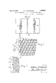
Fig. 7 represents on an enlarged scale a fragment of a completed shell, showing a preferred form and arrangement of perforations.
Fig. 8 represents a fragment of another such shell with perforations of somewhat different size and spacing from those shown in the preceding figures.
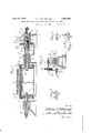
In Fig. 1, the cylindric metal shell A to be drilled is shown mounted in the machine in operative relation to mechanism for drilling the perforations in the shell. The drilling mechanism is represented by a gang of rotary drills 10. The supporting means for these drills, and the operating means by which the drills are caused to advance against and drill through the wall of the shell and then to reverse and withdraw therefrom, may be of any known or approved type. Such mechanism, being well understood in the art, is not herein specifically illustrated.
The drills operate successively on successively exposed parts of the shell. The illustrative machine embodies means whereby the successive relative positioning of the shell and drills for the successive drilling operations are so determined that the perforations are drilled in circumferentially extending lines oblique to a plane perpendicular to the shell axis, and more specifically according to a tion between the shell and drills.
relatively positioning the shell and drills acspiral. In this instance where the drilling is done with a longitudinal series of drills, the positioning action stated involves successively changing the angular relationship of the shell and drills, with accompanying relative movements in a longitudinal direc- In the illustrative machine these movements are so governed from position determining mechanism that any individual drill, as well as thewhole gang of drills, operates around the cylinder in a spiral course.
In Figs. 6 to 8, the line XY indicates a plane perpendicular to the axis of the shell A. The line XZ indicates a spiral accord- 1 ing to which the shell perforations are disposed. By drilling perforations in sequence around the cylinder on the line XZ and other perforations aligned with such first perforations in longitudinally extending 7 rows, with the centers of the perforations of the longitudinal rows uniformly spaced apart a distance equal to the pitch of said spiral, all the perforations thus drilled will lie on successive convolutions of the same spiral, as indicated in Fig. 6. This may be most conveniently and accurately done by successively drilling around the shell with a gang of uniformly spaced drills while successively cording to the course of a spiral, as is practiced in the illustrative machine.
Referring specifically to the illustrative machine the successive relative positioning of the shell A and drills 10 is therein ob tamed by combined rotative and longitudinal movements of the shell itself, the drills being mounted in a fixed support or carriage (not shown). For convenience the drills are represented as arranged above the shell, though in practice they would preferably be arranged at the side of the shell for clearance of chips.
The shell A is shown supported by heads 11 and 12, which are clamped to the ends of the shell by clamp members 13 and wedge rings 14. Bolts connecting the clamp members and heads are shown as long rods 15- extending through the hollow shafts carrying the heads. Said shafts, respectively des- 10C ignated 16 and 17, are in axial alignment and are slidable as well as rotatable in their respective bearings 18 and 19. The shaft 17 carrying the head 12 is connected with mechanism for successively imparting screw movements to said shaft for successively positioning the shell A'in relation to the drills. These movements are communicated through the shell .to the opposite head 11 which is floating or free to respond to the shell movements. Thehead 11 may also be shifted toward or away from the head 12 to permit mounting the shell in the machine or its removal therefrom.
For operating the shaft 17, a crank 20 is shown on the shaft of a pinion 21, which meshes with a gear 22 on the shaft of a worm 23, which drives the worm wheel 24 on said shaft 17. The shaft 17 slides in the worm wheel hub 25 which has keys engaging longitudinal keyways 26 in said shaft. A spacer .27 between the bearing 19 and the worm wheel hub prevents longitudinal displacement of the worm wheel. The screw portion 30 of the shaft 17 is engaged by a stationary nut 31, whereby the shaft is moved longitudinally as it is rotated. Said nut 31 is shown as an internally threaded bushing secured in the bearing 29 by diametrically opposite fastenings 32.
By the above described mechanism, the shaft 17 is operated through reduction gearing so that one complete revolution of the crank 20 will turn the shell A through only a small angle. At the same time the shell is moved longitudinally a correspondingly small fraction of the distance between successive threads of the screw 30. Thus, by successively operating. the crank, the shell A may be successively properly positioned for the successive drilling operations around the shell.
During each drilling operation, the crank 20 is held in a definite fixed position, as indicated in Fig. 2, thereby locking the operating means and holding the shell stationary. For this purpose, the crank handle 35 is carried on the shank of a spring pressed plunger 36 which normally engages a so-called index notch 37 in the machine frame. After every drilling operation, the plunger is disengaged from said index notch, and the crank is turned one complete revolution, allowing the plunger to snap back into the index notch. The shell is thereby accurately positioned and held for the ensuing drilling operation. The gearing between the crank 20 and shaft 17 determines the spacing between the centers of successive perforations around the shell; and the pitch of the screw 30 dedetermines the spiral course of the successively drilled longitudinal rows of perforations. By employing gearing such that every revolution of the crank will turn the shell through an angle which is a factor of 360, a certain number of crank revolutions will cause the shell'to make one complete rotation, and the successively drilled longitudinal rows of perforations will be uniformly spaced around the shell. By adopting a screw pitch such that the shell moves longitudinally during every complete rotation a distance which is either equal to or a factor or multiple of the distance between centers of adjacent drill spindles 10, the perforations made by every individual drill will be in a continuous spiral series with those made by other drills. For instance, assuming a given number of crank revolutions necessary to cause one complete rotation of the shell, and assuming that the drill spindles are spaced apart a distance between centers which is equal to the screwrpitch, as in the illustrative machine, then one complete rotation of a shell will bring it to position for the first or index drill 10 to register with the second perforation a in the first longitudinal row and for all the other drill spindles to register with corresponding perforations in said row. While the entire series of drills will thus operate around the cylinder a number of times, the pluralities of perforations made by each drill will be in a continuous spiral sequence with those made by other drills; and in the particular machine illustrated the perforations made by the several drills will be on successive convolutions of the same spiral. The pitch of the screw 30 may of course vary in different machines. For instance Fig. 3 indicates the thread of a screw for governing the drilling according to the spiral adopted in Fig. 7; while Fig. 4 indicates the thread of a screw for governing the irilling according to the spiral adopted in Fig. 6, represents the suction-roll shell with some of a series of perforations drilled in the manner explained, the perforations being in longitudinally extending rows with corresponding perforations of said rows on successive convolutions of a spiral line; the whole number of perforations being in a single spiral series winding around and around the cylinder, commencing at a at one end of the cylindler and terminating at a at the opposite en 7 After having drilled the spiral series of perforations shown in Fig. 6, other intermediate perforations may be drilled in a second spiral series by the following procedure: The crank 20 is detached and reafiixed on its shaft at a position 180 from its normal position, and is then revolved through a half turn to its original position shown in Fig. 2, allowing the plunger 36 to again engage the index notch 37. By this manipulation, the shell A will have been turned one half the distance between centers of adjacent longitudinal rows of perforations. The nut 31 is then unfastened and given a half turn in a direction to reverse the screw 30 and is then refastened in place. This manipulation will have moved the shell longitudinally half the distance between successive threads of the screw 30, i. e. half the distance between centers of adjacent perforations in the same longitudinal row. The shell is accordingly positioned so that the first or index drill 10 will drill the hole I; (Fig. 7). Commencing-with said hole I), the second series of perforations may then .be drilled in the same manner and with the same effect as the first, resulting in the product shown in Fig. 7. It will be observed in Fig. 7 that the longitudinal rows of perforations commencing at a and c alternate with -those commencing at band (i; and that the perforations a, c and a 0 are on successive convolutions of one spiral,-while the perforations 1), d and 6 d are on successive convolutions of another similar spiral. This arrangement obtains a greater number of perforations and closer spacing than could be obtained with a single series. The perforations in Fig. 7 are shown counter-bored at their outer ends, as is desirable in some cases, while the perforations in Fig. 8 are plain.
. After the shell has been perforated and removed from the machine, it may be desirable to replace it in the machine for furtherdrilling of the same perforations or counterboring or the like. In this connection, Fig. 5 shows a so-called indexing pin 40 inserted through a bushing in the shell supporting head 12 and into a hole 41 preliminarily drilled in the end of the shell A. This registers a determined point on the shell, e., g. the hole 41, with a determined point on the machine, e. g. the pin 40. If the shell perforating operation be initiated with the shell and head 12 thus related, and with the screw shaft 17 at a predetermined position, for instance its extreme retracted position, then after completion of the operation and removal of the shell it may be remounted in the machine in the same predetermined situation or relation to the machine parts, so that the first or index perforation a will have its center in exact registration with the center of the first or index drill 10; and thus all the perforations may be redrilled or further operated upon with the same or other drills by the procedure before explained.
The shell drilled in the manner described has its perforations in general centered on different transverse planes perpendicular to the shell axis. Obviously no two perforations on the same spiral line can lie in the same such plane. And by adopting a spiral of small pitch the said planes of the centers of the perforations will be closely adjacent. Thus in the operations of machining, grinding and polishing the shell, and in the operation of the shell in cooperation with a suctionbox in the completed suction-roll, the shell perforations will traverse the machining and grinding tools or the suction-box packings, as the case may be, at successively longitudinally ofi'set points, avoiding concentration of tools and obtaining a substantially uniform distribution of wear between the shell and box packings inthe completed suction-roll. The perforating operation may-also bevery -wear at particular points on the finishing conveniently and accurately practiced, and
tions distributed uniformly around the shell and at uniform distances apart longitudinally, but disposed in spiral instead of annular rows, and accomplishes this by successive operations of a longitudinally arranged gang of drills and intervening relative displace-. ments of the shell and drills by uniform rotative movements and uniform longitudinal movements so related to the drill spacing that a given number of operations will complete the drilling and the next work movement would bring the drills which are within the range of the perforated area into registration With previously drilled perforations, or in other words the spirally disposed sequence of perforations successively drilled by an individual drill will be-continuous with those similar sequences which are simultaneously drilled by a number ofand in this instance many other drills. This as compared with spirally drilling a cylinder by operating many times around and around the cylinder with a single drill, or with a gang of drills which drill perforations on separate and independent spirals, not only effects a tremendous saving of time and work but also has the great advantage of reducing the axial shift of the shell to a small amount. In the illustrative machine the axial shift is only the dispitch of thespiral were a multiple of this distance, for instance if successive pairs,
threes or other groups of the drills were em ployed for drilling perforations on two, threeor more intertwined spirals, or if for instance every other drill or pair of drills were omitted and the drills were accordingly operated twice instead of only once around the shell, the general principle and advantages of the invention would be utilized, there would be as in the illustrative machine a great saving of time, and the axial shift of thework would still be small as compared with the whole length of the perforated area or the whole length of the longitudinal gang of drills. It will be understood that the invention is not limited to the particular embodiment illus trated. In the claims, the word periodic as applied to the drill spacing is exemplified in the illustrative machine by the uniform drill spacing, and is to be understood as signifying that the drills are spaced uniformly apart or else in uniformly sp acedgroups with the spacing between groups a multiple of the distance between adjacent drills.
I claim as my invention:
1. A method of drilling a cylindric shell characterized by successively operating on the shell with a gang of uniformly spaced drills centered in a longitudinal line, and, in alternation with the drilling operations, successively shifting the relative positions of the shell and drills by relative rotative movements through aliquot fractions of a revolution and relative axial displacements for distances which are aliquot fractions of the distance between adjacent drill centers, whereby the holes successively drilled are disposed on a continuous spiral of a pitch corresponding to the spacing of the drill centers.
2. A method of drilling a cylindric shell involving the drilling of a series of perforations arranged in a continuous spiral of a plurality of convolutions, characterized by successively subjecting the shell to the operation of a plurality of drills arranged in a longitudinal row and uniformly spaced to drill holes centered on different convolutions of said spiral, and, in alternation with the drilling operations, successively shifting the relative positions of the shell and drills by relative displacements through aliquot fractions of a revolution and through aliquot fractions of a total axial displacement equal to the pitch of the spiral.
3. A shell drilling method characterized by successively operating on the shell with a longitudinally disposed series of periodically spaced drills and successively relatively positioning the shell and drills for successive drilling operations by successive equal increments of relative rotative and axial movements so related to the drill spacing that a given number of positionings will bring the drills within the range of the area to be perforated into registry each with a hole previously drilled by another of said drills, where'- by the said series of drills will have completed the drilling of a series of equally spaced perforations arranged according to the course of a continuous spiral of a plurality of convolutions about the shell, the said axial movements being aliquot fractions of the distance between adjacent drill centers.
4. A machine-for drilling a cylindric shell having, in combination, a gang of uniformly spaced drills arranged in a longitudinal row; means for holding the shell in operative relation to said drills; and means for successively shifting the relative positions of the shell and drills, between successive drilling operations, by relative rotative movements through aliquot fractions of a revolution and relative axial displacements which are aliquot fractions of the distance betweendrill row; means for successively relatively positioning the shell and drills for successive drilling operations by relative rotative and longitudinal movement so related to the drill spacing that the successively drilled holes are disposed according to the course of a continuous spiral of small pitch having a plurality of closely adjacent convolutions; and re-setting means whereby the machine may be organized to repeat its operations to drill a second like spiral series of holes in staggered relation to the first series.
6. A machine of the class described comprising, in combination, shell supporting means; a gang of drills disposed longitudinally of the shell for successively drilling pluralities of holes therein; means for effecting relative rotation between the shell and drills in successive equal stages of partial rotative movement; means for effecting relative longitudinal movement between the shell and drills in successive slight equal stages of such movement; the shell and drills being successively related for successive drilling operations by the successive relative rotative and longitudinal movements and the drills being so spaced in relation to the successive movements that the positioning movement after a given number of operations will bring the drills within the range of the perforated area into registry each with a hole previously drilled by another of the drills, whereby the holes drilled by the gang of drills in a given succession of operations will be disposed according to the course of a continuous spiral having a plurality of convolutions.
7. A machine of the class described comprising, in combination, shell supporting means; a gang of drills disposed longitudinally of the shell for successively drilling pluralities of holes therein; means for effecting relative rotationb-etween the shell and drills in successive equal stages of partial rotative movement; means for effecting relative longitudinal movement between the shell and drills in successive slight equal stages of such movement; the shell and drills being successively related for successive T drilling operations by the successive relative rotative and longitudinal movements; and the drills being so spaced in relation to the successive movements that the holes drilled by the gang of drills in a given succession of operations will be.disposed according to the course of a continuous spiral having a drills whereby it may be re-set for drilling a second like series of holes with the same drills, the aforesaid means for elfecting relative rotative and longitudinal movements in stages being likewise operable when the machine is re-set.
8. A machine of the class described comprising, in combination, shell supporting means; a gang of drills disposed longitudinally of the shell for successively drilling pluralities of holes therein; means for effecting relative rotation between the shell and drills in successive equal stages of partial rotative movement; means for effecting relative longitudinal movement between the shell and drills in successive slight equal stagesof such movement; the shell and drills being successively related for successive drilling operations by the successive relative rotative and longitudinal movements; and the drills being so spaced in relation to the successive movements that the holes drilled by the gang of drills in a given succession of operations will be disposed according to the course of a continuous spiral having a plurality of convolutions; the machine embodying means operable to effect a relative shift between the shell and drills through a relative rotary movement of one-half the amount of one of I the machine being organized and arranged so that the successive motions of the screw. impart like relative motions between the shell and drills, wherebyizhe shell and drills are successively related for successive drilling operations; the drills being so spaced in relation to the pitch of the screw that after a given number of operations individual drills will re 'ster each with a hole previously drilled y another drill and the holes drilled by the gang of drillsin a given succession of operations will be disposed according to the course of a continuous spiral having a plurality of convolutions.
10. A machine of the class described comprising, in combination, a gang of drills disposed longitudinally for successively drilling pluralities of holes in the shell; shell supportmg means comprising rotatable shell-clamping heads mounted to permit movement of the heads and shell in an axial direction; a screw connected with one of said heads; means for successively operating said screw by equal partial step-by-step rotative movements. whereby a corresponding step-by-step screw motion is imparted to the shell; the drills being so spaced in relation to'the pitch of the screw that after a given number of operations individual drills will register each with a hole previously drilled by another drill and the holes drilled by the gang of drills in a given succession of operations will be disposed according to the course of a continuous spiral having a plurality of convolutions. Y
11. A machine for drilling a cylindric shell having, in combination, a gang of uniformly spaced drills arranged in a longitudinal row; means for holding the shell in operative relation to said drills; and means for successively shifting the relative positions of the shell and drills, between'successive drilling operations, by equal relative rotative movements and equal relative longitudinal displacements, the total longitudinal displacement being equal' to the distance between adjacent drill centers, whereby the holes formed by the drills are disposed on a continuous spiral.
12. A machine for drilling perforations in a suction roll shell, comprising a longitudinally arranged gang of periodically spaced drills for operating successively on the shell at diflferent relative positions between the shell and drills, and means whereby the successive relative positions of the shell and drills are effected by relative movements both rotatively and longitudinally in successive predetermined stages, the total longitudinal displacement being for a distance which is only a relatively small part of the entire length of the portion of the shell to be drilled, the periodic spacing of the drillsbeinginsuch relation to the movements that after a given succession of operations individual drills will register each with a perforation previously made by another drill; whereby longitudinally extending rows of perforations are successively drilledwith corresponding perforations of the rows disposed on a continuous spiral.
13. A method of drilling a cylindric shell, involving the drilling of a series of perforations arranged in a continuous spiral of a plurality of convolutions, characterized by successively operating on the shell with a plurality of drills centered todrill holes on difierent convolutions of such spiral, and successively relatively positioning the shell and drills for successive drilling operations by successive increments of relative rotative and longitudinal movements such that after a given succession of operations individual drills will register each with a perforation previously drilled by another drill and the continuous spiral.
holes formed by the drills will be on such 14. A shell drilling machine embodying a longitudinally arranged series of uniformly spaced drills and mechanism for successively relatively positioning the work and drills for successive drilling operations by equal increments of relative rotative and axial movements so related to the drill spacing that after a given number of operations the said drills will have completed the drilling of a series of holes centered on a continuous spiral of a plurality of convolutions about the shell and the ensuing positioningv movement would bring the drills in the range of the perforated area into registry each with a hole previously drilled by another of the said series of drills, the said axial movements being aliquot fractions of the distance between adjacent drill centers.
15. A shell drilling machine embodying a longitudinally arranged series of periodically spaced drills and mechanism for successively relatively positioning the work and drills for successive drilling operations by equal increments of relative rotative and axial movements so related to the drill spacing that the positioning movement following a given number of drilling operations will bring the drills in the range of the perforated area into registry each with a hole previously drilled by another of the series of drills, so that the drills in the said number of operations will have perforated the shell with uniformly spaced perforations disposed according to the course of a continuous spiral of a plurality of convolutions about the shaft, the said axial movements being aliquot fractions of the distance between adjacent drill centers.
16. A shell drilling machine embodying a longitudinally arranged series of periodically spaced drills and mechanism for successively relatively positioning the work and drills for successive drilling operations by equal increments of relative rotative and axial movements so related to the drill spacing that the positioning movement following a given number of drilling operations will bring the drills in the range of the perforated area into registry each with a hole previously drilled by another of the series of drills, so that the drills in the said number of operations will have perforated the shell with uniformly spaced perforations disposed according to the course of a continuous spiral of a plurality of convolutions about the shell, and resetting means whereby the machine may be organized to repeat its operations to drill a second like spiral series of holes in staggered relation to the first series, the said axial movements being aliquot fractions of the distance between adjacent drill centers.
17. A machine for drilling a cylindric shell having, in combination, a gang of uniformly spaced drills arranged in a longitudinal row; means for holding the shell in operative relation to said drills; and means for successively shifting the relative positions of the shell and drills, between successive drilling operations, by equal relative rotative movements and equal relative longitudinal displacements, the total longitudinal displacements being equal to the distance between adjacent drill centers whereby the successively drilled holes are disposed according to the course of a spiral, the ratio of the pitch of the spiral to the distance between adjacent drill centers being a whole number.
18. A. machine for drilling perforations in a suction-roll shell, comprising a longitudinally arranged gang of periodically spaced drills for operating successively on the shell at difierent relativepositions betweenthe shell and drills, and means whereby the successive relative positions of the shell and drills are efiected by relative movements both rotatively and longitudinally in successive predetermined stages, the total longitudinal displacement being for a distance which is only a relatively small part of the entire length of the portion of the shell to be drilled; the periodic spacing of the drills being in such relation to the movements thatafter a given succession of operations individual drills will register each with-a perforation previously made by another drill, whereby longitudinally extending rows of perforations are successively drilled with corresponding perforations of the rows disposed according to a spiral course.
19. A shell drilling machine embodying a longitudinally arranged series of uniformly spaced drills and mechanism for successively relatively positioning the work and drills for successive drilling operations by equal increments of relative rotative and axial movements so related to the drill spacing that the successively drilled holes are disposed according to a spiral course and after a given number of operations the ensuing positioning movement will bring the drills in the range of the perforated area into registry each with a hole previously drilled by another of the said serles of drills.-
20. A shell drilling machine embod ing a longitudinally arranged series of uni ormly spaced drills and mechanism for successively relatively positioning the work and drills for successive drilling operations by relative rotative movements through aliquot fractions of a revolution and by relative axial displacements such that successively drilled holes are disposed according to the course of a spiral, the ratio of the pitch of said spiral to the distance between adjacent drill centers being a whole number.
21. A shell drilling machine embodying a longitudinally arranged series of uniformly spaced drills and mechanism for successively relatively positioning the work and drills for successive drilling operations by relative rotative movements through aliquot fractions of a revolution and by relative axial displacements such that successively drilled holes are disposed according to the courseof a. spiral, the ratio of the distance between adjacent drill centers to the pitch of said spiral being a Whole number.
In testimony whereof I aflix my signature.
WILLIAM H. MILLSPAUGH.
Priority Applications (3)
| Application Number | Priority Date | Filing Date | Title |
|---|---|---|---|
| US141750A US1854053A (en) | 1926-10-15 | 1926-10-15 | Method and machine for perforating suction-roll shells |
| GB27842/26A GB279643A (en) | 1926-10-15 | 1926-11-05 | Improvements in suction-roll shells and methods and machines for perforating the same |
| DEM97786D DE514212C (en) | 1926-10-15 | 1927-01-08 | Machine for drilling holes in cylinder sleeves |
Applications Claiming Priority (2)
| Application Number | Priority Date | Filing Date | Title |
|---|---|---|---|
| US141750A US1854053A (en) | 1926-10-15 | 1926-10-15 | Method and machine for perforating suction-roll shells |
| GB27842/26A GB279643A (en) | 1926-10-15 | 1926-11-05 | Improvements in suction-roll shells and methods and machines for perforating the same |
Publications (1)
| Publication Number | Publication Date |
|---|---|
| US1854053A true US1854053A (en) | 1932-04-12 |
Family
ID=26259032
Family Applications (1)
| Application Number | Title | Priority Date | Filing Date |
|---|---|---|---|
| US141750A Expired - Lifetime US1854053A (en) | 1926-10-15 | 1926-10-15 | Method and machine for perforating suction-roll shells |
Country Status (3)
| Country | Link |
|---|---|
| US (1) | US1854053A (en) |
| DE (1) | DE514212C (en) |
| GB (1) | GB279643A (en) |
Cited By (9)
| Publication number | Priority date | Publication date | Assignee | Title |
|---|---|---|---|---|
| US3111455A (en) * | 1961-05-29 | 1963-11-19 | Sandusky Foundry & Machine Com | Suction roll shell and method of making same |
| US4674925A (en) * | 1986-10-03 | 1987-06-23 | Ashcombe Products Company | Gang drill and method for clearing patterns of holes in tubular members |
| US5090846A (en) * | 1990-03-19 | 1992-02-25 | Valmet Paper Machinery Inc. | Method and apparatus for drilling of holes into the mantle of a cylinder |
| US5092715A (en) * | 1989-02-13 | 1992-03-03 | Societe De Construction Des Avions Hurel-Duobis | Method of piercing a plate, of any configuration, with a very high perforation density and products thus obtained |
| WO1999033599A1 (en) * | 1997-12-29 | 1999-07-08 | Pikoteknik Oy | Method of drilling holes in a dryer cylinder |
| US6254318B1 (en) * | 1998-12-16 | 2001-07-03 | Michael F. Sica | Apparatus for making numerous holes in a tube |
| US6264405B1 (en) * | 1997-04-03 | 2001-07-24 | Valmet Corporation | Method and device for drilling holes into the mantle of a cylinder or equivalent of a paper machine |
| US6789984B1 (en) * | 1998-07-13 | 2004-09-14 | Pikoteknik Oy | Process and apparatus for drilling holes in the shell of a cylinder |
| US6884323B2 (en) * | 2003-01-31 | 2005-04-26 | Voith Paper Patent Gmbh | Vented main roll for press assembly in a paper machine |
-
1926
- 1926-10-15 US US141750A patent/US1854053A/en not_active Expired - Lifetime
- 1926-11-05 GB GB27842/26A patent/GB279643A/en not_active Expired
-
1927
- 1927-01-08 DE DEM97786D patent/DE514212C/en not_active Expired
Cited By (10)
| Publication number | Priority date | Publication date | Assignee | Title |
|---|---|---|---|---|
| US3111455A (en) * | 1961-05-29 | 1963-11-19 | Sandusky Foundry & Machine Com | Suction roll shell and method of making same |
| US4674925A (en) * | 1986-10-03 | 1987-06-23 | Ashcombe Products Company | Gang drill and method for clearing patterns of holes in tubular members |
| US5092715A (en) * | 1989-02-13 | 1992-03-03 | Societe De Construction Des Avions Hurel-Duobis | Method of piercing a plate, of any configuration, with a very high perforation density and products thus obtained |
| US5090846A (en) * | 1990-03-19 | 1992-02-25 | Valmet Paper Machinery Inc. | Method and apparatus for drilling of holes into the mantle of a cylinder |
| US6264405B1 (en) * | 1997-04-03 | 2001-07-24 | Valmet Corporation | Method and device for drilling holes into the mantle of a cylinder or equivalent of a paper machine |
| WO1999033599A1 (en) * | 1997-12-29 | 1999-07-08 | Pikoteknik Oy | Method of drilling holes in a dryer cylinder |
| US6375394B1 (en) | 1997-12-29 | 2002-04-23 | Pikoteknik Oy | Method of drilling holes in a dryer cylinder |
| US6789984B1 (en) * | 1998-07-13 | 2004-09-14 | Pikoteknik Oy | Process and apparatus for drilling holes in the shell of a cylinder |
| US6254318B1 (en) * | 1998-12-16 | 2001-07-03 | Michael F. Sica | Apparatus for making numerous holes in a tube |
| US6884323B2 (en) * | 2003-01-31 | 2005-04-26 | Voith Paper Patent Gmbh | Vented main roll for press assembly in a paper machine |
Also Published As
| Publication number | Publication date |
|---|---|
| GB279643A (en) | 1927-11-03 |
| DE514212C (en) | 1930-12-09 |
Similar Documents
| Publication | Publication Date | Title |
|---|---|---|
| US1854053A (en) | Method and machine for perforating suction-roll shells | |
| US1498748A (en) | Ball race | |
| US3249015A (en) | Method and apparatus for truing rotary members | |
| US2360235A (en) | Grinding machine | |
| US1725342A (en) | Centering chuck | |
| US2385498A (en) | Apparatus for forming integral finned tubing | |
| US2791136A (en) | Indexing drum for drill press | |
| US3727443A (en) | Ball swage for reducing tubes | |
| US1925911A (en) | Method of grinding crank shafts | |
| US859644A (en) | Threading-tool. | |
| US606837A (en) | gibson | |
| US1240914A (en) | Gear-rolling machine. | |
| US2791822A (en) | Single spindle automatic screw machine | |
| US1740149A (en) | Multiple-spindle drilling machine | |
| US1013489A (en) | Method for making spiral latticed poles or the like. | |
| US976880A (en) | Left-hand-threading device. | |
| US230825A (en) | Machine for cutting screw-threads | |
| US1304906A (en) | Means | |
| SU650786A1 (en) | Semiautomatic rotor drilling machine | |
| US1881522A (en) | Workhead | |
| US1745035A (en) | Machine for milling threads | |
| SU380439A1 (en) | MULTIPLE TOOL FOR MICRORELIEF EDUCATION | |
| US1957028A (en) | Machine tool for generating the teeth of bevel gears | |
| US1683868A (en) | Machine for truing gears | |
| US2012677A (en) | Spindle structure |