EP0972296B1 - Metal-oxygen-carbon field emitters - Google Patents
Metal-oxygen-carbon field emitters Download PDFInfo
- Publication number
- EP0972296B1 EP0972296B1 EP98922020A EP98922020A EP0972296B1 EP 0972296 B1 EP0972296 B1 EP 0972296B1 EP 98922020 A EP98922020 A EP 98922020A EP 98922020 A EP98922020 A EP 98922020A EP 0972296 B1 EP0972296 B1 EP 0972296B1
- Authority
- EP
- European Patent Office
- Prior art keywords
- metal
- wire
- oxygen
- field emission
- whiskers
- Prior art date
- Legal status (The legal status is an assumption and is not a legal conclusion. Google has not performed a legal analysis and makes no representation as to the accuracy of the status listed.)
- Expired - Lifetime
Links
Images




Classifications
-
- H—ELECTRICITY
- H01—ELECTRIC ELEMENTS
- H01J—ELECTRIC DISCHARGE TUBES OR DISCHARGE LAMPS
- H01J1/00—Details of electrodes, of magnetic control means, of screens, or of the mounting or spacing thereof, common to two or more basic types of discharge tubes or lamps
- H01J1/02—Main electrodes
- H01J1/30—Cold cathodes, e.g. field-emissive cathode
-
- H—ELECTRICITY
- H01—ELECTRIC ELEMENTS
- H01J—ELECTRIC DISCHARGE TUBES OR DISCHARGE LAMPS
- H01J1/00—Details of electrodes, of magnetic control means, of screens, or of the mounting or spacing thereof, common to two or more basic types of discharge tubes or lamps
- H01J1/02—Main electrodes
- H01J1/30—Cold cathodes, e.g. field-emissive cathode
- H01J1/304—Field-emissive cathodes
-
- H—ELECTRICITY
- H01—ELECTRIC ELEMENTS
- H01J—ELECTRIC DISCHARGE TUBES OR DISCHARGE LAMPS
- H01J9/00—Apparatus or processes specially adapted for the manufacture, installation, removal, maintenance of electric discharge tubes, discharge lamps, or parts thereof; Recovery of material from discharge tubes or lamps
- H01J9/02—Manufacture of electrodes or electrode systems
- H01J9/022—Manufacture of electrodes or electrode systems of cold cathodes
- H01J9/025—Manufacture of electrodes or electrode systems of cold cathodes of field emission cathodes
Definitions
- the invention generally relates to metal-oxygen-carbon field emitters and particularly to their use in a field emitter cathode for display panels.
- a process for making metal-oxygen-carbon whisker field emitters is also provided.
- Field emission electron sources can be used in a variety of electronic applications, e.g., vacuum electronic devices, flat panel computer and television displays, emission gate amplifiers, and klystrons and in lighting.
- Display panels are used in a wide variety of applications such as home and commercial televisions, laptop and desktop computers and indoor and outdoor advertising and information presentations.
- Flat panel displays are only a few inches thick in contrast to the deep cathode ray tube monitors found on most televisions and desktop computers.
- Flat panel displays are a necessity for laptop computers, but also provide advantages in weight and size for many of the other applications.
- laptop computer flat panel displays use liquid crystals which can be switched from a transparent state to an opaque one by the application of small electrical signals. It is difficult to reliably produce these displays in sizes larger than that suitable for laptop computers.
- Plasma displays have been proposed as an alternative to liquid crystal displays.
- a plasma display uses tiny cells of electrically charged gases to produce an image and requires relatively large electrical power to operate.
- whiskers from graphite surfaces under ion sputtering conditions. They note that the whiskers of smallest diameter, characteristically about 15 nm, definitely appear to be different from either diamond or the scrolled-graphite structure found in carbon fibers grown by catalytic pyrolysis of hydrocarbons. Larger whiskers with diameters ranging from 30 to 100 nm were also observed to grow in sputtering systems. The smaller diameter whiskers are constant in diameter along the length while the larger diameter whiskers may have a slight taper.
- filaments may be grown on several types of hexagonal carbon surfaces, but not on diamond or glassy carbon.
- the invention also provides a field emission cathode comprising a metal, oxygen and carbon field emission electron emitter composition, as described above, attached to a metal substrate.
- the field emission electron emitter composition is in the form of whiskers.
- a is from about 0.2 to about 0.4
- b is from about 0.4 to about 0.8
- c is from about 0.05 to about 0.3.
- the metal is tungsten, iron or molybdenum.
- a process for making the metal-oxygen-carbon whiskers of the invention comprises heating a metal substrate, preferably a metal wire, coated with an organic polymer, such as polyacrylonitrile (PAN), to a temperature of from about 1100°C to about 1550°C in an inert atmosphere and maintaining that temperature for about 15 minutes to about two (2) hours.
- PAN polyacrylonitrile
- the temperature is from about 1150°C to about 1300°C and the atmosphere comprises argon.
- temperatures as low as 550°C can be used with heating times up to three (3) hours.
- Suitable catalysts include nickel, copper-nickel alloys and cobalt-nickel alloys.
- the field emission electron emitter compositions and field emission cathodes are useful in vacuum electronic devices, flat panel computer and television displays and other large screen applications, emission gate amplifiers, klystrons and lighting devices.
- display panel embraces planar (e.g., flat panel displays) and curved surfaces as well as other possible geometries).
- the metal-oxygen-carbon whiskers useful as electron emitters in the invention can be formed by coating a metal substrate (e.g., metal wire) with an organic polymer and heating the coated wire, e.g., by coating the wire with a polyacrylonitrile (PAN) solution and heating the PAN coated wire to form the whiskers.
- Wires containing such whiskers are especially useful in fibrous field emission cathodes in which each fiber or wire of the fibrous cathode lies essentially in the plane of the cathode so that electron emission occurs along the length of the fiber or wire and not from the tip or end of the fiber or wire.
- the heating of the PAN coated wire to form the whiskers can be carried out before or after the wires are positioned on the cathode structure.
- the metal wire Prior to the application of the PAN solution coating, the metal wire is cleaned in 30 wt. % nitric acid solution for 30 minutes followed by de-ionized water, acetone and methanol rinses.
- the metal is tungsten, iron or molybdenum.
- PAN is preferably coated onto the wire from a solution of polyacrylonitrile in dimethyl sulfoxide. The heated solution is stirred until the polymer is fully dissolved and then cooled to ambient temperature. The viscous PAN solution is then applied to the clean metal wire with a small brush. The wire coated with the PAN layer is stabilized, typically, by heating in an oven to 250°C and maintaining that temperature for about 30 minutes. A second layer of PAN solution is then applied to the PAN-coated wire and again stabilization is accomplished by heating in an oven to 250°C and maintaining that temperature for about 30 minutes.
- the PAN-coated wire is then heated to a temperature of from about 1100°C to about 1550°C and maintained at that temperature for about 15 minutes to about two (2) hours to form the metal-oxygen-carbon whiskers.
- This heating is carried out in an atmosphere of an inert gas, such as argon, in an atmosphere of ethylene, carbon monoxide or carbon dioxide or in an atmosphere comprising mixtures of these gases.
- the formation of the metal-oxygen-carbon whiskers can be carried out at lower temperatures in the presence of a catalyst such as a copper-nickel alloy, a cobalt-nickel alloy or nickel. Temperatures as low as 550°C can be used with these catalysts with heating times up to about three (3) hours.
- a catalyst such as a copper-nickel alloy, a cobalt-nickel alloy or nickel.
- the surface structure of the wire changes significantly during heating. As a consequence of heating, the surface is no longer smooth, but instead is comprised of metal-oxygen-carbon whiskers attached to the metal wire.
- the density or spacing of these whiskers and their shape depend on the heating conditions.
- the lengths of the metal-oxygen-carbon whiskers can extend from less than 2 ⁇ m to 20 ⁇ m or more. Diameters of the whiskers are typically in the range of about 1 nm to about 1 ⁇ m.
- Electron emission from wires containing metal-oxygen-carbon whiskers was measured in a cylindrical test fixture.
- the conducting wire to be tested served as the cathode and is mounted in the center of a cylinder which served as the anode.
- This anode cylinder typically consists of a fine mesh cylindrical metal screen coated with a phosphor. Both the cathode and anode are held in place by an aluminum block with a semi-cylindrical hole cut therein.
- the conducting wire is held in place by two 0,16 cm (1/16 inch) diameter stainless steel tubes, one at each end. These tubes are cut open at each end, forming an open trough in the shape of a half cylinder of length 1,27 cm (1/2 inch) and diameter 0,16 cm (1/16) inch, and the wire is placed in the open trough that results and held in place with silver paste.
- the connecting tubes are held in place within the aluminum block by tight fitting polytetrafluoroethylene (PTFE) spacers, which serve to electrically separate the anode and cathode.
- the total length of exposed wire is generally set at 1.0 cm, although shorter or longer lengths could be studied by controlling the placement of the holder tubes.
- the cylindrical screen mesh anode is placed in the semi-cylindrical trough in the aluminum block and held in place with copper tape.
- the cathode is in electrical contact with the aluminum block.
- Electrical leads are connected to both the anode and cathode.
- the anode is maintained at ground potential (0 V) and the voltage of the cathode is controlled with a 0-10 kV power supply.
- Electrical current emitted by the cathode is collected at the anode and measured with an electrometer.
- the electrometer is protected from damaging current spikes by an in-series 1 M1 ⁇ 2 resistor and in-parallel diodes which allow high current spikes to bypass the electrometer to ground.
- Samples for measurement of about 2 cm in length are cut from longer lengths of wire. With the cylindrical screen mesh anode removed, the samples are inserted into the cylindrical troughs of the two holder arms. Silver paste is applied to hold them in place. The silver paste is allowed to dry and the cylindrical screen mesh anode is reattached and held in place with copper tape at both ends.
- the test apparatus is inserted into a vacuum system, and the system is evacuated to a base pressure below 1 x 10 -6 torr (1.3 x 10 -4 Pa).
- Emission current is measured as a function of applied voltage. Electrons emitted from the cathode create light when they strike the phosphor on the anode. The distribution and intensity of electron emission sites on the wire can be observed by the pattern of light created on the phosphor/wire mesh screen.
- the metal-oxygen-carbon whiskers produced provide good emission and can be formed on metal substrate surfaces other than wires.
- the invention is applicable to both planar and fibrous/wire substrates as well as other possible geometries.
- the metal surface can be a single metal or a metal alloy in the form of a wire or a sheet.
- the metal surface can be thick film conductor material such as that obtained using diffusion patterning techniques (e.g., the Diffusion PatterningTM system QM14 Ag or QM17 Ag/Pt imaging pastes (commercially available from E. I. du Pont de Nemours and Company, Wilmington, DE) or photoprintable compositions such as FODEL® 5956 gold conductor composition (commercially available from E. I. du Pont de Nemours and Company, Wilmington, DE).
- diffusion patterning techniques e.g., the Diffusion PatterningTM system QM14 Ag or QM17 Ag/Pt imaging pastes (commercially available from E. I. du Pont de Nemours and Company, Wilmington, DE) or photoprintable compositions such as FODEL® 5956 gold conductor composition (commercially available from E. I. du Pont de Nemours and Company, Wilmington, DE).
- Tungsten wires 4 mil (0.1 mm) in diameter were cleaned in 30 wt. % nitric acid solution for 30 minutes followed by abundant deionized water, acetone and methanol rinses.
- the polyacrylonitrile layer was coated onto the wires from solution.
- the solution was prepared by mixing 8 g of polyacrylonitrile (PAN) (commercially available from Aldrich, Milwaukee, WI) into 100 g of dimethyl sulfoxide at 80°C. The heated solution was stirred until the polymer was fully dissolved and then cooled to ambient temperature. The resulting viscous PAN solution was then applied to the clean tungsten wires with a small brush.
- the PAN layer coating on each wire was stabilized by heating in an oven at 250°C for 30 minutes in air.
- a second PAN layer was brushed onto the stabilized first layer of each wire. Stabilization of the second PAN layer was carried out by heating in an oven at 250°C for 30 minutes in air.
- the wire samples with stabilized PAN were placed in a 6 inch (15 cm) long ceramic crucible and heated in a tube furnace in an argon atmosphere for 30 minutes. Only the temperature to which the samples were heated differ.
- the sample of Comparative Experiment A was heated to 1000°C and those of Examples 1-4 were heated to temperatures of 1100°C (Example 1), 1250°C (Example 2), 1400°C (Example 3) and 1550°C (Example 4), respectively. No catalyst was present in any of these samples.
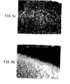
- the thickness or diameter of the whiskers is reduced and they are mainly perpendicular to the surface of the wire, i.e., aligned along extended radii of the wire.
- the thickness or diameter of the whiskers is increased and the whiskers tend to lie along or tangent to the surface of the wire pointing in various directions.
- Electron emission was then measured in the cylindrical test fixture described previously.
- the length of exposed whisker-coated wire was 1 cm.
- Emission characteristics for the samples of Examples 1-4 and Comparative Experiment A are shown in Figure 2 and demonstrate the improved emission properties resulting from the tungsten-oxygen-carbon whiskers.
- Tungsten wire 2 mil (0.05 mm) and 4 mil (0.1 mm) in diameter was used for the samples of Examples 5 and 6, respectively.
- the tungsten wire was cleaned and coated with a PAN layer and the PAN layer stabilized essentially as described in Examples 1-4 and Comparative Experiment A.
- the wire samples with the stabilized PAN coatings were placed in a 6 inch (15 cm) long ceramic crucible and heated in a tube furnace in an argon atmosphere to a temperature of 1300°C and maintained at that temperature for 30 minutes to form the tungsten-oxygen-carbon whiskers.
- the scanning electron micrographs for the sample of Example 5 ( Figure 3a) and that for Example 6 ( Figure 3b) clearly show whiskers of various diameters, lengths and orientations on both the 2 mil (0.05 mm) and 4 mil (0.1 mm) tungsten wire.
- Electron emission was measured in the cylindrical test fixture described previously. Emission characteristics for the samples of these Examples are shown in Figure 4. The onset of emission for the wire with the smaller diameter (Example 5) occurs at a lower voltage than that for the wire with the larger diameter (Example 6).
- Iron wires 2 mil (0.05 mm) in diameter were coated with two layers of polyacrylonitrile.
- the wires used in Examples 7 and 8 were cleaned in acetone followed by a methanol rinse.
- the wires used in Examples 9 and 10 were also cleaned in acetone followed by a methanol rinse and were then were reduced in a 2 vol. %H/98 vol. % Ar atmosphere at 250°C for 2 hours.
- a viscous PAN solution essentially identical to that used in Examples 1-4 and Comparative Experiment A, was then applied to the iron wires with a small brush.
- the PAN layer coating on each wire was stabilized by heating in an oven at 250°C for 30 minutes in an argon atmosphere.
- the PAN layer coating on each wire was stabilized by heating in an oven at 250°C for 30 minutes in a 2 vol. %H/98 vol. % Ar reducing atmosphere.
- a second PAN layer was brushed onto the stabilized first layer of each wire.
- stabilization of the second PAN layer was carried out by heating in an oven at 250°C for 30 minutes in an argon atmosphere.
- stabilization of the second PAN layer was carried out by heating in an oven at 250°C for 30 minutes in a 2 vol. %H/98 vol. % Ar reducing atmosphere.
- the wire samples with the stabilized PAN coatings were placed in a 6 inch (15 cm) long ceramic crucible and heated in a tube furnace to form the iron-oxygen-carbon whiskers.
- 100 mgr. of 50 wt. % Cu/50 wt. % Ni alloy (commercially available from Goodfellow Corporation, Cambridge, U. K.) were also placed in the crucible. Approximately 5 wt. % for the alloy was consumed during firing.
- the coated wire was heated in a CO 2 atmosphere to a temperature of 700°C and maintained at that temperature for 60 minutes.
- Example 8 the coated wire was heated in a 2 vol. % ethylene/98 vol. % argon atmosphere to a temperature of 750°C and maintained at that temperature for 120 minutes.
- Example 9 the coated wire was heated in a CO atmosphere to a temperature of 700°C and maintained at that temperature for 60 minutes.
- the coated wire was heated in a 2 vol. % ethylene/98 vol. % argon atmosphere at 550°C and maintained at that temperature for 90 minutes.
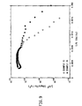
- Electron emission was measured in the cylindrical test fixture described previously. Emission characteristics for the samples of these Examples are shown in Figure 6. The emission results show that emitters can be produced by lower temperature processing when heating is carried out in the presence of a catalyst. The results for Example 9 also show that a wire heated in a CO atmosphere has considerably higher emission.
- Example 11 and 12 were prepared essentially as described for Examples 5 and 6, respectively, and the results were essentially the same, i.e., the formation of tungsten-oxygen-carbon whiskers on tungsten wire 2 mil (0.05 mm) and tungsten wire 4 mil (0.1 mm) in diameter, respectively.
- a tungsten wire 4 mil (0.1 mm) in diameter was used for the sample of Example 13 .
- the wire was cleaned and coated with a PAN layer and the PAN layer stabilized essentially as were the samples of Examples 11 and 12 except that following the stabilization of the second PAN layer by heating in the oven at 250°C for 30 minutes in air, an additional stabilization step was performed by heating in the oven at 550°C for 30 minutes in air.
- the sample for Comparative Experiment B was prepared essentially as those for Examples 5 and 11 except that the final heating was carried out at 1000°C for 30 minutes in an argon atmosphere rather than at 1300°C.
- iron wire 2 mil (0.05 mm) in diameter was cleaned with acetone followed by a methanol rinse and was reduced in a 2 vol. %H/98 vol. % argon atmosphere for 2 hours at 250°C.
- the uncoated iron wire was heated in the presence of a 55 wt. % Cu/45 wt. % Ni alloy catalyst in a CO atmosphere to a temperature of 550°C and maintained at that temperature for 90 minutes.
- Example 14 the reduced wire was coated with a 6 wt. % solution of Elvaloy® 4043, a resin modifier (commercially available from E. I. du Pont de Nemours and Company, Wilmington, DE) in methylene chloride.
- Elavaloy® is a copolymer of methylmethacrylate/ethylene and CO.
- the uncoated reduced wire of Example 15 was heated at 550°C for 90 minutes in a CO atmosphere and in the presence of a 55 wt. % Cu/45 wt. % Ni catalyst. This wire was then coated with a 5 wt. % poly(methylmethacrylate) in methylene chloride solution to a thickness of 3 microns.
- the coated wires of Examples 14 and 15 were then heated in the presence of a 55 wt. % Cu/45 wt. % Ni alloy catalyst in a CO atmosphere to a temperature of 550°C and maintained at that temperature for 90 minutes.
Landscapes
- Engineering & Computer Science (AREA)
- Manufacturing & Machinery (AREA)
- Cold Cathode And The Manufacture (AREA)
- Crystals, And After-Treatments Of Crystals (AREA)
Description
| Atomic % | ||||||
| Sample | Heating Temp. (°C) | W | 0 | C | Voltage (V) | I (µA) |
| Example 11 | 1300 | 21.10 | 51.46 | 27.43 | 800 | 80 |
| Example 12 | 1300 | 24.03 | 42.51 | 33.45 | 750 | 150 |
| Example 13 | 1300 | 21.07 | 54.98 | 23.94 | 1400 | 25 |
| Comp. Ex. B | 1000 | 0.01 | 9.83 | 90.16 | 2900 | 0 |
Claims (18)
- A field emission electron emitter composition comprising metal, oxygen and carbon, wherein the atomic ratio of metal:oxygen:carbon is a:b:c where a is from about 0.1 to about 0.4, b is from about 0.1 to about 0.8 and c is from about 0.05 to about 0.8 with the provisio that a + b + c = 1.
- The field emission electron emitter composition of Claim 1, wherein a is from about 0.2 to about 0.4, b is from about 0.4 to about 0.8 and c is from about 0.05 to about 0.3 with the provisio that a + b + c = 1.
- The field emission electron emitter composition of Claims 1 or 2, wherein said composition is in the form of whiskers.
- The field emission electron emitter composition of Claim 3, wherein said metal is tungsten, iron or molybdenum.
- A field emission cathode comprising a field emission electron emitter composition comprising metal, oxygen and carbon attached to a substrate of the same metal, wherein the atomic ratio of metal:oxygen:carbon in said composition is a:b:c where a is from about 0.1 to about 0.4, b is from about 0.1 to about 0.8 and c is from about 0.05 to about 0.8 with the provisio that a + b + c = 1.
- The field emission cathode of Claim 5, wherein a is from about 0.2 to about 0.4, b is from about 0.4 to about 0.8 and c is from about 0.05 to about 0.3 with the provisio that a + b + c = 1.
- The field emission cathode of Claims 5 or 6, in which said substrate is in the form of a wire.
- The field emission cathode of Claim 7, wherein said composition is in the form of whiskers.
- The field emission cathode of Claim 8, wherein said metal is tungsten, iron or molybdenum.
- A process for producing a field emission cathode comprising heating a polyacrylonitrile coated metal substrate to a temperature of from about 1100°C to about 1550°C and maintaining said temperature for about 15 minutes to 2 hours.
- The process of Claim 10, wherein said metal is tungsten, iron or molybdenum.
- The process of Claim 11, wherein said temperature is from about 1150°C to about 1300°C.
- The process of Claim 10, wherein the substrate is a wire.
- A process for producing a field emission cathode comprising, heating a polyacrylonitrile coated metal substrate in the presence of a catalyst at a temperature sufficient to result in the formation of metal-oxygen-carbon whiskers.
- The process of Claim 14, wherein said metal is tungsten, iron or molybdenum.
- The process of Claim 14, wherein the catalyst is selected from the group consisting of nickel, a copper-nickel alloy, and a cobalt-nickel alloy.
- The process of Claim 14, wherein heating occurs at a temperature between about 550°C and 1100°C and that temperature is maintained for up to 3 hours.
- The process of Claim 14, wherein the substrate is a wire.
Applications Claiming Priority (3)
| Application Number | Priority Date | Filing Date | Title |
|---|---|---|---|
| US4218597P | 1997-04-02 | 1997-04-02 | |
| US42185P | 1997-04-02 | ||
| PCT/US1998/006369 WO1998044527A1 (en) | 1997-04-02 | 1998-04-01 | Metal-oxygen-carbon field emitters |
Publications (2)
| Publication Number | Publication Date |
|---|---|
| EP0972296A1 EP0972296A1 (en) | 2000-01-19 |
| EP0972296B1 true EP0972296B1 (en) | 2003-07-23 |
Family
ID=21920510
Family Applications (1)
| Application Number | Title | Priority Date | Filing Date |
|---|---|---|---|
| EP98922020A Expired - Lifetime EP0972296B1 (en) | 1997-04-02 | 1998-04-01 | Metal-oxygen-carbon field emitters |
Country Status (9)
| Country | Link |
|---|---|
| US (1) | US6376973B1 (en) |
| EP (1) | EP0972296B1 (en) |
| JP (1) | JP3782464B2 (en) |
| KR (1) | KR100520337B1 (en) |
| CN (1) | CN1252164A (en) |
| AU (1) | AU7465798A (en) |
| DE (1) | DE69816604T2 (en) |
| TW (1) | TW379354B (en) |
| WO (1) | WO1998044527A1 (en) |
Families Citing this family (9)
| Publication number | Priority date | Publication date | Assignee | Title |
|---|---|---|---|---|
| EP1040502B1 (en) * | 1997-12-15 | 2005-03-23 | The Regents of the University of California | Coated-wire ion bombarded graphite electron emitters |
| WO1999031702A1 (en) * | 1997-12-15 | 1999-06-24 | E.I. Du Pont De Nemours And Company | Ion bombarded graphite electron emitters |
| GB9805271D0 (en) * | 1998-03-13 | 1998-05-06 | Univ Liverpool | Field emission cathode and field emission display |
| US8155262B2 (en) * | 2005-04-25 | 2012-04-10 | The University Of North Carolina At Chapel Hill | Methods, systems, and computer program products for multiplexing computed tomography |
| US8189893B2 (en) | 2006-05-19 | 2012-05-29 | The University Of North Carolina At Chapel Hill | Methods, systems, and computer program products for binary multiplexing x-ray radiography |
| US8600003B2 (en) * | 2009-01-16 | 2013-12-03 | The University Of North Carolina At Chapel Hill | Compact microbeam radiation therapy systems and methods for cancer treatment and research |
| US8358739B2 (en) | 2010-09-03 | 2013-01-22 | The University Of North Carolina At Chapel Hill | Systems and methods for temporal multiplexing X-ray imaging |
| US9782136B2 (en) | 2014-06-17 | 2017-10-10 | The University Of North Carolina At Chapel Hill | Intraoral tomosynthesis systems, methods, and computer readable media for dental imaging |
| DE102022103408B4 (en) | 2022-02-14 | 2024-02-08 | Technische Universität Dresden, Körperschaft des öffentlichen Rechts | Electron emitters for space applications |
Family Cites Families (15)
| Publication number | Priority date | Publication date | Assignee | Title |
|---|---|---|---|---|
| GB1394055A (en) * | 1971-07-09 | 1975-05-14 | Nat Res Dev | Electron emitters |
| SE411003B (en) * | 1978-04-13 | 1979-11-19 | Soredal Sven Gunnar | FIELD EMISSION ISSUER, AS WELL AS PRODUCTION OF THE EMITER |
| JPS6086728A (en) * | 1983-10-19 | 1985-05-16 | Natl Inst For Res In Inorg Mater | field emitter |
| JPS6091528A (en) * | 1983-10-25 | 1985-05-22 | Natl Inst For Res In Inorg Mater | Field emitters made of transition metal compounds |
| US5015912A (en) | 1986-07-30 | 1991-05-14 | Sri International | Matrix-addressed flat panel display |
| US4857799A (en) | 1986-07-30 | 1989-08-15 | Sri International | Matrix-addressed flat panel display |
| JPS63279535A (en) * | 1987-05-08 | 1988-11-16 | Natl Inst For Res In Inorg Mater | Manufactute of carbon-nitride niobium field emitter |
| US5449970A (en) | 1992-03-16 | 1995-09-12 | Microelectronics And Computer Technology Corporation | Diode structure flat panel display |
| WO1994015352A1 (en) | 1992-12-23 | 1994-07-07 | Microelectronics And Computer Technology Corporation | Triode structure flat panel display employing flat field emission cathodes |
| EP0730780A1 (en) | 1993-06-02 | 1996-09-11 | Microelectronics and Computer Technology Corporation | Amorphic diamond film flat field emission cathode |
| US5463271A (en) * | 1993-07-09 | 1995-10-31 | Silicon Video Corp. | Structure for enhancing electron emission from carbon-containing cathode |
| JP3174999B2 (en) * | 1995-08-03 | 2001-06-11 | キヤノン株式会社 | Electron emitting element, electron source, image forming apparatus using the same, and method of manufacturing the same |
| US6020677A (en) * | 1996-11-13 | 2000-02-01 | E. I. Du Pont De Nemours And Company | Carbon cone and carbon whisker field emitters |
| US6051165A (en) * | 1997-09-08 | 2000-04-18 | Integrated Thermal Sciences Inc. | Electron emission materials and components |
| JPH11265653A (en) * | 1998-03-18 | 1999-09-28 | Ulvac Corp | Electrode, and display device having the electrode |
-
1998
- 1998-04-01 AU AU74657/98A patent/AU7465798A/en not_active Abandoned
- 1998-04-01 KR KR10-1999-7008974A patent/KR100520337B1/en not_active Expired - Fee Related
- 1998-04-01 EP EP98922020A patent/EP0972296B1/en not_active Expired - Lifetime
- 1998-04-01 DE DE69816604T patent/DE69816604T2/en not_active Expired - Fee Related
- 1998-04-01 JP JP54194698A patent/JP3782464B2/en not_active Expired - Fee Related
- 1998-04-01 WO PCT/US1998/006369 patent/WO1998044527A1/en not_active Ceased
- 1998-04-01 CN CN98803997A patent/CN1252164A/en active Pending
- 1998-04-10 TW TW087105011A patent/TW379354B/en not_active IP Right Cessation
-
1999
- 1999-10-01 US US09/402,287 patent/US6376973B1/en not_active Expired - Fee Related
Also Published As
| Publication number | Publication date |
|---|---|
| US6376973B1 (en) | 2002-04-23 |
| CN1252164A (en) | 2000-05-03 |
| KR20010005897A (en) | 2001-01-15 |
| DE69816604D1 (en) | 2003-08-28 |
| DE69816604T2 (en) | 2004-06-09 |
| KR100520337B1 (en) | 2005-10-11 |
| JP3782464B2 (en) | 2006-06-07 |
| JP2001519076A (en) | 2001-10-16 |
| AU7465798A (en) | 1998-10-22 |
| WO1998044527A1 (en) | 1998-10-08 |
| EP0972296A1 (en) | 2000-01-19 |
| TW379354B (en) | 2000-01-11 |
Similar Documents
| Publication | Publication Date | Title |
|---|---|---|
| US6020677A (en) | Carbon cone and carbon whisker field emitters | |
| EP0861499B1 (en) | Process for making a field emitter cathode using a particulate field emitter material | |
| JPH09509005A (en) | Diamond fiber field emitter | |
| US6376973B1 (en) | Metal-oxygen-carbon field emitters | |
| EP1892742B1 (en) | Diamond electron emission cathode, electron emission source, electron microscope, and electron beam exposure device | |
| JP2004519066A (en) | Catalytically grown carbon fiber field emitter and field emitter cathode made therefrom | |
| US5852303A (en) | Amorphous matrices having dispersed cesium | |
| US6891324B2 (en) | Carbon-metal nano-composite materials for field emission cathodes and devices | |
| EP0861498B1 (en) | Annealed carbon soot field emitters and field emitter cathodes made therefrom | |
| US20100072879A1 (en) | Field emission device with anode coating | |
| KR20010106130A (en) | Cold cathode and methods for producing the same | |
| EP1318538A2 (en) | Cold emission cathode and flat display terminal | |
| US6514112B1 (en) | Coated-wire ion bombarded graphite electron emitters | |
| EP1251543A1 (en) | Vacuum power switches | |
| Jin et al. | A new thermionic cathode based on carbon nanotubes with a thin layer of low work function barium strontium oxide surface coating |
Legal Events
| Date | Code | Title | Description |
|---|---|---|---|
| PUAI | Public reference made under article 153(3) epc to a published international application that has entered the european phase |
Free format text: ORIGINAL CODE: 0009012 |
|
| 17P | Request for examination filed |
Effective date: 19990910 |
|
| AK | Designated contracting states |
Kind code of ref document: A1 Designated state(s): DE FR GB |
|
| GRAH | Despatch of communication of intention to grant a patent |
Free format text: ORIGINAL CODE: EPIDOS IGRA |
|
| GRAH | Despatch of communication of intention to grant a patent |
Free format text: ORIGINAL CODE: EPIDOS IGRA |
|
| GRAA | (expected) grant |
Free format text: ORIGINAL CODE: 0009210 |
|
| AK | Designated contracting states |
Designated state(s): DE FR GB |
|
| REG | Reference to a national code |
Ref country code: GB Ref legal event code: FG4D |
|
| REF | Corresponds to: |
Ref document number: 69816604 Country of ref document: DE Date of ref document: 20030828 Kind code of ref document: P |
|
| ET | Fr: translation filed | ||
| PLBE | No opposition filed within time limit |
Free format text: ORIGINAL CODE: 0009261 |
|
| 26N | No opposition filed |
Effective date: 20040426 |
|
| REG | Reference to a national code |
Ref country code: GB Ref legal event code: 732E |
|
| PGFP | Annual fee paid to national office [announced via postgrant information from national office to epo] |
Ref country code: GB Payment date: 20070328 Year of fee payment: 10 |
|
| PGFP | Annual fee paid to national office [announced via postgrant information from national office to epo] |
Ref country code: DE Payment date: 20070329 Year of fee payment: 10 |
|
| PGFP | Annual fee paid to national office [announced via postgrant information from national office to epo] |
Ref country code: FR Payment date: 20070417 Year of fee payment: 10 |
|
| GBPC | Gb: european patent ceased through non-payment of renewal fee |
Effective date: 20080401 |
|
| PG25 | Lapsed in a contracting state [announced via postgrant information from national office to epo] |
Ref country code: DE Free format text: LAPSE BECAUSE OF NON-PAYMENT OF DUE FEES Effective date: 20081101 |
|
| REG | Reference to a national code |
Ref country code: FR Ref legal event code: ST Effective date: 20081231 |
|
| PG25 | Lapsed in a contracting state [announced via postgrant information from national office to epo] |
Ref country code: FR Free format text: LAPSE BECAUSE OF NON-PAYMENT OF DUE FEES Effective date: 20080430 |
|
| PG25 | Lapsed in a contracting state [announced via postgrant information from national office to epo] |
Ref country code: GB Free format text: LAPSE BECAUSE OF NON-PAYMENT OF DUE FEES Effective date: 20080401 |