EP0970546B1 - Connecteur externe d'isolation de la terre pour des dispositifs de fermeture d'epissure de cable - Google Patents
Connecteur externe d'isolation de la terre pour des dispositifs de fermeture d'epissure de cable Download PDFInfo
- Publication number
- EP0970546B1 EP0970546B1 EP97935084A EP97935084A EP0970546B1 EP 0970546 B1 EP0970546 B1 EP 0970546B1 EP 97935084 A EP97935084 A EP 97935084A EP 97935084 A EP97935084 A EP 97935084A EP 0970546 B1 EP0970546 B1 EP 0970546B1
- Authority
- EP
- European Patent Office
- Prior art keywords
- housing
- ground
- connector
- stud
- ground wire
- Prior art date
- Legal status (The legal status is an assumption and is not a legal conclusion. Google has not performed a legal analysis and makes no representation as to the accuracy of the status listed.)
- Expired - Lifetime
Links
Images


Classifications
-
- H—ELECTRICITY
- H01—ELECTRIC ELEMENTS
- H01R—ELECTRICALLY-CONDUCTIVE CONNECTIONS; STRUCTURAL ASSOCIATIONS OF A PLURALITY OF MUTUALLY-INSULATED ELECTRICAL CONNECTING ELEMENTS; COUPLING DEVICES; CURRENT COLLECTORS
- H01R13/00—Details of coupling devices of the kinds covered by groups H01R12/70 or H01R24/00 - H01R33/00
- H01R13/46—Bases; Cases
- H01R13/53—Bases or cases for heavy duty; Bases or cases for high voltage with means for preventing corona or arcing
-
- H—ELECTRICITY
- H02—GENERATION; CONVERSION OR DISTRIBUTION OF ELECTRIC POWER
- H02G—INSTALLATION OF ELECTRIC CABLES OR LINES, OR OF COMBINED OPTICAL AND ELECTRIC CABLES OR LINES
- H02G15/00—Cable fittings
- H02G15/08—Cable junctions
- H02G15/10—Cable junctions protected by boxes, e.g. by distribution, connection or junction boxes
- H02G15/113—Boxes split longitudinally in main cable direction
-
- H—ELECTRICITY
- H02—GENERATION; CONVERSION OR DISTRIBUTION OF ELECTRIC POWER
- H02G—INSTALLATION OF ELECTRIC CABLES OR LINES, OR OF COMBINED OPTICAL AND ELECTRIC CABLES OR LINES
- H02G15/00—Cable fittings
- H02G15/013—Sealing means for cable inlets
-
- H—ELECTRICITY
- H02—GENERATION; CONVERSION OR DISTRIBUTION OF ELECTRIC POWER
- H02G—INSTALLATION OF ELECTRIC CABLES OR LINES, OR OF COMBINED OPTICAL AND ELECTRIC CABLES OR LINES
- H02G15/00—Cable fittings
- H02G15/08—Cable junctions
- H02G15/10—Cable junctions protected by boxes, e.g. by distribution, connection or junction boxes
-
- H—ELECTRICITY
- H01—ELECTRIC ELEMENTS
- H01R—ELECTRICALLY-CONDUCTIVE CONNECTIONS; STRUCTURAL ASSOCIATIONS OF A PLURALITY OF MUTUALLY-INSULATED ELECTRICAL CONNECTING ELEMENTS; COUPLING DEVICES; CURRENT COLLECTORS
- H01R13/00—Details of coupling devices of the kinds covered by groups H01R12/70 or H01R24/00 - H01R33/00
- H01R13/46—Bases; Cases
- H01R13/52—Dustproof, splashproof, drip-proof, waterproof, or flameproof cases
- H01R13/5202—Sealing means between parts of housing or between housing part and a wall, e.g. sealing rings
-
- H—ELECTRICITY
- H01—ELECTRIC ELEMENTS
- H01R—ELECTRICALLY-CONDUCTIVE CONNECTIONS; STRUCTURAL ASSOCIATIONS OF A PLURALITY OF MUTUALLY-INSULATED ELECTRICAL CONNECTING ELEMENTS; COUPLING DEVICES; CURRENT COLLECTORS
- H01R13/00—Details of coupling devices of the kinds covered by groups H01R12/70 or H01R24/00 - H01R33/00
- H01R13/58—Means for relieving strain on wire connection, e.g. cord grip, for avoiding loosening of connections between wires and terminals within a coupling device terminating a cable
- H01R13/59—Threaded ferrule or bolt operating in a direction parallel to the cable or wire
-
- H—ELECTRICITY
- H01—ELECTRIC ELEMENTS
- H01R—ELECTRICALLY-CONDUCTIVE CONNECTIONS; STRUCTURAL ASSOCIATIONS OF A PLURALITY OF MUTUALLY-INSULATED ELECTRICAL CONNECTING ELEMENTS; COUPLING DEVICES; CURRENT COLLECTORS
- H01R4/00—Electrically-conductive connections between two or more conductive members in direct contact, i.e. touching one another; Means for effecting or maintaining such contact; Electrically-conductive connections having two or more spaced connecting locations for conductors and using contact members penetrating insulation
- H01R4/28—Clamped connections, spring connections
- H01R4/30—Clamped connections, spring connections utilising a screw or nut clamping member
- H01R4/32—Conductive members located in slot or hole in screw
Definitions
- the present invention relates generally to sealed cable splice closures and more particularly to an external ground isolation connector used with such closures.
- Such cables are typically constructed of a conductor bundle, surrounded by a metal strength and interference sheathing and an outer protective coating.
- the cable bundles must be grounded which requires a connection to the ground shield of the bundle within the closure and an external ground connection.
- ground wires This requires the internal and external ground wires to pass through the closure via a sealed, i.e. air and water tight, connection so as to avoid environmental contamination
- various apparatus for providing a sealed ground wire connection for the closure have been used.
- One such device is a ground lug which extends through the wall of the closure.
- the internal ground wires are connected to a portion of the lug within the closure and the external ground wires are connected to a portion of the lug on the outside of the closure.
- sealants, compounds, heat shrink layers etc. are then applied to the outer portion of the ground lug to seal the connection to the lug and to the outer surface of the closure.
- an external ground isolation connector as defined in claim 1 is provided.
- the subclaims relate to individual embodiments of the invention, respectively.
- the invention provides for a method of sealingly connecting an external ground wire to cable closure as defined in claim 10.
- an external ground isolation connector includes a housing and a ground stud extending through the housing.
- the ground stud has a first end for extending into an associated cable closure, and a second end for extending externally of the cable closure.
- Means are provided for connecting ground wires to the first and second ends of the ground stud and means are also provided for sealing the ground stud within the housing.
- a principal advantage of the present invention is that the external ground isolation connector permits a sealed connection of the internal and external ground wires through the wall of a cable closure and allows for disconnection and reconnection of the external ground wire in a manner which allows for quick re-entry and closure to maintain seal integrity. This is in contrast to prior art devices which require destruction of external ground wire scaled connections.
- Closure 10 includes a wall 12 which is integrally formed with end flanges 14, only one of which is shown, and a portion of a pair of spaced apart side flanges 16a, 16b.
- Wall 12 viewed from the inside of closure 10, includes a plugged mounting surface 18 for receiving a ground stud. Mounting surface 18 is also formed on the outside of wall 12. Removal of a plug 20 forms an opening 21 for receiving the ground stud.
- Bolt holes 22 are formed in end flange 14 and side flanges 16a, 16b for receiving bolts for holding mating halves of closure 10 together. Also, a continuous peripheral groove 24 is provided along end flange 14 and side flanges 16a, 16b for receiving a suitable mastic or gasket material for providing a re-entry type of closure.
- a pair of cable ports 26 are also included in end flange 14 to provide a cable ingress and egress path with the closure 10. The ports 26 are typically also sealed with the above-mentioned mastic or gasket material to provide suitable end seals around the cables in the ports 26. The ports 26 are also typically provided with plugs in place (not shown) which may be removed as required to accommodate cables.
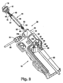
- a ground isolation connector 28, Figs 1-4, is provided for use with closure 10.
- connector 28 can be mounted in one of the preformed cable ports 26, if available, or on an external surface of wall 12.
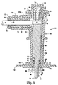
- Connector 28 includes a main housing 30, Fig. 2, having a first portion 32 and a second portion 34.
- First portion 32 includes a spool shaped outer surface 32a which is provided to nest into cable port 26.
- Second portion 34 includes an external ground wire port 34a formed therewith.
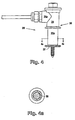
- Main housing 30 also includes a keyed bore 36 formed therethrough, Fig. 4a. Bore 36 is keyed with a hexagonal, cross-sectional shape, however, other cross-sectional shapes may be used.
- a threaded bore 38, Fig. 3, formed in port 34a extends to form an intersection with hex-shaped bore 36.
- An "O" ring groove 40 is provided in a flange 42 of second portion 34 adjacent ground wire port 34a for receiving a sealing "O" ring 41.
- a ground stud 44 includes a first end 46 and a second end 48.
- Second end 48, Fig. 3 includes an external threaded portion 49 and an internal threaded bore 50 which extends to intersect with an external ground wire cross-bore 52.
- First end 46 includes a threaded extension 54 which extends from a central shaft portion 56 having a hexagonally shaped cross-section, Fig. 2, for mating engagement within hex bore 36. In this manner, ground stud 44 is in anti-rotational engagement with hex bore 36.
- An "O" ring groove 58 is provided adjacent a land 60 between central shaft 56 and threaded extension 54 for receiving a sealing "O" ring 62.
- a cap screw 64 is threadably received in threaded bore 50 and seats to securely engage a stripped end 66 of an external ground wire 68.
- the ground wire 68 is retained in a commercially available liquid tight fitting 70 which has a threaded end 72 received into threaded bore 38 in port 34a.
- Fitting 70 includes a flexible sealing end 71 which grips ground wire 68.
- An end 77 is rotatable relative to end 71 on threaded shaft 73. The relative rotation urges a plurality of flexible fingers 75 and resilient sleeve 79 into sealing contact with wire 68.
- a housing cap 74 includes an internal threaded blind bore 76 which threadably engages threaded portion 49 of ground stud 44 and urges scaling "O" ring 41 into sealing engagement with groove 40.
- An internal ground wire 80 is attachable to threaded extension 54 by means of a connector 82 which receives extension 54.
- a washer 84 and a nut 86 engage extension 54 and draw "O" ring 62, Fig. 3, into sealing engagement between first portion 32 of housing 30 and groove 58 of ground stud 44.
- connector 28, Fig. 3 When cable ports 26 are occupied with cables, connector 28, Fig. 3, can be mounted on an external surface of wall 12 at mounting surface 18 with plug 20 removed to provide opening 21.
- Another "O" ring groove 92 is provided in a flange 94 of first portion 32. Groove 92 retains an “O” ring 96 for sealingly seating first portion 32 of housing 30 against mounting surface 18 of wall 12.
- a modified connector 28a has a reduced length housing 30a by disposing of the spool portion 32a, discussed above and illustrated in Figs. 2 and 3.
- Connector 28a also includes a reduced length ground stud 44a having a hex shaped portion 56a mated with a hex bore 36a. All other attributes of the connector and ground stud remain as described above.
- the purpose of the reduced length connector 28a is for applications where a reduced length connector is preferred for external connection directly to wall 12 only, whereas connector 28, illustrated in Figs. 1-4, can be either inserted into cable port 26, Figs. 1 and 2, or externally attached directly to wall 12, Fig. 3.
- stud 44 is inserted into connector 28.
- First end 46 extends from housing 30.
- Fitting 70 is threaded into port 34a.
- External ground wire 68 is inserted through fitting 70 and cross-bore 52.
- Fitting 70 is tightened to form a seal with wire 68.
- Cap screw 64 is adjusted to engage and maintain wire end 66 in bore 52.
- Housing cap 74 is sealingly threaded onto housing 30.
- Spool portion 32a is inserted into cable port 26 and sealed therein
- Nut 86 is adjusted to seal stud 44 to housing 30.
- Internal ground wire 80 is attached to extension 54 and secured thereto by nut 90.
- reduced length connector 28a is used with stud 44a.
- the "O" ring 96 is inserted in groove 92 and flange 94 is seated on mounting surface 18 of wall 12.
- Nut 86 is adjusted to compress "O" rings 96 and 62 and seal stud 44a and housing 30a to mounting surface 18 externally of wall 12.
- Internal ground wire 80 is attached to extension 54 and secured thereto by nut 90.
- the principal advantage of these embodiments is that the external ground isolation connector permits a sealed connection of the internal and external ground wires through the wall of a cable closure, or through a cable port of a cable closure, and allows for disconnection and reconnection of the wires in a manner which maintains seal integrity.
Landscapes
- Cable Accessories (AREA)
- Installation Of Indoor Wiring (AREA)
- Connector Housings Or Holding Contact Members (AREA)
Claims (10)
- Connecteur externe d'isolation de la terre' comprenant :un boítier (30) comprenant un alésage claveté (36) formé à travers celui-ci ;un goujon de mise à la terre (44, 44a) claveté adapté pour se prolonger à travers l'alésage (36) dans le boítier (30) de façon à limiter la rotation du goujon (44, 44a) à l'intérieur du boítier (30), le goujon de mise à la terre (44, 44a) ayant une première extrémité (46) adaptée pour se prolonger à l'intérieur d'un dispositif de fermeture de câble associé (10), et ayant une seconde extrémité (48) adaptée pour se prolonger à l'extérieur du dispositif de fermeture de câble (10) ;le boítier (30) comprenant un port (34a) formé à l'intérieur de celui-ci pour recevoir un fil externe de mise à la terre (68) à l'intérieur de celui-ci ;des moyens adjacents à la seconde extrémité (48) du goujon de mise à la terre (44, 44a) adaptés pour recevoir le fil externe de mise à la terre (68) ;des moyens adaptés pour relier un fil interne de mise à la terre (80) à la première extrémité (46) du goujon de mise à la terre (44, 44a) ;des moyens adaptés pour sceller le boítier (30) au dispositif de fermeture de câble (10) ; etdes moyens adaptés pour sceller le goujon de mise à la terre (44, 44a) à l'intérieur du boítier (30).
- Connecteur selon la revendication 1 dans lequel une première partie (32) du boítier (30) présente une surface externe de la forme d'un tiroir (32a).
- Connecteur selon la revendication 1 ou 2 dans lequel les moyens adaptés pour sceller le boítier (30) au dispositif de fermeture de câble (10) associé, comprennent une surface de boítier externe de la forme d'un tiroir (32a) adaptée pour s'engager par appariement avec un port de câble (26) formé dans le dispositif de fermeture associé (10).
- Connecteur selon l'une quelconque des revendications 1 à 3 dans lequel les moyens adaptés pour sceller le goujon de mise à la terre (44, 44a) à l'intérieur du boítier (30) comprennent des joints (41, 62) adjacents aux côtés opposés du boítier (30).
- Connecteur selon l'une quelconque des revendications 1 à 4 dans lequel le goujon de mise à la terre (44, 44a) comprend un alésage (52) pour recevoir un fil de mise à la terre formé à l'intérieur de celui-ci et une vis à tête (74) adaptée pour se prolonger dans l'alésage (52) pour recevoir le fil de mise à la terre de façon à engager et à maintenir un fil de mise à la terre (69) à l'intérieur de celui-ci.
- Connecteur selon l'une quelconque des revendications 1 à 5 comprenant en outre un capuchon (74) adapté pour permettre un engagement fileté avec le goujon de mise à la terre (44, 44a) et pour permettre un engagement étanche avec le boítier (30).
- Connecteur selon l'une quelconque des revendications 1 à 6 dans lequel la première extrémité (46) du goujon de mise à la terre (44, 44a) comprend une partie qui s'engage de façon étanche avec le boítier (30).
- Connecteur selon l'une quelconque des revendications 1 à 7 comprenant en outre un capuchon (74) adapté pour permettre un engagement étanche avec le boítier (30), des moyens pour maintenir le fil externe de mise à la terre (68) en position d'engagement avec la seconde extrémité (48) du goujon de mise à la terre (44, 44a) et des moyens pour maintenir le fil interne de misé à la terre connecté à la première extrémité (46) du goujon de mise à la terre (44, 44a).
- Connecteur selon l'une quelconque des revendications 1 à 8 dans lequel le port (34a) est adapté pour recevoir un branchement étanche du fil de mise à la terre (70).
- Procédé de connexion étanche d'un fil externe de mise à la terre (68) à un dispositif de fermeture de câble (10) comprenant les étapes consistant à :procurer un boítier (30) pour un connecteur d'isolation de la terre présentant un alésage claveté (36) formé à travers celui-ci et un port (34a) pour un fil externe de mise à la terre ;insérer un goujon de mise à la terre (44, 44a), claveté pour s'engager par appariement de façon anti-rotationnelle dans l'alésage claveté (36) ;insérer de façon étanche un fil externe de mise à la terre (68) dans le port (34a) ;fixer le fil externe de mise à la terre (68) à l'une des extrémités du goujon de mise à la terre (44, 44a) ;relier l'autre extrémité du goujon de mise à la terre (44, 44a) à un fil interne de mise à la terre (80) ;sceller la première extrémité du goujon de mise à la terre (44, 44a) à une première extrémité du boítier (30) ;fixer de façon étanche une première extrémité du boítier (30) au dispositif de fermeture de câble (10) ; etfixer un capuchon (74) afin de sceller une seconde extrémité du boítier (30).
Applications Claiming Priority (3)
| Application Number | Priority Date | Filing Date | Title |
|---|---|---|---|
| US08/821,974 US5842891A (en) | 1997-03-18 | 1997-03-18 | External ground isolation connector for cable splice closures |
| PCT/US1997/012913 WO1998042047A1 (fr) | 1997-03-18 | 1997-07-23 | Connecteur externe isolant pour mise a la terre de gaines d'epissure de cable |
| US821974 | 2001-03-30 |
Publications (2)
| Publication Number | Publication Date |
|---|---|
| EP0970546A1 EP0970546A1 (fr) | 2000-01-12 |
| EP0970546B1 true EP0970546B1 (fr) | 2002-10-02 |
Family
ID=25234757
Family Applications (1)
| Application Number | Title | Priority Date | Filing Date |
|---|---|---|---|
| EP97935084A Expired - Lifetime EP0970546B1 (fr) | 1997-03-18 | 1997-07-23 | Connecteur externe d'isolation de la terre pour des dispositifs de fermeture d'epissure de cable |
Country Status (14)
| Country | Link |
|---|---|
| US (1) | US5842891A (fr) |
| EP (1) | EP0970546B1 (fr) |
| JP (1) | JP2001515697A (fr) |
| KR (1) | KR20000076339A (fr) |
| CN (1) | CN1116715C (fr) |
| AU (1) | AU730954B2 (fr) |
| CA (1) | CA2281883A1 (fr) |
| DE (1) | DE69716138T2 (fr) |
| ES (1) | ES2185036T3 (fr) |
| IL (1) | IL131431A0 (fr) |
| MY (1) | MY133871A (fr) |
| TW (1) | TW365708B (fr) |
| WO (1) | WO1998042047A1 (fr) |
| ZA (1) | ZA981485B (fr) |
Families Citing this family (9)
| Publication number | Priority date | Publication date | Assignee | Title |
|---|---|---|---|---|
| US6655989B1 (en) * | 2002-07-10 | 2003-12-02 | Ford Motor Company | Environmentally sealed electrical connector system |
| US7492996B2 (en) | 2005-06-21 | 2009-02-17 | Adc Telecommunications, Inc. | Grounding device for armored cable |
| US7284994B2 (en) | 2005-06-21 | 2007-10-23 | Adc Telecommunications, Inc. | Grounding lug for armored cable and method |
| US7632160B2 (en) * | 2007-02-06 | 2009-12-15 | Na Communications, Llc | Four-way ground lug |
| EP2003757A1 (fr) * | 2007-06-15 | 2008-12-17 | Hauff-Technik GmbH & Co. KG | Traversée de paroi pour fil de terre |
| US8227696B2 (en) * | 2008-11-18 | 2012-07-24 | Tyco Electronics Corporation | Sealant-filled enclosures and methods for environmentally protecting a connection |
| WO2017114935A1 (fr) * | 2015-12-30 | 2017-07-06 | CommScope Connectivity Belgium BVBA | Logement à tige de masse à orientation automatique |
| CN107863842A (zh) * | 2017-12-12 | 2018-03-30 | 山东元清机电科技有限公司 | 一种电机接线结构 |
| US11190001B2 (en) * | 2019-09-26 | 2021-11-30 | Eaton Intelligent Power Limited | Cover assembly for a grounding arrangement |
Family Cites Families (9)
| Publication number | Priority date | Publication date | Assignee | Title |
|---|---|---|---|---|
| US2897472A (en) * | 1958-06-18 | 1959-07-28 | William M O'brien | Auxiliary terminal seal |
| DE3233572C2 (de) * | 1982-09-10 | 1986-01-09 | Felten & Guilleaume Energietechnik GmbH, 5000 Köln | Einphasige Endverschluß-Steckverbindung zum Verbinden eines Kabelleiters mit einem Schaltgerät, insbesondere mit einer SF↓6↓-Schaltanlage |
| EP0147979B1 (fr) * | 1983-12-14 | 1990-05-23 | Raychem Limited | Connecteur haute tension |
| US4799895A (en) * | 1987-06-22 | 1989-01-24 | Amerace Corporation | 600-Amp hot stick operable screw-assembled connector system |
| US5318459A (en) * | 1992-03-18 | 1994-06-07 | Shields Winston E | Ruggedized, sealed quick disconnect electrical coupler |
| GB2270209B (en) * | 1992-08-24 | 1996-02-07 | Cliff Electron Components Ltd | An electrical terminal |
| US5248265A (en) * | 1992-11-30 | 1993-09-28 | The Whitaker Corporation | Sealable electrical interconnection assembly |
| DE19502062A1 (de) * | 1995-01-13 | 1996-07-18 | Siemens Ag | Kontaktführungsstück für gekapselte Mittelspannungs-Schaltanlagen |
| US5639268A (en) * | 1995-11-24 | 1997-06-17 | Julian Electric, Inc. | Through the wall connector |
-
1997
- 1997-03-18 US US08/821,974 patent/US5842891A/en not_active Expired - Lifetime
- 1997-07-23 EP EP97935084A patent/EP0970546B1/fr not_active Expired - Lifetime
- 1997-07-23 ES ES97935084T patent/ES2185036T3/es not_active Expired - Lifetime
- 1997-07-23 IL IL13143197A patent/IL131431A0/xx unknown
- 1997-07-23 AU AU38108/97A patent/AU730954B2/en not_active Ceased
- 1997-07-23 KR KR1019997008440A patent/KR20000076339A/ko not_active Application Discontinuation
- 1997-07-23 DE DE69716138T patent/DE69716138T2/de not_active Expired - Lifetime
- 1997-07-23 CA CA002281883A patent/CA2281883A1/fr not_active Abandoned
- 1997-07-23 WO PCT/US1997/012913 patent/WO1998042047A1/fr active IP Right Grant
- 1997-07-23 CN CN97182036A patent/CN1116715C/zh not_active Expired - Fee Related
- 1997-07-23 JP JP54046798A patent/JP2001515697A/ja active Pending
-
1998
- 1998-02-17 TW TW087102144A patent/TW365708B/zh not_active IP Right Cessation
- 1998-02-23 ZA ZA9801485A patent/ZA981485B/xx unknown
- 1998-03-09 MY MYPI98001020A patent/MY133871A/en unknown
Also Published As
| Publication number | Publication date |
|---|---|
| DE69716138D1 (de) | 2002-11-07 |
| IL131431A0 (en) | 2001-01-28 |
| CN1116715C (zh) | 2003-07-30 |
| US5842891A (en) | 1998-12-01 |
| AU730954B2 (en) | 2001-03-22 |
| WO1998042047A1 (fr) | 1998-09-24 |
| CN1249074A (zh) | 2000-03-29 |
| JP2001515697A (ja) | 2001-09-18 |
| MY133871A (en) | 2007-11-30 |
| TW365708B (en) | 1999-08-01 |
| CA2281883A1 (fr) | 1998-09-24 |
| DE69716138T2 (de) | 2003-06-05 |
| KR20000076339A (ko) | 2000-12-26 |
| AU3810897A (en) | 1998-10-12 |
| ZA981485B (en) | 1999-08-23 |
| ES2185036T3 (es) | 2003-04-16 |
| EP0970546A1 (fr) | 2000-01-12 |
Similar Documents
| Publication | Publication Date | Title |
|---|---|---|
| CA2571472C (fr) | Ensemble d'etancheite avec ecrou pour connecteur coaxial | |
| EP0265276B1 (fr) | Joint anti humidité pour connecteur coaxial | |
| CA2121009C (fr) | Adapteur de raccordement male hermetique | |
| US5877452A (en) | Coaxial cable connector | |
| US5621191A (en) | Cable gland | |
| RU2383977C2 (ru) | Устройство концевой заделки кабеля, компонент кабельной системы и корпус фильтра | |
| US6881901B2 (en) | Connection cover | |
| US7207820B1 (en) | Connecting assembly for a cable and method of connecting a cable | |
| US7566831B2 (en) | Coaxial cable connector with internal pressure seal | |
| US20180076563A1 (en) | Connector seal device | |
| WO1998043320A1 (fr) | Connecteur de cable coaxial hermetique | |
| EP0970546B1 (fr) | Connecteur externe d'isolation de la terre pour des dispositifs de fermeture d'epissure de cable | |
| US20230086292A1 (en) | Couplings and connectors for cables | |
| EP0778438B1 (fr) | Moyeu avec joint d'étanchéité en élastomère résistant à la corrosion | |
| JPH11336961A (ja) | シールコネクタ | |
| EP3454424A1 (fr) | Connecteur de câble et couvercle | |
| MXPA99008405A (en) | External ground isolation connector for cable splice closures | |
| RU2174274C2 (ru) | Соединитель с внешней развязкой по земляной цепи для кожухов кабельных сростков | |
| JPH05300635A (ja) | 高圧大電力送電線の端末処理装置 |
Legal Events
| Date | Code | Title | Description |
|---|---|---|---|
| PUAI | Public reference made under article 153(3) epc to a published international application that has entered the european phase |
Free format text: ORIGINAL CODE: 0009012 |
|
| 17P | Request for examination filed |
Effective date: 19990914 |
|
| AK | Designated contracting states |
Kind code of ref document: A1 Designated state(s): CH DE FR GB IT LI Kind code of ref document: A1 Designated state(s): CH DE ES FR GB IT LI |
|
| 17Q | First examination report despatched |
Effective date: 20010601 |
|
| GRAG | Despatch of communication of intention to grant |
Free format text: ORIGINAL CODE: EPIDOS AGRA |
|
| GRAG | Despatch of communication of intention to grant |
Free format text: ORIGINAL CODE: EPIDOS AGRA |
|
| GRAH | Despatch of communication of intention to grant a patent |
Free format text: ORIGINAL CODE: EPIDOS IGRA |
|
| RBV | Designated contracting states (corrected) |
Designated state(s): CH DE ES FR GB IT LI |
|
| GRAH | Despatch of communication of intention to grant a patent |
Free format text: ORIGINAL CODE: EPIDOS IGRA |
|
| GRAA | (expected) grant |
Free format text: ORIGINAL CODE: 0009210 |
|
| AK | Designated contracting states |
Kind code of ref document: B1 Designated state(s): CH DE ES FR GB IT LI |
|
| PG25 | Lapsed in a contracting state [announced via postgrant information from national office to epo] |
Ref country code: LI Free format text: LAPSE BECAUSE OF FAILURE TO SUBMIT A TRANSLATION OF THE DESCRIPTION OR TO PAY THE FEE WITHIN THE PRESCRIBED TIME-LIMIT Effective date: 20021002 Ref country code: CH Free format text: LAPSE BECAUSE OF FAILURE TO SUBMIT A TRANSLATION OF THE DESCRIPTION OR TO PAY THE FEE WITHIN THE PRESCRIBED TIME-LIMIT Effective date: 20021002 |
|
| REG | Reference to a national code |
Ref country code: GB Ref legal event code: FG4D |
|
| REG | Reference to a national code |
Ref country code: CH Ref legal event code: EP |
|
| REF | Corresponds to: |
Ref document number: 69716138 Country of ref document: DE Date of ref document: 20021107 |
|
| ET | Fr: translation filed | ||
| REG | Reference to a national code |
Ref country code: ES Ref legal event code: FG2A Ref document number: 2185036 Country of ref document: ES Kind code of ref document: T3 |
|
| REG | Reference to a national code |
Ref country code: CH Ref legal event code: PL |
|
| PG25 | Lapsed in a contracting state [announced via postgrant information from national office to epo] |
Ref country code: GB Free format text: LAPSE BECAUSE OF NON-PAYMENT OF DUE FEES Effective date: 20030723 |
|
| PLBE | No opposition filed within time limit |
Free format text: ORIGINAL CODE: 0009261 |
|
| STAA | Information on the status of an ep patent application or granted ep patent |
Free format text: STATUS: NO OPPOSITION FILED WITHIN TIME LIMIT |
|
| 26N | No opposition filed |
Effective date: 20030703 |
|
| GBPC | Gb: european patent ceased through non-payment of renewal fee |
Effective date: 20030723 |
|
| PGFP | Annual fee paid to national office [announced via postgrant information from national office to epo] |
Ref country code: IT Payment date: 20070727 Year of fee payment: 11 |
|
| PG25 | Lapsed in a contracting state [announced via postgrant information from national office to epo] |
Ref country code: IT Free format text: LAPSE BECAUSE OF NON-PAYMENT OF DUE FEES Effective date: 20080723 |
|
| PGFP | Annual fee paid to national office [announced via postgrant information from national office to epo] |
Ref country code: ES Payment date: 20100813 Year of fee payment: 14 |
|
| PGFP | Annual fee paid to national office [announced via postgrant information from national office to epo] |
Ref country code: FR Payment date: 20100805 Year of fee payment: 14 Ref country code: DE Payment date: 20100721 Year of fee payment: 14 |
|
| REG | Reference to a national code |
Ref country code: FR Ref legal event code: ST Effective date: 20120330 |
|
| PG25 | Lapsed in a contracting state [announced via postgrant information from national office to epo] |
Ref country code: DE Free format text: LAPSE BECAUSE OF NON-PAYMENT OF DUE FEES Effective date: 20120201 Ref country code: FR Free format text: LAPSE BECAUSE OF NON-PAYMENT OF DUE FEES Effective date: 20110801 |
|
| REG | Reference to a national code |
Ref country code: DE Ref legal event code: R119 Ref document number: 69716138 Country of ref document: DE Effective date: 20120201 |
|
| REG | Reference to a national code |
Ref country code: ES Ref legal event code: FD2A Effective date: 20130605 |
|
| PG25 | Lapsed in a contracting state [announced via postgrant information from national office to epo] |
Ref country code: ES Free format text: LAPSE BECAUSE OF NON-PAYMENT OF DUE FEES Effective date: 20110724 |