EP0969888B1 - Verbesserte verbindung für fluidwege von scherkraftempfindlichen biologischen flüssigkeiten - Google Patents
Verbesserte verbindung für fluidwege von scherkraftempfindlichen biologischen flüssigkeiten Download PDFInfo
- Publication number
- EP0969888B1 EP0969888B1 EP98907418A EP98907418A EP0969888B1 EP 0969888 B1 EP0969888 B1 EP 0969888B1 EP 98907418 A EP98907418 A EP 98907418A EP 98907418 A EP98907418 A EP 98907418A EP 0969888 B1 EP0969888 B1 EP 0969888B1
- Authority
- EP
- European Patent Office
- Prior art keywords
- fluid
- cutwater
- blood
- fluid paths
- path
- Prior art date
- Legal status (The legal status is an assumption and is not a legal conclusion. Google has not performed a legal analysis and makes no representation as to the accuracy of the status listed.)
- Expired - Lifetime
Links
Images



Classifications
-
- A—HUMAN NECESSITIES
- A61—MEDICAL OR VETERINARY SCIENCE; HYGIENE
- A61M—DEVICES FOR INTRODUCING MEDIA INTO, OR ONTO, THE BODY; DEVICES FOR TRANSDUCING BODY MEDIA OR FOR TAKING MEDIA FROM THE BODY; DEVICES FOR PRODUCING OR ENDING SLEEP OR STUPOR
- A61M39/00—Tubes, tube connectors, tube couplings, valves, access sites or the like, specially adapted for medical use
- A61M39/10—Tube connectors; Tube couplings
-
- A—HUMAN NECESSITIES
- A61—MEDICAL OR VETERINARY SCIENCE; HYGIENE
- A61M—DEVICES FOR INTRODUCING MEDIA INTO, OR ONTO, THE BODY; DEVICES FOR TRANSDUCING BODY MEDIA OR FOR TAKING MEDIA FROM THE BODY; DEVICES FOR PRODUCING OR ENDING SLEEP OR STUPOR
- A61M60/00—Blood pumps; Devices for mechanical circulatory actuation; Balloon pumps for circulatory assistance
- A61M60/10—Location thereof with respect to the patient's body
- A61M60/104—Extracorporeal pumps, i.e. the blood being pumped outside the patient's body
- A61M60/109—Extracorporeal pumps, i.e. the blood being pumped outside the patient's body incorporated within extracorporeal blood circuits or systems
- A61M60/113—Extracorporeal pumps, i.e. the blood being pumped outside the patient's body incorporated within extracorporeal blood circuits or systems in other functional devices, e.g. dialysers or heart-lung machines
-
- A—HUMAN NECESSITIES
- A61—MEDICAL OR VETERINARY SCIENCE; HYGIENE
- A61M—DEVICES FOR INTRODUCING MEDIA INTO, OR ONTO, THE BODY; DEVICES FOR TRANSDUCING BODY MEDIA OR FOR TAKING MEDIA FROM THE BODY; DEVICES FOR PRODUCING OR ENDING SLEEP OR STUPOR
- A61M60/00—Blood pumps; Devices for mechanical circulatory actuation; Balloon pumps for circulatory assistance
- A61M60/20—Type thereof
- A61M60/205—Non-positive displacement blood pumps
- A61M60/216—Non-positive displacement blood pumps including a rotating member acting on the blood, e.g. impeller
- A61M60/226—Non-positive displacement blood pumps including a rotating member acting on the blood, e.g. impeller the blood flow through the rotating member having mainly radial components
- A61M60/232—Centrifugal pumps
-
- A—HUMAN NECESSITIES
- A61—MEDICAL OR VETERINARY SCIENCE; HYGIENE
- A61M—DEVICES FOR INTRODUCING MEDIA INTO, OR ONTO, THE BODY; DEVICES FOR TRANSDUCING BODY MEDIA OR FOR TAKING MEDIA FROM THE BODY; DEVICES FOR PRODUCING OR ENDING SLEEP OR STUPOR
- A61M60/00—Blood pumps; Devices for mechanical circulatory actuation; Balloon pumps for circulatory assistance
- A61M60/30—Medical purposes thereof other than the enhancement of the cardiac output
- A61M60/36—Medical purposes thereof other than the enhancement of the cardiac output for specific blood treatment; for specific therapy
- A61M60/38—Blood oxygenation
-
- A—HUMAN NECESSITIES
- A61—MEDICAL OR VETERINARY SCIENCE; HYGIENE
- A61M—DEVICES FOR INTRODUCING MEDIA INTO, OR ONTO, THE BODY; DEVICES FOR TRANSDUCING BODY MEDIA OR FOR TAKING MEDIA FROM THE BODY; DEVICES FOR PRODUCING OR ENDING SLEEP OR STUPOR
- A61M60/00—Blood pumps; Devices for mechanical circulatory actuation; Balloon pumps for circulatory assistance
- A61M60/80—Constructional details other than related to driving
- A61M60/802—Constructional details other than related to driving of non-positive displacement blood pumps
- A61M60/81—Pump housings
- A61M60/814—Volutes
-
- F—MECHANICAL ENGINEERING; LIGHTING; HEATING; WEAPONS; BLASTING
- F04—POSITIVE - DISPLACEMENT MACHINES FOR LIQUIDS; PUMPS FOR LIQUIDS OR ELASTIC FLUIDS
- F04D—NON-POSITIVE-DISPLACEMENT PUMPS
- F04D29/00—Details, component parts, or accessories
- F04D29/40—Casings; Connections of working fluid
- F04D29/42—Casings; Connections of working fluid for radial or helico-centrifugal pumps
- F04D29/426—Casings; Connections of working fluid for radial or helico-centrifugal pumps especially adapted for liquid pumps
- F04D29/428—Discharge tongues
-
- A—HUMAN NECESSITIES
- A61—MEDICAL OR VETERINARY SCIENCE; HYGIENE
- A61M—DEVICES FOR INTRODUCING MEDIA INTO, OR ONTO, THE BODY; DEVICES FOR TRANSDUCING BODY MEDIA OR FOR TAKING MEDIA FROM THE BODY; DEVICES FOR PRODUCING OR ENDING SLEEP OR STUPOR
- A61M2202/00—Special media to be introduced, removed or treated
- A61M2202/04—Liquids
- A61M2202/0413—Blood
-
- A—HUMAN NECESSITIES
- A61—MEDICAL OR VETERINARY SCIENCE; HYGIENE
- A61M—DEVICES FOR INTRODUCING MEDIA INTO, OR ONTO, THE BODY; DEVICES FOR TRANSDUCING BODY MEDIA OR FOR TAKING MEDIA FROM THE BODY; DEVICES FOR PRODUCING OR ENDING SLEEP OR STUPOR
- A61M2206/00—Characteristics of a physical parameter; associated device therefor
- A61M2206/10—Flow characteristics
-
- Y—GENERAL TAGGING OF NEW TECHNOLOGICAL DEVELOPMENTS; GENERAL TAGGING OF CROSS-SECTIONAL TECHNOLOGIES SPANNING OVER SEVERAL SECTIONS OF THE IPC; TECHNICAL SUBJECTS COVERED BY FORMER USPC CROSS-REFERENCE ART COLLECTIONS [XRACs] AND DIGESTS
- Y10—TECHNICAL SUBJECTS COVERED BY FORMER USPC
- Y10S—TECHNICAL SUBJECTS COVERED BY FORMER USPC CROSS-REFERENCE ART COLLECTIONS [XRACs] AND DIGESTS
- Y10S415/00—Rotary kinetic fluid motors or pumps
- Y10S415/90—Rotary blood pump
-
- Y—GENERAL TAGGING OF NEW TECHNOLOGICAL DEVELOPMENTS; GENERAL TAGGING OF CROSS-SECTIONAL TECHNOLOGIES SPANNING OVER SEVERAL SECTIONS OF THE IPC; TECHNICAL SUBJECTS COVERED BY FORMER USPC CROSS-REFERENCE ART COLLECTIONS [XRACs] AND DIGESTS
- Y10—TECHNICAL SUBJECTS COVERED BY FORMER USPC
- Y10T—TECHNICAL SUBJECTS COVERED BY FORMER US CLASSIFICATION
- Y10T137/00—Fluid handling
- Y10T137/206—Flow affected by fluid contact, energy field or coanda effect [e.g., pure fluid device or system]
- Y10T137/2087—Means to cause rotational flow of fluid [e.g., vortex generator]
- Y10T137/2104—Vortex generator in interaction chamber of device
-
- Y—GENERAL TAGGING OF NEW TECHNOLOGICAL DEVELOPMENTS; GENERAL TAGGING OF CROSS-SECTIONAL TECHNOLOGIES SPANNING OVER SEVERAL SECTIONS OF THE IPC; TECHNICAL SUBJECTS COVERED BY FORMER USPC CROSS-REFERENCE ART COLLECTIONS [XRACs] AND DIGESTS
- Y10—TECHNICAL SUBJECTS COVERED BY FORMER USPC
- Y10T—TECHNICAL SUBJECTS COVERED BY FORMER US CLASSIFICATION
- Y10T137/00—Fluid handling
- Y10T137/206—Flow affected by fluid contact, energy field or coanda effect [e.g., pure fluid device or system]
- Y10T137/2087—Means to cause rotational flow of fluid [e.g., vortex generator]
- Y10T137/2109—By tangential input to axial output [e.g., vortex amplifier]
-
- Y—GENERAL TAGGING OF NEW TECHNOLOGICAL DEVELOPMENTS; GENERAL TAGGING OF CROSS-SECTIONAL TECHNOLOGIES SPANNING OVER SEVERAL SECTIONS OF THE IPC; TECHNICAL SUBJECTS COVERED BY FORMER USPC CROSS-REFERENCE ART COLLECTIONS [XRACs] AND DIGESTS
- Y10—TECHNICAL SUBJECTS COVERED BY FORMER USPC
- Y10T—TECHNICAL SUBJECTS COVERED BY FORMER US CLASSIFICATION
- Y10T137/00—Fluid handling
- Y10T137/206—Flow affected by fluid contact, energy field or coanda effect [e.g., pure fluid device or system]
- Y10T137/2087—Means to cause rotational flow of fluid [e.g., vortex generator]
- Y10T137/2109—By tangential input to axial output [e.g., vortex amplifier]
- Y10T137/2115—With means to vary input or output of device
Definitions
- Shear sensitive fluids including biological fluids such as blood and blood-based combinations, should not be exposed to sudden or extreme changes in pressure or temperature, impacts, vibration, or rapid changes in direction of flow. Nonturbulent flow is the preferred mode of handling shear sensitive fluids.
- WO 94/17304 discloses a blood pump with a disposable rotor assembly.
- a deflector is provided to prevent blood from being impelled more than once around the impeller chamber periphery.
- the invention provides a biological fluid transfer device for carrying biological shear sensitive fluids, comprising a cutwater at a junction of at least two fluid paths within the device; characterised in that said cutwater is vertical, whereby the vertical direction is perpendicular to the primary direction of fluid flow at the cutwater location, and/or straight in order to reduce shear forces in the vicinity of the cutwater.
- the junction is the location where a fluid path is split into two or more paths.
- the junction can be an outlet for fluid to leave a device or an inlet for fluid to enter a device.
- At least one of the fluid paths or circuits may be tubular, and in some embodiments all of the fluid paths or circuits are tubular.
- the shear sensitive fluid may be, without limitation, blood, blood-based combinations such as "platelet gel," cell culture media, cell suspensions, proteins, and microcapsule suspensions.
- the device may be part of an extracorporeal bypass circuit but it need not be.
- Preferred embodiments of the device include, without limitation, kinetic pumps, mass transfer devices, filters, reservoirs, heat exchangers, and blood processing systems (such as diagnostic hemostasis management systems and blood coagulation testing systems).
- a fluid path is any series of locations occupied by the fluid.
- a circuit is a path which forms at least a portion of a closed loop, such as would be established with a path from a source of fluid to a device, and another path from the device back to the source. Of course, multiple devices could be employed.
- fluid transport devices comprise housings and other components which present junctions at which the fluid may flow in more than one direction.
- such devices may comprise obstructions, interfaces, edges, and the like, somewhere along the path or circuit traveled by the fluid.
- junctions in fluid tubing and tubing-based accessories may also create undesirable shear stress in the fluids they carry. Examples of such junctions are in-line splitters and connectors which have more than one connection upstream and/or downstream of the flow path through the device; "Y" adapters and "T” adapters; manifolds, and the like.
- a common extracorporeal circuit includes devices such as kinetic pumps, mass transfer devices, filters, reservoirs, and heat exchangers. (Some of these components may be incorporated into the design of other of the components. For example, a mass transfer device may have an integral heat exchanger, reservoir, filter, or a combination of any or all of them.)
- the components may include bubble and membrane oxygenators, arterial filters, cardiotomy reservoirs, bubble separators, blood heat exchangers, and red blood cell washers.
- extracorporeal blood circuits Other types of blood management systems employ extracorporeal blood circuits.
- the invention is suitable for all of these devices, both when they are incorporated into an extracorporeal bypass circuit, and when such devices are used for biological shear sensitive fluids outside the context of extracorporeal bypass (e.g., blood in coagulation testing systems, cell culture media, cell suspensions, proteins, and microcapsule suspensions).
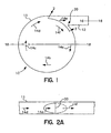
- Figure 1 is a cross sectional schematic view of a common feature in a generic device 10 which, for purposes of illustration only, is generally circular in cross section and has a housing 11 of negligible thickness.
- the device includes an outlet 12 that permits some or all of the fluid (not shown) to leave the housing when the fluid is traveling in the general direction indicated by flow arrows 14a-14d.
- the outlet 12 is commonly tubular (for reasons not critical to the invention) and called a "tangential outlet” since the axis of symmetry 16-16 of the outlet 12 does not generally coincide with a diameter 18-18 of the generally circular housing parallel to the flow through the tubular path 12.
- the tangential outlet 12 need not be located so that the flow path axis 16 is exactly tangential with the generally circular cross-sectional profile of the housing. A relatively small amount of offset toward or away from the axis of symmetry 18 of the housing 11 is possible.
- the outlet flow axis 16 and the housing diameter 18 are commonly parallel in the cross-sectional plane, but slight deviations on the order of one to thirty degrees are possible.
- the outlet flow axis 16 and the housing diameter 18 are commonly coplanar in the cross-sectional plane, even if not exactly parallel in that plane, but slight deviations on the order of one to thirty degrees are also possible.
- a common design technique is to introduce "draft,” i.e., small deviations in various dimensions and/or angles, to provide adequate clearance for a molded housing to be removed from its mold.
- draft i.e., small deviations in various dimensions and/or angles
- Such deviations are not necessarily reflected in the Figures or this description; however, incorporation of draft or other similar manufacturing techniques into a particular embodiment of the invention is preferred and not considered to be a departure from the scope of the invention.
- fluid flows along the general direction of the flow paths 14a, 14b, 14c and 14d. Fluid then either enters the outlet 12 by following flow path 14e, or remains within device 10 by following flow path 14f.
- fluid flow in the vicinity of the junction of the generally circular main portion of the housing 11 and the outlet 12 will be drawn or split, and thus experience shear stress, at or in the immediate vicinity of the junction of the main housing 11 and the outlet 12.
- This junction comprises an edge commonly known as cutwater 20.
- the rate of change of fluid velocity at the cutwater 20 is a source of shear stress in kinetic pumps.
- Figure 2A is a partial cross sectional view of the cutwater 20 showing together the straight and vertical edge characteristic of the invention, although the edge could be either straight or vertical.
- the vertical direction is substantially perpendicular to the primary direction of fluid flow at the cutwater location.
- the edge is designated "straight" or “vertical” to distinguish it from the conventional edge, indicated in phantom, which can appear straight and vertical when viewed directly in the plane of Figure 1.
- the conventional edge is shown in phantom as the half-elliptical shape that follows naturally if outlet 12 is a right circular cylinder, as it is conventionally, and intersects circular housing 11 along a generally tangential path.
- a "straight" cutwater or a “vertical” cutwater can have minor deviations from a perfectly straight and/or perfectly vertical linear edge, as long as those deviations are not significant on the scale of the vertical length (height) of the cutwater.
- the cutwater could be straight or linear from end to end, but slanted slightly from vertical as shown in Figures 2B and 2C.
- the invention is a device for carrying biological shear sensitive fluids, comprising a straight and/or vertical cutwater at a junction of at least two fluid paths or circuits within the device.
- the junction is the location where the fluid flow within a fluid path is split into two or more other paths.
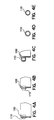
- FIGs 3 and 4A to 4E illustrate an embodiment of the invention for use on an otherwise conventional centrifugal blood pump.
- a device comprises a housing 100 having an inlet (not shown) for fluid (not shown) entering the housing 100, and a tangential outlet 110 for the fluid to exit the housing 100.
- a rotating impeller increases the angular velocity of the fluid, but the impeller design preferably minimizes shear stress on the fluid.
- the fluid Once the fluid reaches the junction between the housing and the tangential outlet, it is exposed to the cutwater as described above.
- An example of such a pump is the BioPump model BP-80 commercially available from Medtronic Bio-Medicus of Minneapolis, Minnesota, USA.
- Figure 4A shows a straight and vertical cutwater 120.
- Figure 4B shows that the cross sectional profile of fluid outlet 110 is substantially rectangular (neglecting slight deviations due to draft) at a location common to the volume of the main portion of housing 100 and outlet 110. This cross sectional profile gradually tapers, as seen from the sequential cross sectional views of Figures 4C and 4D.
- Figure 4E shows that the tapering does not continue to the end of the outlet where the fluid exits the pump; that is, the inner diameter of fluid outlet 110 is generally circular when viewed in cross section at fluid outlet 110.
- the cross sectional area of the outlet 110 at the exit of the pump ( Figure 4E) is preferably greater than the cross sectional area of the outlet 110 at the junction with the main portion of the housing 100. This is to accommodate the inner diameter of tubing typically connected to the pump at the outlet, but it is not necessary to the practice of the invention.
- cutwater 120 reduces shear stress due to its vertical and/or straight configuration alone, it is preferred to radius the edge. As shown in detail in Figure 4F, cutwater 120 has a radius of curvature in the horizontal plane of preferably 0.025 to 0.75 mm (0.001 to 0.030 inch), and most preferably at least 0.1 mm (0.004 inch). The choice of radius of curvature should take into account the clearance between the cutwater and the impeller.
- the housing 100 may be constructed according to conventional techniques from a variety of materials approved for contact with biological fluids, such as medical grade polycarbonates suitable for blood and blood-based mixtures.
- a preferred material is available from the Bayer Corporation or the General Polymers Division of the Ashland Corporation under the Bayer tradename MAKROLON, specifically type RX-2530-1118 (see http://www.ashchem.com/GP/data/-1373.htm).
- the surface finish on surfaces of the housing 100 which contact blood is preferably SPI/SPE No. 2. Rough surfaces, scratches, scuffs, nicks, cracks, etc. should be eliminated to reduce shear stress in the fluid.
- the inner surface can be coated with an antithrombogenic agent not essential to the invention.
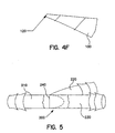
- Figure 5 shows a "2-way" connector 200 comprising a first fluid path 210 and second and third fluid paths 220 and 230.
- the first fluid path 210 can be an inlet to connector 200, with the second and third fluid paths 220 and 230 being outlets.
- a substantially straight and/or vertical cutwater 240 is shown in the cutaway portion at the junction of the three fluid paths circuits. Again, the conventional elliptical cutwater is shown in phantom.
- a mass transfer device such as a bubble or membrane oxygenator
- filters such as an arterial or cardiotomy filter
- reservoirs such as a blood or cardiotomy reservoir
- heat exchangers heat exchangers.
- the embodiment of Figure 5 is suitable for extracorporeal bypass circuit components, as well as components and circuits used for biological shear sensitive fluids outside the context of extracorporeal bypass (e.g., cell culture media, cell suspensions, proteins, and microcapsule suspensions).
- Application of the substantially straight or substantially vertical cutwater to "3-way" connectors, manifolds, and the like can easily be accomplished.
- the success of the invention is believed to be due to reduction of elevated shear forces in the vicinity of the cutwater created by a vortex set up by the flow over the cutwater surface.
- Fluid approaching a curved cutwater on the fluid outlet side follows a partially upward path as it crosses over the cutwater back to the main chamber of the device. This movement results in a mean rotational motion, that is, a vortex.
- Fluid upstream of the cutwater and on the bottom portion of the vortex, that would otherwise move to the main chamber of the device is forced to move to the fluid outlet side of the cutwater in a turbulent motion. Turbulent motion is undesirable since it creates rapidly changing velocity components that induce shear stress on the fluid.
- the inventive cutwater induces less shear stress because it reduces rate of change of velocity components on either side of the cutwater.
- the conventional geometry induces higher shear stress by generating higher levels of vorticity as compared to the invention. Vorticity is generated as the fluid passes the cutwater. These vortices create substantial changes in the magnitude and direction of the fluid (i.e. change in velocity components) over a given area.
- the inventive geometry reduces induced rotational forces on the fluid and consequently reduces the compression of the fluid path.
- the in-vitro hemolysis test measured blood trauma caused by the extracorporeal centrifugal pumps. Plasma free hemoglobin levels are measured and reported over a four hour test duration. Free hemoglobin generation rate (mg/dl/hour) is calculated. Hematocrit is adjusted at the start of the test and monitored throughout the four hour test duration.
- the test requires 1000cc of fresh bovine blood less than eight hours old.
- the blood is preferably washed and resuspended in saline, but this is not required.
- the blood plasma had an initial plasma free hemoglobin level less than 25 mg/dl.
- the blood did not "auto" hemolyze.
- the following test conditions were applied: Blood Flow Rate 4 liters/min ⁇ 5% Differential Pressure (P out -P in ) 53.2 kPa ⁇ 2.66 kPa (400 mm Hg ⁇ 20 mmHg) Temperature 37 C ⁇ 1 C Blood Volume 1000 cc ⁇ 100 cc Hematocrit 30% ⁇ 1% adjusted with saline solution
- the maximum plasma free hemoglobin increase of the control from the baseline sample should be 10 mg/dl (milligrams per deciliter). If the negative control does not meet this criteria, the test for the device hemolysis is rendered invalid. Each device is tested over four hours, flowing at 4 1/minute.
- Plasma free hemoglobin (mg/dL) is measured at time 0 and at 60 minute intervals. Hematocrit is measured at time 0. Hematocrit is typically not expected to change substantially in these in-vitro tests. Flow (Liters/min), temperature, and pressure are measured throughout the test.
- the test requires a kinetic pump, a pressure monitoring device, a flow probe, a temperature monitoring device, a microhematocrit centrifuge, a blood bank centrifuge, a sequence of pressure reducers, a spectral photometer, sodium chloride 0.9%, sterile, for adjusting hematocrit and anticoagulant.
- the design, number, and location of the pressure reducers are selected to minimize introduction of additional hemolysis. For example, a series of four inline reducers in the pump outlet line is preferred.
- the fluid handling circuit is a closed system, including the kinetic pump, a blood reservoir bag, 1.2 to 1.5 m (4 to 5 feet) of PVC tubing (9 mm (3/8 inch I.D.)) and plastic connectors. Hematocrit of the blood is adjusted to 30% by adding saline. Blood samples are drawn for blood trauma analysis according to the sampling plan.
- the absolute rate of hemolysis was measured for 48 samples of a kinetic pump using a housing having the configuration of Figures 3-4.
- the absolute hemolysis rates are listed in the second column of Table 1.
- the third column of Table 1 shows the ratio of the hemolysis rates of the pumps of Figures 3-4 to the comparative example, pumps having the cutwater identical to that of the commercially available BP-80 pump as described earlier/ . Entries of 1.00 indicate no change in hemolysis rate, with entries less than 1.00 indicating improvement and entries greater than 1.00 indicating degradation in performance. Sample number 1 was omitted from the data analysis.
Landscapes
- Health & Medical Sciences (AREA)
- Engineering & Computer Science (AREA)
- Heart & Thoracic Surgery (AREA)
- Cardiology (AREA)
- Animal Behavior & Ethology (AREA)
- Veterinary Medicine (AREA)
- Hematology (AREA)
- Life Sciences & Earth Sciences (AREA)
- Anesthesiology (AREA)
- General Health & Medical Sciences (AREA)
- Public Health (AREA)
- Biomedical Technology (AREA)
- Mechanical Engineering (AREA)
- Pulmonology (AREA)
- General Engineering & Computer Science (AREA)
- Emergency Medicine (AREA)
- External Artificial Organs (AREA)
- Infusion, Injection, And Reservoir Apparatuses (AREA)
Claims (9)
- Transportvorrichtung für biologische Fluide, die biologische scherempfindliche Fluide befördert und an einer Verbindungsstelle wenigstens zweier Fluidwege in der Vorrichtung einen Strömungsteiler (20) aufweist, dadurch gekennzeichnet, dass der Strömungsteiler vertikal ist, wodurch die vertikale Richtung zu der Hauptrichtung der Fluidströmung am Ort des Strömungsteilers (20) senkrecht ist, und/oder geradlinig ist, um die Scherkräfte in der Umgebung des Strömungsteilers (20) zu verringern.
- Vorrichtung nach Anspruch 1, bei der wenigstens einer der Fluidwege ein Auslass (12) für Fluid in wenigstens einem anderen Kreis ist.
- Vorrichtung nach Anspruch 1 oder 2, bei der wenigstens einer der Fluidwege ein Einlass für Fluid ist, so dass es in wenigstens einen anderen Weg eintritt bzw. eintreten kann.
- Vorrichtung nach einem der vorhergehenden Ansprüche, bei der wenigstens ein Fluidweg einen rohrförmigen Querschnitt hat.
- Vorrichtung nach einem der vorhergehenden Ansprüche, bei der das scherempfindliche Fluid ein Fluid umfasst, das aus der Gruppe gewählt ist, die im Wesentlichen aus Blut, Zellkulturmedien, Zellensuspensionen, Proteinen und Mikrokapsel-Suspensionen besteht.
- Vorrichtung nach einem der vorhergehenden Ansprüche, wobei die Vorrichtung ein Teil eines extrakorporalen Bypass-Kreises ist.
- Vorrichtung nach einem der vorhergehenden Ansprüche, wobei die Vorrichtung aus der Gruppe ausgewählt ist, die im Wesentlichen aus kinematischen Pumpen, Massenübertragungsvorrichtungen, Filtern, Vorratsbehältern und Wärmetauschern besteht.
- Vorrichtung nach einem der vorhergehenden Ansprüche, bei der wenigstens einer der Fluidwege konisch zuläuft oder sein Querschnittsprofil von einem rechtwinkligen Querschnittsprofil am Ende des Weges an der Verbindungsstelle zu einem kreisförmigen Querschnittsprofil ändert.
- Vorrichtung nach einem der Ansprüche 1 bis 7, bei dem das Querschnittsprofil keines der Fluidwege konisch zuläuft.
Applications Claiming Priority (3)
| Application Number | Priority Date | Filing Date | Title |
|---|---|---|---|
| US800904 | 1991-11-27 | ||
| US08/800,904 US5971023A (en) | 1997-02-12 | 1997-02-12 | Junction for shear sensitive biological fluid paths |
| PCT/US1998/002585 WO1998034658A1 (en) | 1997-02-12 | 1998-02-12 | Improved junction for shear sensitive biological fluid paths |
Publications (2)
| Publication Number | Publication Date |
|---|---|
| EP0969888A1 EP0969888A1 (de) | 2000-01-12 |
| EP0969888B1 true EP0969888B1 (de) | 2004-07-21 |
Family
ID=25179678
Family Applications (1)
| Application Number | Title | Priority Date | Filing Date |
|---|---|---|---|
| EP98907418A Expired - Lifetime EP0969888B1 (de) | 1997-02-12 | 1998-02-12 | Verbesserte verbindung für fluidwege von scherkraftempfindlichen biologischen flüssigkeiten |
Country Status (6)
| Country | Link |
|---|---|
| US (2) | US5971023A (de) |
| EP (1) | EP0969888B1 (de) |
| JP (1) | JP2001511670A (de) |
| CA (1) | CA2280702A1 (de) |
| DE (1) | DE69825151T2 (de) |
| WO (1) | WO1998034658A1 (de) |
Families Citing this family (29)
| Publication number | Priority date | Publication date | Assignee | Title |
|---|---|---|---|---|
| BG63583B1 (bg) * | 2000-04-12 | 2002-05-31 | СОРОЧИНСКИ Александр | Метод за торсионно въздействие на работни среди иторсионен генератор, реализиращ метода |
| US20070181836A1 (en) * | 2006-01-24 | 2007-08-09 | Axxiom Manufactuing, Inc. | Ergonomic pneumatic deadman valve |
| JP6134702B2 (ja) | 2012-03-23 | 2017-05-24 | テルモ株式会社 | 遠心ポンプおよび遠心ポンプの製造方法 |
| US9511178B2 (en) | 2012-07-09 | 2016-12-06 | Medtronic, Inc. | Reducing centrifugal pump bearing wear through dynamic magnetic coupling |
| WO2014074204A1 (en) * | 2012-11-10 | 2014-05-15 | Carrier Corporation | Centrifugal pump with slanted cutwater for cavitation prevention |
| JP6051056B2 (ja) | 2013-01-15 | 2016-12-21 | 株式会社荏原製作所 | 渦巻ポンプ |
| WO2015175711A1 (en) | 2014-05-13 | 2015-11-19 | Abiomed, Inc. | Blood pump housing component |
| AU2017205172B2 (en) | 2016-01-06 | 2022-02-10 | Bivacor Inc. | Heart pump |
| US9897121B1 (en) * | 2016-09-28 | 2018-02-20 | Atieva, Inc. | Automotive air intake utilizing a vortex generating airflow system |
| WO2018187576A2 (en) | 2017-04-05 | 2018-10-11 | Bivacor Inc. | Heart pump drive and bearing |
| DE102018201030B4 (de) | 2018-01-24 | 2025-10-16 | Kardion Gmbh | Magnetkuppelelement mit magnetischer Lagerungsfunktion |
| DE102018207611A1 (de) | 2018-05-16 | 2019-11-21 | Kardion Gmbh | Rotorlagerungssystem |
| DE102018207594A1 (de) | 2018-05-16 | 2019-11-21 | Kardion Gmbh | Rotor, Magnetkupplungsvorrichtung, Elektromotor für ein Herzunterstützungssystem, Pumpeneinheit für ein Herzunterstützungssystem sowie Verfahren zum Herstellen eines Rotors |
| DE102018207575A1 (de) | 2018-05-16 | 2019-11-21 | Kardion Gmbh | Magnetische Stirndreh-Kupplung zur Übertragung von Drehmomenten |
| DE102018208549A1 (de) | 2018-05-30 | 2019-12-05 | Kardion Gmbh | Elektronikmodul für ein Herzunterstützungssystem und Verfahren zum Herstellen eines Elektronikmoduls für ein Herzunterstützungssystem |
| DE102018208550A1 (de) | 2018-05-30 | 2019-12-05 | Kardion Gmbh | Leitungsvorrichtung zum Leiten eines Blutstroms für ein Herzunterstützungssystem, Herzunterstützungssystem und Verfahren zum Herstellen einer Leitungsvorrichtung |
| DE102018208539A1 (de) | 2018-05-30 | 2019-12-05 | Kardion Gmbh | Motorgehäusemodul zum Abdichten eines Motorraums eines Motors eines Herzunterstützungssystems und Herzunterstützungssystem und Verfahren zum Montieren eines Herzunterstützungssystems |
| DE102018208538A1 (de) | 2018-05-30 | 2019-12-05 | Kardion Gmbh | Intravasale Blutpumpe und Verfahren zur Herstellung von elektrischen Leiterbahnen |
| DE102018208541A1 (de) | 2018-05-30 | 2019-12-05 | Kardion Gmbh | Axialpumpe für ein Herzunterstützungssystem und Verfahren zum Herstellen einer Axialpumpe für ein Herzunterstützungssystem |
| DE102018210076A1 (de) | 2018-06-21 | 2019-12-24 | Kardion Gmbh | Verfahren und Vorrichtung zum Erkennen eines Verschleißzustands eines Herzunterstützungssystems, Verfahren und Vorrichtung zum Betreiben eines Herzunterstützungssystems und Herzunterstützungssystem |
| DE102018210058A1 (de) | 2018-06-21 | 2019-12-24 | Kardion Gmbh | Statorschaufelvorrichtung zur Strömungsführung eines aus einer Austrittsöffnung eines Herzunterstützungssystems ausströmenden Fluids, Herzunterstützungssystem mit Statorschaufelvorrichtung, Verfahren zum Betreiben einer Statorschaufelvorrichtung und Herstellverfahren |
| DE102018211297A1 (de) | 2018-07-09 | 2020-01-09 | Kardion Gmbh | Herzunterstützungssystem und Verfahren zur Überwachung der Integrität einer Haltestruktur eines Herzunterstützungssystems |
| DE102018211327A1 (de) | 2018-07-10 | 2020-01-16 | Kardion Gmbh | Laufrad für ein implantierbares, vaskuläres Unterstützungssystem |
| DE102018211328A1 (de) | 2018-07-10 | 2020-01-16 | Kardion Gmbh | Laufradgehäuse für ein implantierbares, vaskuläres Unterstützungssystem |
| DE102018212153A1 (de) | 2018-07-20 | 2020-01-23 | Kardion Gmbh | Zulaufleitung für eine Pumpeneinheit eines Herzunterstützungssystems, Herzunterstützungssystem und Verfahren zum Herstellen einer Zulaufleitung für eine Pumpeneinheit eines Herzunterstützungssystems |
| ES3055124T3 (en) | 2018-08-07 | 2026-02-10 | Kardion Gmbh | Bearing device for a heart support system, and method for rinsing a space in a bearing device for a heart support system |
| DE102020102474A1 (de) | 2020-01-31 | 2021-08-05 | Kardion Gmbh | Pumpe zum Fördern eines Fluids und Verfahren zum Herstellen einer Pumpe |
| JP7744043B2 (ja) | 2020-09-14 | 2025-09-25 | カルディオン ゲーエムベーハー | 可変流れ領域を備えたインペラを有する心血管補助ポンプ |
| US12589237B2 (en) | 2020-11-20 | 2026-03-31 | Kardion Gmbh | Mechanical circulatory support system with guidewire aid |
Family Cites Families (22)
| Publication number | Priority date | Publication date | Assignee | Title |
|---|---|---|---|---|
| US2144417A (en) * | 1937-01-11 | 1939-01-17 | Claude B Schneible | Sludge pump |
| US2291478A (en) * | 1939-08-12 | 1942-07-28 | Bour Harry E La | Centrifugal pump |
| US3461897A (en) * | 1965-12-17 | 1969-08-19 | Aviat Electric Ltd | Vortex vent fluid diode |
| US3322070A (en) * | 1966-03-11 | 1967-05-30 | Allis Chalmers Mfg Co | Vortex pump |
| US3957389A (en) * | 1967-10-26 | 1976-05-18 | Bio-Medicus, Inc. | Pumping apparatus and process characterized by gentle operation |
| US3864055A (en) * | 1971-12-06 | 1975-02-04 | Harold D Kletschka | Pumps capable of use as heart pumps and blood pumps |
| DE2643594A1 (de) * | 1975-10-06 | 1977-04-14 | Roger Beelen | Haemodialyse-nadel |
| US4403911A (en) * | 1977-12-08 | 1983-09-13 | Possell Clarence R | Bladeless pump and method of using same |
| US4213752A (en) * | 1978-11-06 | 1980-07-22 | Suntech, Inc. | Coal drying process |
| US4259988A (en) * | 1979-09-17 | 1981-04-07 | Avco Everett Research Laboratory, Inc. | Vortex-diode check valve with flexible diaphragm |
| CA1222903A (en) * | 1983-04-15 | 1987-06-16 | Jules L. Dussourd | Pump volute communicating slot for stability |
| US5127800A (en) * | 1984-03-20 | 1992-07-07 | Baker Hughes Incorporated | Flow-stabilizing volute pump and liner |
| US4917571A (en) * | 1984-03-20 | 1990-04-17 | John Hyll | Flow-stabilizing volute pump and liner |
| NZ211792A (en) * | 1984-04-18 | 1986-09-10 | Warman Int Ltd | Centrifugal pump casing |
| US4585435A (en) * | 1984-05-31 | 1986-04-29 | The Telescope Folding Furniture Co., Inc. | Extension set for drug delivery |
| US4789301A (en) * | 1986-03-27 | 1988-12-06 | Goulds Pumps, Incorporated | Low specific speed pump casing construction |
| US4872809A (en) * | 1987-03-06 | 1989-10-10 | Giw Industries, Inc. | Slurry pump having increased efficiency and wear characteristics |
| JPH03117699A (ja) * | 1989-09-30 | 1991-05-20 | Ube Ind Ltd | モーター体型歳差式遠心ポンプ |
| US5129264A (en) * | 1990-12-07 | 1992-07-14 | Goulds Pumps, Incorporated | Centrifugal pump with flow measurement |
| US5080137A (en) * | 1990-12-07 | 1992-01-14 | Adams Thomas R | Vortex flow regulators for storm sewer catch basins |
| US5266003A (en) * | 1992-05-20 | 1993-11-30 | Praxair Technology, Inc. | Compressor collector with nonuniform cross section |
| US5393207A (en) * | 1993-01-21 | 1995-02-28 | Nimbus, Inc. | Blood pump with disposable rotor assembly |
-
1997
- 1997-02-12 US US08/800,904 patent/US5971023A/en not_active Expired - Lifetime
-
1998
- 1998-02-12 EP EP98907418A patent/EP0969888B1/de not_active Expired - Lifetime
- 1998-02-12 CA CA 2280702 patent/CA2280702A1/en not_active Abandoned
- 1998-02-12 WO PCT/US1998/002585 patent/WO1998034658A1/en not_active Ceased
- 1998-02-12 JP JP53502298A patent/JP2001511670A/ja not_active Ceased
- 1998-02-12 DE DE1998625151 patent/DE69825151T2/de not_active Expired - Fee Related
-
1999
- 1999-03-09 US US09/266,408 patent/US6293752B1/en not_active Expired - Lifetime
Also Published As
| Publication number | Publication date |
|---|---|
| US6293752B1 (en) | 2001-09-25 |
| CA2280702A1 (en) | 1998-08-13 |
| DE69825151D1 (de) | 2004-08-26 |
| JP2001511670A (ja) | 2001-08-14 |
| DE69825151T2 (de) | 2005-07-28 |
| EP0969888A1 (de) | 2000-01-12 |
| US5971023A (en) | 1999-10-26 |
| WO1998034658A1 (en) | 1998-08-13 |
Similar Documents
| Publication | Publication Date | Title |
|---|---|---|
| US5971023A (en) | Junction for shear sensitive biological fluid paths | |
| US11918727B2 (en) | Extracorporeal ambulatory assist lung | |
| US7410582B2 (en) | Hollow fiber filter for extracorporeal blood circuit | |
| US20250144282A1 (en) | Modular extracorporeal ambulatory lung assist device | |
| KR101099962B1 (ko) | 유체 분배 모듈 및 이러한 유체 분배 모듈을 포함하는 체외혈액 회로 | |
| CA2115415C (en) | Integrated blood treatment fluid module | |
| CN1878582B (zh) | 脱气设备以及具有这种脱气设备的过滤器的端盖组件 | |
| EP2667908B1 (de) | Entlüftungsoxygenator zur behandlung von blut in einem extrakorporalen blutkreislauf | |
| TW202123985A (zh) | 血液治療系統 | |
| Arens et al. | The Aachen MiniHLM—a miniaturized heart‐lung machine for neonates with an integrated rotary blood pump | |
| JP4144844B2 (ja) | 中空糸膜型透析濾過器 | |
| Hopeck et al. | Oxygenator volume control by parallel ultrafiltration to remove plasma water | |
| JP2003220134A (ja) | 中空糸膜型透析濾過器 | |
| Zacour | Clinical evaluation of the Sarns membrane oxygenator | |
| HK40034385A (en) | Modular extracorporeal ambulatory lung assist device | |
| HK40034385B (en) | Modular extracorporeal ambulatory lung assist device | |
| Federspiel et al. | Extracorporeal ambulatory assist lung | |
| Pinggera | The fiber dialyzer | |
| JPH0550299B2 (de) | ||
| Lawford | Cellular Interactions in Extracorporeal Circuitry | |
| JPS62101258A (ja) | 改良された血液ポ−トを有する血液処理装置 |
Legal Events
| Date | Code | Title | Description |
|---|---|---|---|
| PUAI | Public reference made under article 153(3) epc to a published international application that has entered the european phase |
Free format text: ORIGINAL CODE: 0009012 |
|
| 17P | Request for examination filed |
Effective date: 19990907 |
|
| AK | Designated contracting states |
Kind code of ref document: A1 Designated state(s): DE FR GB IT NL |
|
| 17Q | First examination report despatched |
Effective date: 20010625 |
|
| GRAP | Despatch of communication of intention to grant a patent |
Free format text: ORIGINAL CODE: EPIDOSNIGR1 |
|
| RIN1 | Information on inventor provided before grant (corrected) |
Inventor name: SULLIVAN, MICHAEL, P. Inventor name: STONE, RICHARD, T. Inventor name: POISSANT, JOSEPH, E. Inventor name: MILLER, TIMOTHY, A. Inventor name: HEGEMAN, DONALD, W., III Inventor name: HAMLEN, ROBERT, C. Inventor name: DORMAN, FRANK Inventor name: CLAGUE, CYNTHIA |
|
| GRAS | Grant fee paid |
Free format text: ORIGINAL CODE: EPIDOSNIGR3 |
|
| GRAA | (expected) grant |
Free format text: ORIGINAL CODE: 0009210 |
|
| AK | Designated contracting states |
Kind code of ref document: B1 Designated state(s): DE FR GB IT NL |
|
| REG | Reference to a national code |
Ref country code: GB Ref legal event code: FG4D |
|
| RAP2 | Party data changed (patent owner data changed or rights of a patent transferred) |
Owner name: MEDTRONIC, INC. |
|
| REF | Corresponds to: |
Ref document number: 69825151 Country of ref document: DE Date of ref document: 20040826 Kind code of ref document: P |
|
| NLT2 | Nl: modifications (of names), taken from the european patent patent bulletin |
Owner name: MEDTRONIC, INC. |
|
| PGFP | Annual fee paid to national office [announced via postgrant information from national office to epo] |
Ref country code: NL Payment date: 20050110 Year of fee payment: 8 Ref country code: GB Payment date: 20050110 Year of fee payment: 8 |
|
| ET | Fr: translation filed | ||
| PGFP | Annual fee paid to national office [announced via postgrant information from national office to epo] |
Ref country code: DE Payment date: 20050228 Year of fee payment: 8 |
|
| PLBE | No opposition filed within time limit |
Free format text: ORIGINAL CODE: 0009261 |
|
| STAA | Information on the status of an ep patent application or granted ep patent |
Free format text: STATUS: NO OPPOSITION FILED WITHIN TIME LIMIT |
|
| 26N | No opposition filed |
Effective date: 20050422 |
|
| PG25 | Lapsed in a contracting state [announced via postgrant information from national office to epo] |
Ref country code: GB Free format text: LAPSE BECAUSE OF NON-PAYMENT OF DUE FEES Effective date: 20060212 |
|
| PGFP | Annual fee paid to national office [announced via postgrant information from national office to epo] |
Ref country code: IT Payment date: 20060228 Year of fee payment: 9 |
|
| PG25 | Lapsed in a contracting state [announced via postgrant information from national office to epo] |
Ref country code: NL Free format text: LAPSE BECAUSE OF NON-PAYMENT OF DUE FEES Effective date: 20060901 Ref country code: DE Free format text: LAPSE BECAUSE OF NON-PAYMENT OF DUE FEES Effective date: 20060901 |
|
| GBPC | Gb: european patent ceased through non-payment of renewal fee |
Effective date: 20060212 |
|
| NLV4 | Nl: lapsed or anulled due to non-payment of the annual fee |
Effective date: 20060901 |
|
| PG25 | Lapsed in a contracting state [announced via postgrant information from national office to epo] |
Ref country code: IT Free format text: LAPSE BECAUSE OF NON-PAYMENT OF DUE FEES Effective date: 20070212 |
|
| REG | Reference to a national code |
Ref country code: FR Ref legal event code: PLFP Year of fee payment: 19 |
|
| REG | Reference to a national code |
Ref country code: FR Ref legal event code: PLFP Year of fee payment: 20 |
|
| PGFP | Annual fee paid to national office [announced via postgrant information from national office to epo] |
Ref country code: FR Payment date: 20170223 Year of fee payment: 20 |