EP0969637A1 - Entzerrung in Mehrträgerempfänger - Google Patents
Entzerrung in Mehrträgerempfänger Download PDFInfo
- Publication number
- EP0969637A1 EP0969637A1 EP98401609A EP98401609A EP0969637A1 EP 0969637 A1 EP0969637 A1 EP 0969637A1 EP 98401609 A EP98401609 A EP 98401609A EP 98401609 A EP98401609 A EP 98401609A EP 0969637 A1 EP0969637 A1 EP 0969637A1
- Authority
- EP
- European Patent Office
- Prior art keywords
- multicarrier
- sliding
- tapped delay
- tdn
- receiver
- Prior art date
- Legal status (The legal status is an assumption and is not a legal conclusion. Google has not performed a legal analysis and makes no representation as to the accuracy of the status listed.)
- Withdrawn
Links
Images
Classifications
-
- H—ELECTRICITY
- H04—ELECTRIC COMMUNICATION TECHNIQUE
- H04L—TRANSMISSION OF DIGITAL INFORMATION, e.g. TELEGRAPHIC COMMUNICATION
- H04L25/00—Baseband systems
- H04L25/02—Details ; arrangements for supplying electrical power along data transmission lines
- H04L25/03—Shaping networks in transmitter or receiver, e.g. adaptive shaping networks
- H04L25/03006—Arrangements for removing intersymbol interference
- H04L25/03159—Arrangements for removing intersymbol interference operating in the frequency domain
-
- H—ELECTRICITY
- H04—ELECTRIC COMMUNICATION TECHNIQUE
- H04L—TRANSMISSION OF DIGITAL INFORMATION, e.g. TELEGRAPHIC COMMUNICATION
- H04L27/00—Modulated-carrier systems
- H04L27/26—Systems using multi-frequency codes
- H04L27/2601—Multicarrier modulation systems
- H04L27/2647—Arrangements specific to the receiver only
- H04L27/2649—Demodulators
- H04L27/265—Fourier transform demodulators, e.g. fast Fourier transform [FFT] or discrete Fourier transform [DFT] demodulators
- H04L27/2651—Modification of fast Fourier transform [FFT] or discrete Fourier transform [DFT] demodulators for performance improvement
-
- H—ELECTRICITY
- H04—ELECTRIC COMMUNICATION TECHNIQUE
- H04L—TRANSMISSION OF DIGITAL INFORMATION, e.g. TELEGRAPHIC COMMUNICATION
- H04L25/00—Baseband systems
- H04L25/02—Details ; arrangements for supplying electrical power along data transmission lines
- H04L25/03—Shaping networks in transmitter or receiver, e.g. adaptive shaping networks
- H04L25/03006—Arrangements for removing intersymbol interference
- H04L2025/0335—Arrangements for removing intersymbol interference characterised by the type of transmission
- H04L2025/03375—Passband transmission
- H04L2025/03414—Multicarrier
-
- H—ELECTRICITY
- H04—ELECTRIC COMMUNICATION TECHNIQUE
- H04L—TRANSMISSION OF DIGITAL INFORMATION, e.g. TELEGRAPHIC COMMUNICATION
- H04L25/00—Baseband systems
- H04L25/02—Details ; arrangements for supplying electrical power along data transmission lines
- H04L25/03—Shaping networks in transmitter or receiver, e.g. adaptive shaping networks
- H04L25/03006—Arrangements for removing intersymbol interference
- H04L2025/03433—Arrangements for removing intersymbol interference characterised by equaliser structure
- H04L2025/03439—Fixed structures
- H04L2025/03522—Frequency domain
Definitions
- the present invention relates to a multicarrier receiver as defined in the preamble of claim 1.
- Fig. 5 represents a block scheme of a multicarrier receiver which is able to receive a sequence of cyclically extended multicarrier symbols, the so called discrete multi-tone (DMT) symbols.
- DMT discrete multi-tone
- the effect of intersymbol interference due to transmission of the DMT symbols over a channel between multicarrier transmitter and multicarrier receiver can be removed by adding a cyclic extension to each DMT symbol with a length superior to the channel impulse response length.
- the data rate however reduces linearly proportionally to the length of the cyclic prefix that is added to the DMT symbols so that the length of the cyclic extension of DMT symbols has to be limited to an acceptable number. If the channel impulse response is larger than the cyclic extension, remaining intersymbol interference (ISI) will depend from the part of the impulse response exceeding the cyclic extension length.
- ISI intersymbol interference
- the received DMT symbols are equalised by a time domain equaliser TEQ which is an adaptive traditional linear equaliser that allows to reduce the length of the cyclic prefix of DMT symbols to an acceptable number of bits by flattening the transmission line impulse response.
- TEQ time domain equaliser
- the DMT symbols are serial-to-parallel converted, their cyclic extension is removed, and the non extended DMT symbols are applied to the input of a fast Fourier transformer FFT which demodulates the DMT symbols by converting the symbols from time domain to frequency domain.
- the time domain equaliser proposed by Peter S. Chow et al. in the above mentioned article equalises all carriers of the multicarrier symbol in the same way and as a result limits the performance of the multicarrier system unduly. Indeed, since the known equaliser cannot be optimised individually per carrier, this equaliser is not able to fully optimise the capacity of the system. Carriers which are more affected than others for instance are not equalised more intensively. If for instance part of the carriers are unused, equalisation thereof, although not necessary, is not avoided. The equalisation is performed for all carriers, because of the structure, and by no means it is possible not to equalise groups of carriers, for example the unused ones. Equivalently, in the known system the equalisation complexity does not reduce if part of the carriers are unused and the equalisation effort cannot be concentrated on equalisation of the more affected carriers with as consequence that the performance of the known system is not fully optimised.
- An object of the present invention is to provide a multicarrier receiver of the above known type, but whose performance is increased whilst its complexity is kept at the same level, or even smaller levels.
- channel equalisation for one carrier is made independent from channel equalisation for the other carriers.
- the taps for equalisation of a carrier can be set independently from the tap settings for equalisation of other carriers so that performance can be individually optimised per carrier.
- equalisation effort is concentrated on the most affected carriers. In particular, if the number of taps in a tapped delay lines used for equalisation of an unused carrier is made zero, no effort is wasted to equalise such an unused carrier.
- the term 'comprising' used in the claims, should not be interpreted as being limitative to the means listed thereafter.
- the scope of the expression 'a device comprising means A and B' should not be limited to devices consisting only of components A and B. It means that with respect to the present invention, the only relevant components of the device are A and B.
- the multicarrier receiver according to the present invention may be equipped with a windowing unit as described in the European Patent Application EP 0 802 649, entitled 'Method and windowing unit to reduce leakage, Fourier transformer and DMT modem wherein the unit is used'.
- the term 'coupled' should not be interpreted as being limitative to direct connections only.
- the scope of the expression 'a device A coupled to a device B' should not be limited to devices or systems wherein an output of device A is directly connected to an input of device B. It means that there exists a path between an output of A and an input of B which may be a path including other devices or means.
- the gain in performance compared to the known system is even more increased in case the per-carrier frequency domain equaliser is provided with adaptive taps.
- the taps of a tapped delay line equalising one carrier according to the present invention can be adapted independently from the taps of other tapped delay lines equalising other carriers.
- a further feature of the present invention is defined in claim 3.
- the signal to noise ratio for transmission of multicarrier symbols over a channel between a multicarrier transmitter and the multicarrier receiver of the present invention is maximised via a mean square error criterion which allows to determine the complex tap values of the per-carrier frequency domain equaliser in which an error function expressing the mean squared difference between received and expected carrier's QAM (Quadrature Amplitude Modulation) symbols is minimised.
- a mean square error criterion which allows to determine the complex tap values of the per-carrier frequency domain equaliser in which an error function expressing the mean squared difference between received and expected carrier's QAM (Quadrature Amplitude Modulation) symbols is minimised.
- the gain in performance compared to the known system is yet more increased, and the search for the optimal equaliser is simplified.
- the number of equaliser taps is adjustable for all carriers in the same way, the number of taps of the tapped delay lines in the present multicarrier receiver can be increased or decreased independently from each other so that equalising effort can be concentrated on the most affected carriers whilst less affected carriers or unused carriers can be equalised slightly. If a carrier suddenly becomes more affected, the number of taps in the tapped delay line associated with this carrier is increased to improve equalisation and the complex tap values of the enlarged tapped delay line are re-calculated to optimally compensate for the increased noise.
- the number of taps in the tapped delay line associated with this carrier is decreased and the complex tap values for the remaining taps are re-calculated so that the remaining taps allow a sufficient resistance with respect to the noise.
- the number of taps in the tapped delay lines can be decreased thus reducing the total complexity of the multicarrier receiver.
- the first and second part that have to be Fourier transformed respectively start with the first and second sample of a received extended multicarrier symbol
- this second part only differ from the first part in that it does not contain the first sample thereof and in that its last sample was not contained by the first part.
- the Fourier transformation is a linear operation
- the contribution of the first sample of the first part to the Fourier transform of the first part can be subtracted from this Fourier transform of the first part and a contribution of the last sample of the second part can be added to the Fourier transform of the first part to obtain the Fourier transform of the second part.
- the sliding Fourier transformer has to calculate only one full Fourier transform per received multicarrier symbol and can determine all other Fourier transforms with negligible effort (only additions and subtractions).
- Still another feature of the present multicarrier receiver is defined in claim 7.
- the sliding Fourier transformer is implemented by a traditional Fourier transformer, preferably applying the fast Fourier transform algorithm, and some complexity in the per-carrier frequency domain equaliser whose taps now contain a first contribution for equalisation of the channel and a second contribution for achieving the sliding Fourier transformation.
- the multicarrier receiver RX drown in Fig. 1 includes a time domain equaliser TEQ, a serial to parallel converter S/P with cyclic extension extractor CE EXTRACT, a fast Fourier transformer FFT, a frequency domain equaliser FEQ, a demapper DMAP, and a parallel to serial converter P/S.
- the time domain equaliser TEQ, serial to parallel converter S/P with cyclic prefix extractor CE EXTRACT, the fast Fourier transformer FFT, the frequency domain equaliser FEQ, the demapper DMAP and the parallel to serial converter P/S are cascade coupled between an input and output port of the multicarrier receiver RX.
- the multicarrier receiver RX is able to receive and demodulate multicarrier symbols MS that are cyclically extended.
- the cyclic extension CE is added to the multicarrier symbols to avoid intersymbol interference between consecutively transmitted multicarrier symbols, or intercarrier interference arising in the same DMT symbol, or between consecutive DMT symbols. Intersymbol interference however can only be compensated fully if the cyclic extension CE is longer than the impulse response of the transmission channel between multicarrier transmitter and multicarrier receiver RX. It is the task of the time domain equaliser TEQ to shorten the impulse response length of the channel so that it does not exceed the length of the cyclic extension CE.
- the time domain equaliser TEQ thereto contains a set of adaptive taps whose values are set in accordance with a mean square error (MSE) criterion as described for instance in the European Patent Application EP 0 768 778, entitled ' Method for transmission line impulse response equalisation and a device to perform this method'.
- MSE mean square error
- the samples thereof are serial to parallel converted by the serial to parallel converter S/P and the cyclic prefix extractor CE EXTRACT subtracts the cyclic extension CE from the multicarrier symbol MS so that a non-extended multicarrier symbol is applied to the fast Fourier transformer FFT for time to frequency domain conversion.
- the frequency domain multicarrier symbol at the output of the fast Fourier transformer FFT is supplied to the frequency domain equaliser FEQ which typically contains one complex tap per carrier to compensate for each carrier the phase rotation and attenuation due to transmission over the channel.
- FEQ typically contains one complex tap per carrier to compensate for each carrier the phase rotation and attenuation due to transmission over the channel.
- the demapper DMAP decodes the exact amount of bits from each carrier using the appropriate constellation schemes and the bits at the output of the demapper DMAP are serialised by the parallel to serial converter P/S.
- the time domain equaliser TEQ in a multicarrier receiver RX with the known architecture cannot treat different carriers of the multicarrier symbol MS differently although different carriers may be differently affected by noise on the transmission channel.
- Computational efficient algorithms to determine the taps of the time domain equaliser TEQ are not able to fully optimise the capacity of the system, whereas algorithms that optimise the system capacity are not easy to implement because of their computational complexity.
- the system capacity in a multicarrier transmission system wherein the known multicarrier receiver RX is used is very sensitive for symbol alignment in the time domain equaliser TEQ. Experiments show that the system capacity can change for differences in target impulse response alignment of one sample in the time domain equaliser TEQ.
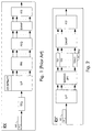
- the multicarrier receiver RX' drawn in Fig. 2 includes a serial to parallel converter S/P', a sliding fast Fourier transformer SLIDING FFT, a per-carrier frequency domain equaliser PC-FEQ ' , a demapper DMAP ' and a parallel to serial converter P/S'.
- the per-carrier frequency domain equaliser PC-FEQ contains Nu tapped delay lines where Nu is the number of used carriers in a multicarrier symbol, which has to be less than or equal to N/2, N being the FFT size.
- the tapped delay lines are indicated by TD1, TD2, ..., TDN/2 in Fig. 2.
- serial to parallel converter S/P ' the sliding fast Fourier transformer SLIDING FFT, the per-carrier frequency domain equaliser PC-FEQ, the demapper DMAP ' and the parallel to serial converter P/S ' are cascade coupled between an input port and output port of the multicarrier receiver RX'.
- the tapped delay lines TD1, TD2, ..., TDN/2 are coupled between respective outputs of the sliding fast Fourier transformer SLIDING FFT and respective inputs of the parallel to serial converter P/S'.
- the samples of the cyclically extended multicarrier symbol MS when received by the multicarrier receiver RX', are paralleled by the serial to parallel converter S/P' without having passed any equaliser.
- the extended multicarrier symbol MS then is supplied to the sliding fast Fourier transformer SLIDING FFT which converts different parts of the extended multicarrier symbol MS from time domain to frequency domain by calculating several consecutive Fourier transformations.
- the parts of the extended multicarrier symbol MS that are transformed all have the length of a non extended multicarrier symbol, i.e. the FFT size.
- the sliding fast Fourier transformer SLIDING FFT for example Fourier transforms a first part of the multicarrier symbol MS starting from the first sample of this multicarrier symbol MS.
- the length of the first part equals the length of a non-extended multicarrier symbol.
- the sliding fast Fourier transformer SLIDING FFT for example Fourier transforms a second part of the multicarrier symbol MS starting from the second sample of this multicarrier symbol MS. The length of this second part also equals the length of a non-extended multicarrier symbol. And so on.
- the sliding fast Fourier transformer SLIDING FFT in this way calculates at most an amount of Fourier transforms equal to the number taps of the tapped delay lines TD1, TD2, ..., TDN/2 in the per-carrier frequency domain equaliser PC-FEQ.
- the resulting frequency domain multicarrier symbols are applied to the per-carrier frequency domain equaliser PC-FEQ.
- each carrier is equalised by an individual equaliser or tapped delay line TD1, TD2, ..., TDN/2.
- Each tapped delay line TD1, TD2, ..., TDN/2 contains T complex taps.
- T Fourier transforms are thus calculated by the sliding fast Fourier transformer SLIDING FFT.
- the taps of a tapped delay line TD1 are adapted on the basis of a mean square error (MSE) criterion that optimises the signal to noise ratio (SNR) for transmission of that carrier over the transmission channel between multicarrier transmitter and multicarrier receiver RX ' .
- MSE mean square error
- the equalised carriers at the output of the per-carrier frequency domain equaliser PC-FEQ are applied to the demapper DMAP ' which decodes the exact amount of bits from each carrier using the appropriate constellation schemes and the bits sourced by this demapper DMAP ' are serialised by the parallel to serial converter P/S ' .
- the capacity of the multicarrier system is better optimised if the number of taps in the tapped delay lines TD1, TD2, ..., TDN/2 is not fixed but made controllable. In this way, the number of taps to equalise strongly affected carriers can be increased and the number of taps used to equalise less affected carriers or unused carriers is reduced.
- a controllable length of the tapped delay lines TD1, TD2, ..., TDN/2 however requires the presence of means which determine the length of the tapped delay lines TD1, TD2, ..., TDN/2 on the basis of for instance noise measurements at the different frequencies or on the basis of control signals indicating which carriers are used to transfer data by the multicarrier transmitter. Furthermore, it is noticed that in an embodiment with adaptive amounts of taps in the tapped delay lines TD1, TD2, ..., TDN/2, the sliding fast Fourier transformer SLIDING FFT has to calculate an amount of Fourier transforms equal to the largest number of taps in a tapped delay line.
- the time domain equaliser TEQ with its T taps requires T multiplications and T-1 additions to be performed in seconds.
- the frequency domain equaliser FEQ performs Nu complex multiplications per seconds since it is assumed that Nu carriers are used.
- the multicarrier receiver RX ' according to the present invention requires T fast Fourier transforms to be calculated and has at most N / 2 tapped delay lines TD1, TD2, ...,TDN/2 with T taps each. This seems to lead to a much higher total complexity. However, the vectors that are Fourier transformed, are formed by shifting the previous vector over one element and appending one new element.
- m is an index going from 1 to T-1
- Y(:,m+1) represents the (m+1)t-h column of matrix Y in expression (2) whose first element is given by y new
- Y(:,m) represents the m-th column of matrix Y whose last element is given by y old
- the sliding fast Fourier transformer SLIDING FFT consequently starts by calculating the Fourier transformation of the first column of matrix Y and deduces the T-1 other Fourier transforms therefrom via a linear combination of the Fourier transform samples and T-1 difference terms.
- the linear combinations can be incorporated in the per-carrier frequency domain equaliser PC-FEQ.
- the computational complexity of the per-carrier frequency domain equaliser PC-FEQ is proportional to the number of carriers used, Nu, and to the average length of the tapped delay lines TD1, TD2, ..., TDN/2 in case the number of taps is different for different tapped delay lines. Since the average length of the tapped delay lines TD1, TD2, ..., TDN/2 is significantly smaller than the length of the time domain equaliser TEQ in the known multicarrier receiver RX, the number of operations performed by the multicarrier receiver RX ' may be smaller than the amount of operations executed within the known multicarrier receiver RX or in the worst case, is of the some magnitude.
- the present invention is suitable for application in a multicarrier environment as ADSL (Asynchronous Digital Subscriber Line) or VDSL (Very High Speed Digital Subscriber Line) wherein the DMT (Discrete Multi Tone) multicarrier modulation is used.
- ADSL Asynchronous Digital Subscriber Line
- VDSL Very High Speed Digital Subscriber Line
- DMT Discrete Multi Tone multicarrier modulation
- applicability of the present invention is not restricted to a particular kind of transmission medium (twisted pair telephone line, coax cable, satellite link, ...) or to any particular kind of physical layer transfer protocol (ADSL, VDSL, ).
- the invention can be applied in any kind of multicarrier system making use of an FFT.
Priority Applications (9)
| Application Number | Priority Date | Filing Date | Title |
|---|---|---|---|
| EP98401609A EP0969637A1 (de) | 1998-06-29 | 1998-06-29 | Entzerrung in Mehrträgerempfänger |
| AT99401572T ATE284109T1 (de) | 1998-06-29 | 1999-06-24 | Mehrträgerempfänger mit rls- frequenzbereichsentzerrer pro träger |
| EP99401572A EP0967763B1 (de) | 1998-06-29 | 1999-06-24 | Mehrträgerempfänger mit RLS-Frequenzbereichsentzerrer pro Träger |
| DE69922297T DE69922297T2 (de) | 1998-06-29 | 1999-06-24 | Mehrträgerempfänger mit RLS-Frequenzbereichsentzerrer pro Träger |
| US09/340,207 US6744821B1 (en) | 1998-06-29 | 1999-06-28 | Multicarrier receiver |
| JP18210299A JP4229530B2 (ja) | 1998-06-29 | 1999-06-28 | マルチキャリア受信機 |
| AU36815/99A AU750466B2 (en) | 1998-06-29 | 1999-06-28 | A multicarrier receiver |
| IL13067199A IL130671A0 (en) | 1998-06-29 | 1999-06-28 | Multicarrier receiver |
| CA002276537A CA2276537A1 (en) | 1998-06-29 | 1999-06-28 | Multicarrier receiver |
Applications Claiming Priority (1)
| Application Number | Priority Date | Filing Date | Title |
|---|---|---|---|
| EP98401609A EP0969637A1 (de) | 1998-06-29 | 1998-06-29 | Entzerrung in Mehrträgerempfänger |
Publications (1)
| Publication Number | Publication Date |
|---|---|
| EP0969637A1 true EP0969637A1 (de) | 2000-01-05 |
Family
ID=8235417
Family Applications (1)
| Application Number | Title | Priority Date | Filing Date |
|---|---|---|---|
| EP98401609A Withdrawn EP0969637A1 (de) | 1998-06-29 | 1998-06-29 | Entzerrung in Mehrträgerempfänger |
Country Status (3)
| Country | Link |
|---|---|
| EP (1) | EP0969637A1 (de) |
| AT (1) | ATE284109T1 (de) |
| DE (1) | DE69922297T2 (de) |
Cited By (4)
| Publication number | Priority date | Publication date | Assignee | Title |
|---|---|---|---|---|
| EP1296492A1 (de) * | 2001-09-21 | 2003-03-26 | Alcatel | Mehrträgerempfänger mit einer Gleitfensterfouriertransformation und einer Fouriertransformation |
| WO2003039088A1 (de) * | 2001-10-31 | 2003-05-08 | Fliege J Norbert | Frequenzentzerrung für mehrtonübertragungssystem |
| EP1545083A1 (de) * | 2003-12-19 | 2005-06-22 | STMicroelectronics Belgium N.V. | Vorrichtung und Verfahren mit verringerter Complexität zum Entzerrung pro Träger in einem Mehrträgersystem |
| US7406141B1 (en) | 2000-08-21 | 2008-07-29 | Broadcom Corporation | Multi-band DMT receiver |
-
1998
- 1998-06-29 EP EP98401609A patent/EP0969637A1/de not_active Withdrawn
-
1999
- 1999-06-24 AT AT99401572T patent/ATE284109T1/de not_active IP Right Cessation
- 1999-06-24 DE DE69922297T patent/DE69922297T2/de not_active Expired - Lifetime
Non-Patent Citations (2)
| Title |
|---|
| CHOW P S ET AL: "A MULTICARRIER E1-HDSL TRANSCEIVER SYSTEM WITH CODED MODULATION", EUROPEAN TRANSACTIONS ON TELECOMMUNICATIONS AND RELATED TECHNOLOGIES, vol. 4, no. 3, 1 May 1993 (1993-05-01), pages 257 - 266, XP000385752 * |
| FARHANG-BOROUJENY B ET AL: "GENERALIZED SLIDING FFT AND ITS APPLICATION TO IMPLEMENTATION OF BLOCK LMS ADAPTIVE FILTERS", IEEE TRANSACTIONS ON SIGNAL PROCESSING, vol. 42, no. 3, 1 March 1994 (1994-03-01), pages 532 - 537, XP000450708 * |
Cited By (7)
| Publication number | Priority date | Publication date | Assignee | Title |
|---|---|---|---|---|
| US7406141B1 (en) | 2000-08-21 | 2008-07-29 | Broadcom Corporation | Multi-band DMT receiver |
| US7583742B2 (en) | 2000-08-21 | 2009-09-01 | Broadcom Corporation | Multi-band DMT receiver |
| EP1296492A1 (de) * | 2001-09-21 | 2003-03-26 | Alcatel | Mehrträgerempfänger mit einer Gleitfensterfouriertransformation und einer Fouriertransformation |
| US7126997B2 (en) | 2001-09-21 | 2006-10-24 | Alcatel | Multicarrier receiver |
| WO2003039088A1 (de) * | 2001-10-31 | 2003-05-08 | Fliege J Norbert | Frequenzentzerrung für mehrtonübertragungssystem |
| EP1545083A1 (de) * | 2003-12-19 | 2005-06-22 | STMicroelectronics Belgium N.V. | Vorrichtung und Verfahren mit verringerter Complexität zum Entzerrung pro Träger in einem Mehrträgersystem |
| US8102924B2 (en) | 2003-12-19 | 2012-01-24 | Stmicroelectronics N.V. | Arrangements and methods for per tone equalization with reduced complexity |
Also Published As
| Publication number | Publication date |
|---|---|
| DE69922297T2 (de) | 2005-11-24 |
| DE69922297D1 (de) | 2005-01-05 |
| ATE284109T1 (de) | 2004-12-15 |
Similar Documents
| Publication | Publication Date | Title |
|---|---|---|
| AU750466B2 (en) | A multicarrier receiver | |
| US7561627B2 (en) | Method and system for channel equalization and crosstalk estimation in a multicarrier data transmission system | |
| US6097763A (en) | MMSE equalizers for DMT systems with cross talk | |
| CA2347252C (en) | Transmitter and method for transmitting a pattern in a multicarrier modulation transmission system | |
| US6400781B1 (en) | Multiband detector | |
| US7623578B2 (en) | Time domain equalization using frequency domain operations | |
| US7020212B1 (en) | Method and system for a multiple dimensional adaptive frequency domain noise canceler for DMT transceivers | |
| US7643582B2 (en) | Method and system for determining symbol boundary timing in a multicarrier data transmission system | |
| JP2000307481A (ja) | ウィンドウ関数を有する離散複数トーン被変調信号のための受信装置 | |
| US7224725B2 (en) | Method for determining coefficients of an equalizer and apparatus for determining the same | |
| WO2005125133A1 (en) | Method and system for channel estimation in a data transmission system | |
| US6563841B1 (en) | Per-bin adaptive equalization in windowed DMT-type modem receiver | |
| US7031379B2 (en) | Time domain equalizer for DMT modulation | |
| EP1420557B1 (de) | Kombinierte Entzerrung für einen DMT-Empfänger | |
| US6252902B1 (en) | xDSL modem having DMT symbol boundary detection | |
| EP0700189B1 (de) | Verfahren und Vorrichtung für die Entzerrung von digitalen Signalen im Frequenzbereich | |
| EP0969637A1 (de) | Entzerrung in Mehrträgerempfänger | |
| US6687288B1 (en) | NEXT cancellation for modem pools | |
| EP1545083B1 (de) | Vorrichtung und Verfahren mit verringerter Complexität zum Entzerrung pro Träger in einem Mehrträgersystem | |
| EP1296492B1 (de) | Mehrträgerempfänger mit einer Gleitfensterfouriertransformation und einer Fouriertransformation | |
| KR100440833B1 (ko) | 이산 멀티톤 변조를 이용하여 발생시킨 신호를 위한디지탈 수신기 | |
| EP1303093B1 (de) | Verkürzung der Impulsantwort in DMT-Modems | |
| EP1434401A1 (de) | Zeitbereichsentzerrung mittels Operationen im Frequenzbereich | |
| Helms | A simple RLS-POCS solution for reduced complexity ADSL impulse shortening |
Legal Events
| Date | Code | Title | Description |
|---|---|---|---|
| PUAI | Public reference made under article 153(3) epc to a published international application that has entered the european phase |
Free format text: ORIGINAL CODE: 0009012 |
|
| AK | Designated contracting states |
Kind code of ref document: A1 Designated state(s): AT BE DE ES FR GB IT SE |
|
| AX | Request for extension of the european patent |
Free format text: AL;LT;LV;MK;RO;SI |
|
| 17P | Request for examination filed |
Effective date: 20000705 |
|
| AKX | Designation fees paid |
Free format text: AT BE DE ES FR GB IT SE |
|
| STAA | Information on the status of an ep patent application or granted ep patent |
Free format text: STATUS: THE APPLICATION HAS BEEN WITHDRAWN |
|
| 18W | Application withdrawn |
Withdrawal date: 20011020 |