EP0969415A2 - Techniques d'affichage pour réalité virtuelle tridimensionnelle - Google Patents
Techniques d'affichage pour réalité virtuelle tridimensionnelle Download PDFInfo
- Publication number
- EP0969415A2 EP0969415A2 EP99304906A EP99304906A EP0969415A2 EP 0969415 A2 EP0969415 A2 EP 0969415A2 EP 99304906 A EP99304906 A EP 99304906A EP 99304906 A EP99304906 A EP 99304906A EP 0969415 A2 EP0969415 A2 EP 0969415A2
- Authority
- EP
- European Patent Office
- Prior art keywords
- image
- dimensional
- world
- user
- dimensional image
- Prior art date
- Legal status (The legal status is an assumption and is not a legal conclusion. Google has not performed a legal analysis and makes no representation as to the accuracy of the status listed.)
- Withdrawn
Links
Images


Classifications
-
- G—PHYSICS
- G06—COMPUTING; CALCULATING OR COUNTING
- G06T—IMAGE DATA PROCESSING OR GENERATION, IN GENERAL
- G06T15/00—3D [Three Dimensional] image rendering
- G06T15/10—Geometric effects
Definitions
- This invention relates to the integration of three-dimensional computer graphics and a two-dimensional image to provide a realistic three-dimensional virtual reality experience.
- a limitation of such a world occurs when a user moves within the world and views the world from a location different than the original context of a two-dimensional image carefully calibrated to "fit into” the world.
- View changes such as from a location different than the image's ideal viewing point, result in the image not aligning or fitting well with the surrounding objects of the three-dimensional world.
- viewpoint changes may be dealt with by distorting the two-dimensional image so as to adjust the image's vanishing point(s) in accordance with the movement of the user. In this manner, as the user moves away from the ideal viewing point, the distortions act to limit the discontinuities between the two-dimensional image and the surroundings of the world.
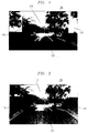
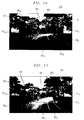
- FIGs. 1-2 show examples of that which a user sees when the user moves within a three-dimensional virtual reality world and views a two-dimensional image representing a portion of the world from a location at the image's ideal viewing point (IVP), and then from a different location, i.e., a location different than the original context of the image.
- IVP ideal viewing point
- the two-dimensional image has been carefully calibrated to "fit into” the surroundings of the world.
- discontinuities between the two-dimensional image and its surroundings are minimized by distorting the image according to the movement of the user.
- Fig. 1 shows an exemplary three-dimensional reality world 105, which is a bicycle path in a park, e.g., Central Park in New York City.
- the present invention exploits a characteristic common to images consisting of views looking down the center of roads, streets or paths, which is that they may be treated as perspective, corridor-like images, with features closer to the center of the image being farther away from the viewer.
- the bicycle path or road and its immediate vicinity are treated as a kind of three-dimensional, corridor-like image whose floor is formed by the roadbed, whose ceiling is formed by the sky, and whose sidewalls are formed by the roadside objects.
- the principles of a simple point perspective can be used for distorting the landscape image in accordance with the movement of the viewer. as discussed hereinbelow.
- World 105 is divided into two portions, screen or panel 110 on which is shown or displayed a two-dimensional image 115, such as a still photograph, picture, or a current frame of a video clip; and the remainder of the world 120, which is represented using computer graphics techniques, and is thus referred to herein as computer graphics (GC Part) 120.
- CG Part 120 there are various synthetic, three-dimensional landscapes or objects modeled in, for example, the Virtual Reality Modeling Language (VRML).
- Two-dimensional image 115 simulates landscape or terrain portions of the world 105, here a virtual road or course 125 for walking, running or pedaling a bicycle.
- VRML Virtual Reality Modeling Language
- three-dimensional world 105 cannot be actually rendered in a two-dimensional plane, it can be projected to and displayed on a two-dimensional plane so as to appear to have three dimensions. Accordingly, the techniques of the present invention are preferably employed with computers and software, which are sufficiently sophisticated to display images on a two-dimensional plane as having three dimensions. Note also that to make the world look realistic, computer graphics display techniques use the z component of objects to scale accordingly the x and y components as a function of its distance to the user's viewpoint.
- Two-dimensional image 115 is carefully placed, cropped and sized to achieve continuity with the surrounding environment of the CG Part 120. Note that the image is clipped so that the left and right edges of the road in CG Part 120 pass through the left and right bottom corners of the road, respectively, in image 115. This clipping ensures that the roadbed maps to the floor of the hypothetical corridor. In so doing, portions at the boundary between two-dimensional image 115 and CG part 120 are co-planar, i.e., at the same distance away from the user's viewpoint. In "fitting" two-dimensional image 115 to CG part 120, however, there exits only one viewpoint from which that image's content properly corresponds to the surrounding environment of CG Part 120. This unique location is called the image's ideal viewing point (IVP). In Fig. 1, two-dimensional image 115 is seen from its ideal viewing point, and from this view, image 115 aligns well with the surrounding objects of CG Part 120.
- IVP image's ideal viewing point
- image 115 Users, however, rarely view image 115 only from its idea viewing point. As the user moves within world 105, such as left or right of road 125, as they round curves, or move closer to or farther from the image, they see image 115 from positions other than its ideal viewing point. Absent the use of the present invention, such viewpoint changes would cause objects or features within image 115 to align improperly with the surrounding environment, as further illustrated in Fig. 2.
- screen or panel 110 uses a display structure called a "pyramidic panel structure" for displaying two-dimensional image 115 within the surrounding three-dimensional space of the CG Part 105 so as to deal with viewpoint changes.
- the transformations associated with the pyramidic panel structure dynamically distort two-dimensional image 115 according to viewer's position so as to adjust the image's vanishing point with the viewer's movement. As the viewer moves from the image's ideal viewing point, these distortions act to limit discontinuities between image 115 and the surroundings of CG Part 120.
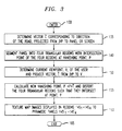
- Fig. 3 shows an exemplary process in accordance with the principles of the invention for distorting two-dimensional image 115 so as to adjust its vanishing point in accordance with the viewer's position.
- the process is entered at step 130 whenever it is determined that the viewer's position has changed.
- a vector, C corresponding to the direction of road 125 is projected at step 135 from the image's ideal viewing point, IVP, to panel or screen 110 on which is displayed image 115.
- the panel is two-dimensional, but represents three-dimensional space with objects nearer the center of the image being farther away from the plane of the viewer.
- the panel structure is shown in Fig. 4.
- the point of intersection with screen or panel 110 is the image's vanishing point, P. Note, however, that the vanishing point may be set visually by the user, if desired, or by other suitable computer graphics processing techniques known in the art.
- screen or panel 110 is segmented into four triangular regions 145 1-4 , one for each of the regions bordering CG Part 120, with the intersection point of the four regions located at the vanishing point, P.
- step 150 the current viewpoint of the user, V, is determined, and a vector T projected from the ideal viewing point, IVP, to the viewer's current location, V.
- the four triangular regions 145 1-4 are distorted in the three-dimensional space of the virtual world at step 155 to represent the mapping of objects nearer the center of the image being displaced farther away from the viewpoint of the user.
- the four triangular regions intersect at the new vanishing point P ' and form so-called "pyramidic panels" 145' 1-4 . This is illustrated in Fig. 5.
- the corresponding images displayed in regions 145 1-4 are then "texture-mapped" onto pyramidic panels 145' 1-4 , respectively.
- IVP distortions in the image resulting from moving the image's vanishing point from P to P ' act to limit the discontinuities between image 115 and the surroundings within CG Part 105.
- distorting image 115 so as to move the vanishing point from P to P ' results in pyramidic panel structure forming a four-sided pyramid. Note that its base is fixed and corresponds to original screen or panel 110, with its peak located at P ', which moves in concert with the viewer's current location, V. As the user's viewpoint moves closer to and farther from the image, the image's vanishing point accordingly moves farther from and closer to the user's viewpoint, respectively.
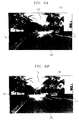
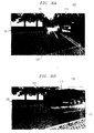
- Figs. 6 through 8 compare the display of two-dimensional image 115 on screen or panel 110 with the display of the same image using the "pyramidic" panels of the present invention. More specifically, Figs. 6A, 7A and 8A depict viewing two-dimensional image 115 at a location from the left, above, and in front and to the right of the image's ideal viewing point, IVP, respectively, without the use of the present invention. In these latter figures, note that there are discontinuities between the edges of the road and the three-dimensional space of CG Part 105. Figs. 6B, 7B and 8C depict the same two-dimensional image distorted and texture-mapped onto pyramidic panels 145' 1-4 , in accordance with the principles of the invention. Note that in these latter figures, the discontinuities in the road edge have been substantially eliminated.
- a modified pyramidic panel structure may be used to deal with two-dimensional images containing curved roads, streets, paths and other corridor-like images containing multiple rather than a single vanishing point.
- screen or panel 110 is segmented using multiple vanishing points to form a so called “articulated pyramidic panel structure.”
- the transformations associated with the articulated pyramidic panel structure dynamically distort different portions of two-dimensional image 115 according to viewer positions so as to adjust the different vanishing points of the image with the viewer's movement. Likewise, as the viewer moves from the image's ideal viewing point, these distortions act to limit the discontinuities between two-dimensional image 115 and the surroundings of CG Part 120.
- Fig. 9 shows an exemplary process in accordance with the principles of the invention for distorting two-dimensional image 115 using an articulated pyramidic panel structure. Again, the process is entered at step 170 whenever it is determined that the viewer's position has changed.
- curve road 125 is treated as two straight corridors placed end-to-end, extending back from screen or panel 110. Each corridor represents a different portion of road 125 in the three-dimensional space of world 105, with features nearer the center of the image being farther away from the user's viewpoint.
- corresponding directional vectors C 1 and C 2 of the corridors are determined at step 175. Note that portion of the road nearer to the user's viewpoint is represented by C 1 , and the portion farther away is represented by C 2 .
- the corresponding vanishing points P 1 and P 2 are determined, respectively, for each corridor by projecting those vectors from the image's ideal viewing point, IVP. Alternatively, vanishing points P 1 and P 2 may be determined visually by the user, or by some other suitable means known in the art.
- step 185 using the first corridor's vanishing point, P 1 , a first set of pyramidic panels 190 1-4 are constructed to intersect at vanishing point, P 1 , as shown in Fig. 10.
- the current viewpoint of the user, V is determined, and a vector T projected from the ideal viewing point, IVP, to the viewer's current location, V (step 210).
- the corresponding images in original panels are then texture-mapped into articulated pyramidic panels 190 1-4 and 200 1-4 , which have been distorted in accordance with the movement of the viewer.
- these panels are each subdivided into two triangular subregions and then texture-mapped. Shown in Fig. 11 is image 115 seen from a location away from the image's ideal viewing point, using the articulated pyramidic panel structure of the present invention.
- each set of articulated pyramidic panels may also use more than two sets of pyramidic panel structures.
- multiple corridors may be employed, each placed end-to-end and extending back from screen or panel 110.
- each corridor represents a different portion of road 125 in the three-dimensional space of world 105, with features nearer the center of the image being farther away from the user's viewpoint.
- each set of articulated pyramidic panels are formed reitererately using the above described procedure.
Landscapes
- Physics & Mathematics (AREA)
- Engineering & Computer Science (AREA)
- Geometry (AREA)
- Computer Graphics (AREA)
- General Physics & Mathematics (AREA)
- Theoretical Computer Science (AREA)
- Processing Or Creating Images (AREA)
- Stereoscopic And Panoramic Photography (AREA)
- Studio Circuits (AREA)
- Management, Administration, Business Operations System, And Electronic Commerce (AREA)
Applications Claiming Priority (2)
| Application Number | Priority Date | Filing Date | Title |
|---|---|---|---|
| US107059 | 1998-06-30 | ||
| US09/107,059 US6229548B1 (en) | 1998-06-30 | 1998-06-30 | Distorting a two-dimensional image to represent a realistic three-dimensional virtual reality |
Publications (1)
| Publication Number | Publication Date |
|---|---|
| EP0969415A2 true EP0969415A2 (fr) | 2000-01-05 |
Family
ID=22314630
Family Applications (1)
| Application Number | Title | Priority Date | Filing Date |
|---|---|---|---|
| EP99304906A Withdrawn EP0969415A2 (fr) | 1998-06-30 | 1999-06-23 | Techniques d'affichage pour réalité virtuelle tridimensionnelle |
Country Status (3)
| Country | Link |
|---|---|
| US (1) | US6229548B1 (fr) |
| EP (1) | EP0969415A2 (fr) |
| JP (1) | JP2000076481A (fr) |
Cited By (1)
| Publication number | Priority date | Publication date | Assignee | Title |
|---|---|---|---|---|
| CN104182632A (zh) * | 2014-08-21 | 2014-12-03 | 北京航空航天大学 | 一种基于扰动图像的长时间曝光深空视景仿真图像合成方法 |
Families Citing this family (13)
| Publication number | Priority date | Publication date | Assignee | Title |
|---|---|---|---|---|
| JP3597792B2 (ja) | 2001-04-05 | 2004-12-08 | コナミ株式会社 | 3次元画像処理方法、装置、3次元画像処理プログラム及びビデオゲーム装置 |
| JP3966830B2 (ja) | 2003-03-28 | 2007-08-29 | 株式会社東芝 | 立体表示装置 |
| US7239331B2 (en) * | 2004-02-17 | 2007-07-03 | Corel Corporation | Method and apparatus for correction of perspective distortion |
| US20080018668A1 (en) * | 2004-07-23 | 2008-01-24 | Masaki Yamauchi | Image Processing Device and Image Processing Method |
| JP2006318015A (ja) * | 2005-05-10 | 2006-11-24 | Sony Corp | 画像処理装置および画像処理方法、画像表示システム、並びに、プログラム |
| JP4759524B2 (ja) * | 2007-01-09 | 2011-08-31 | 富士フイルム株式会社 | 電子式手振れ補正方法及びその装置並びに電子式手振れ補正プログラムと撮像装置 |
| US20120197428A1 (en) * | 2011-01-28 | 2012-08-02 | Scott Weaver | Method For Making a Piñata |
| KR102115930B1 (ko) * | 2013-09-16 | 2020-05-27 | 삼성전자주식회사 | 디스플레이 장치 및 영상 처리 방법 |
| KR102145574B1 (ko) * | 2013-11-29 | 2020-08-18 | (주)문화유산기술연구소 | 실제 길거리에 어우러진 가상 영상 출력 시스템 |
| CN105094335B (zh) * | 2015-08-04 | 2019-05-10 | 天津锋时互动科技有限公司 | 场景提取方法、物体定位方法及其系统 |
| CN105354873B (zh) * | 2015-09-18 | 2018-07-06 | 四川大学 | 用于多孔介质三维重构的模式密度函数模拟方法 |
| CN112969035A (zh) * | 2021-01-29 | 2021-06-15 | 新华智云科技有限公司 | 一种可视化视频制作方法及制作系统 |
| CN113012490A (zh) * | 2021-03-09 | 2021-06-22 | 沙艾霖 | 一种基于虚拟场景的语言学习系统及装置 |
Family Cites Families (3)
| Publication number | Priority date | Publication date | Assignee | Title |
|---|---|---|---|---|
| US5124693A (en) * | 1985-10-29 | 1992-06-23 | International Business Machines | Three dimensional graphic display with user defined vanishing point |
| US5261041A (en) * | 1990-12-28 | 1993-11-09 | Apple Computer, Inc. | Computer controlled animation system based on definitional animated objects and methods of manipulating same |
| US5748199A (en) * | 1995-12-20 | 1998-05-05 | Synthonics Incorporated | Method and apparatus for converting a two dimensional motion picture into a three dimensional motion picture |
-
1998
- 1998-06-30 US US09/107,059 patent/US6229548B1/en not_active Expired - Lifetime
-
1999
- 1999-06-23 EP EP99304906A patent/EP0969415A2/fr not_active Withdrawn
- 1999-06-28 JP JP18235299A patent/JP2000076481A/ja active Pending
Cited By (2)
| Publication number | Priority date | Publication date | Assignee | Title |
|---|---|---|---|---|
| CN104182632A (zh) * | 2014-08-21 | 2014-12-03 | 北京航空航天大学 | 一种基于扰动图像的长时间曝光深空视景仿真图像合成方法 |
| CN104182632B (zh) * | 2014-08-21 | 2017-04-26 | 北京航空航天大学 | 一种基于扰动图像的长时间曝光深空视景仿真图像合成方法 |
Also Published As
| Publication number | Publication date |
|---|---|
| US6229548B1 (en) | 2001-05-08 |
| JP2000076481A (ja) | 2000-03-14 |
Similar Documents
| Publication | Publication Date | Title |
|---|---|---|
| US6504535B1 (en) | Display techniques for three-dimensional virtual reality | |
| US4985854A (en) | Method for rapid generation of photo-realistic imagery | |
| El-Hakim et al. | A multi-sensor approach to creating accurate virtual environments | |
| Neumann et al. | Augmented virtual environments (ave): Dynamic fusion of imagery and 3d models | |
| EP0451875B1 (fr) | Système d'affichage d'image | |
| US6229548B1 (en) | Distorting a two-dimensional image to represent a realistic three-dimensional virtual reality | |
| US20110211040A1 (en) | System and method for creating interactive panoramic walk-through applications | |
| JP2003518673A (ja) | 3d環境ラベリング | |
| JPH0757117A (ja) | テクスチャマップへの索引を生成する方法及びコンピュータ制御表示システム | |
| GB2244412A (en) | Simulating non-homogeneous fog with a plurality of translucent layers | |
| Brosz et al. | Single camera flexible projection | |
| CN101122464A (zh) | 一种gps导航系统中道路显示方法、装置及设备 | |
| US6236402B1 (en) | Display techniques for three-dimensional virtual reality | |
| Möser et al. | Context aware terrain visualization for wayfinding and navigation | |
| US20030146922A1 (en) | System and method for diminished reality | |
| US20030052891A1 (en) | System, method and computer program product for global rendering | |
| US6351262B1 (en) | Display techniques for three-dimensional virtual reality | |
| EP1745440B1 (fr) | Pipeline graphique pour rendre des graphiques | |
| CN111524230A (zh) | 一种三维模型与展开全景图联动浏览方法及计算机系统 | |
| US6567085B1 (en) | Display techniques for three-dimensional virtual reality | |
| Brédif | Image-based rendering of lod1 3d city models for traffic-augmented immersive street-view navigation | |
| WO1999052078A1 (fr) | Procede et systeme pour realiser un rendu polygonal au moyen d'un moteur de configuration specialise | |
| JP4530214B2 (ja) | 模擬視界発生装置 | |
| KR100848687B1 (ko) | 3차원 그래픽 처리 장치 및 그것의 동작 방법 | |
| Ono et al. | A photo-realistic driving simulation system for mixed-reality traffic experiment space |
Legal Events
| Date | Code | Title | Description |
|---|---|---|---|
| PUAI | Public reference made under article 153(3) epc to a published international application that has entered the european phase |
Free format text: ORIGINAL CODE: 0009012 |
|
| AK | Designated contracting states |
Kind code of ref document: A2 Designated state(s): AT BE CH CY DE DK ES FI FR GB GR IE IT LI LU MC NL PT SE |
|
| AX | Request for extension of the european patent |
Free format text: AL;LT;LV;MK;RO;SI |
|
| STAA | Information on the status of an ep patent application or granted ep patent |
Free format text: STATUS: THE APPLICATION HAS BEEN WITHDRAWN |
|
| 18W | Application withdrawn |
Withdrawal date: 20021120 |