EP0968902A2 - Power steering reservoir and cooler - Google Patents
Power steering reservoir and cooler Download PDFInfo
- Publication number
- EP0968902A2 EP0968902A2 EP99304846A EP99304846A EP0968902A2 EP 0968902 A2 EP0968902 A2 EP 0968902A2 EP 99304846 A EP99304846 A EP 99304846A EP 99304846 A EP99304846 A EP 99304846A EP 0968902 A2 EP0968902 A2 EP 0968902A2
- Authority
- EP
- European Patent Office
- Prior art keywords
- cooling liquid
- hydraulic fluid
- transfer passage
- baffle
- canister
- Prior art date
- Legal status (The legal status is an assumption and is not a legal conclusion. Google has not performed a legal analysis and makes no representation as to the accuracy of the status listed.)
- Granted
Links
- 239000000110 cooling liquid Substances 0.000 claims abstract description 97
- 239000012530 fluid Substances 0.000 claims abstract description 75
- 238000001816 cooling Methods 0.000 claims abstract description 19
- 239000002826 coolant Substances 0.000 description 1
- 230000008030 elimination Effects 0.000 description 1
- 238000003379 elimination reaction Methods 0.000 description 1
- 238000001914 filtration Methods 0.000 description 1
- 239000010720 hydraulic oil Substances 0.000 description 1
- 238000009434 installation Methods 0.000 description 1
- 239000007788 liquid Substances 0.000 description 1
- 238000012986 modification Methods 0.000 description 1
- 230000004048 modification Effects 0.000 description 1
Images

Classifications
-
- B—PERFORMING OPERATIONS; TRANSPORTING
- B62—LAND VEHICLES FOR TRAVELLING OTHERWISE THAN ON RAILS
- B62D—MOTOR VEHICLES; TRAILERS
- B62D5/00—Power-assisted or power-driven steering
- B62D5/06—Power-assisted or power-driven steering fluid, i.e. using a pressurised fluid for most or all the force required for steering a vehicle
- B62D5/062—Details, component parts
-
- F—MECHANICAL ENGINEERING; LIGHTING; HEATING; WEAPONS; BLASTING
- F15—FLUID-PRESSURE ACTUATORS; HYDRAULICS OR PNEUMATICS IN GENERAL
- F15B—SYSTEMS ACTING BY MEANS OF FLUIDS IN GENERAL; FLUID-PRESSURE ACTUATORS, e.g. SERVOMOTORS; DETAILS OF FLUID-PRESSURE SYSTEMS, NOT OTHERWISE PROVIDED FOR
- F15B1/00—Installations or systems with accumulators; Supply reservoir or sump assemblies
- F15B1/26—Supply reservoir or sump assemblies
-
- F—MECHANICAL ENGINEERING; LIGHTING; HEATING; WEAPONS; BLASTING
- F01—MACHINES OR ENGINES IN GENERAL; ENGINE PLANTS IN GENERAL; STEAM ENGINES
- F01P—COOLING OF MACHINES OR ENGINES IN GENERAL; COOLING OF INTERNAL-COMBUSTION ENGINES
- F01P2060/00—Cooling circuits using auxiliaries
-
- F—MECHANICAL ENGINEERING; LIGHTING; HEATING; WEAPONS; BLASTING
- F15—FLUID-PRESSURE ACTUATORS; HYDRAULICS OR PNEUMATICS IN GENERAL
- F15B—SYSTEMS ACTING BY MEANS OF FLUIDS IN GENERAL; FLUID-PRESSURE ACTUATORS, e.g. SERVOMOTORS; DETAILS OF FLUID-PRESSURE SYSTEMS, NOT OTHERWISE PROVIDED FOR
- F15B21/00—Common features of fluid actuator systems; Fluid-pressure actuator systems or details thereof, not covered by any other group of this subclass
- F15B21/04—Special measures taken in connection with the properties of the fluid
- F15B21/042—Controlling the temperature of the fluid
- F15B21/0423—Cooling
-
- Y—GENERAL TAGGING OF NEW TECHNOLOGICAL DEVELOPMENTS; GENERAL TAGGING OF CROSS-SECTIONAL TECHNOLOGIES SPANNING OVER SEVERAL SECTIONS OF THE IPC; TECHNICAL SUBJECTS COVERED BY FORMER USPC CROSS-REFERENCE ART COLLECTIONS [XRACs] AND DIGESTS
- Y10—TECHNICAL SUBJECTS COVERED BY FORMER USPC
- Y10S—TECHNICAL SUBJECTS COVERED BY FORMER USPC CROSS-REFERENCE ART COLLECTIONS [XRACs] AND DIGESTS
- Y10S165/00—Heat exchange
- Y10S165/916—Oil cooler
Definitions
- the invention relates to power steering reservoirs, particularly on heavy duty trucks and busses, and the need to dissipate heat within the system, in reduced space and with lower cost.
- One function of power steering reservoirs on heavy duty trucks and busses is to dissipate heat generated within the system.
- a larger reservoir is used when additional cooling is required.
- a hydraulic fluid cooler is also required to reduce the operating temperature to an acceptable level.
- the hydraulic fluid cooling device is typically connected to the return hose between the power steering gear and the reservoir, i.e. a series connection with two additional hose connections.
- Truck aerodynamic improvements are limiting the amount of air flow through the engine compartment. This reduction in air flow also reduces the cooling efficiency of the power steering reservoir. Sloping front hoods are reducing under hood space, which makes larger reservoirs impractical.
- the present invention addresses and solves the above-noted need in a particularly simple and cost effective manner.
- the invention enables elimination of a hydraulic cooler otherwise connected in series between the power steering gear and the reservoir, and eliminates the two extra hose connections therefor.
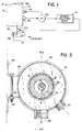
- Fig. 1 is a schematic illustration of a power steering system incorporating the present invention.
- Fig. 2 is a side view partially in section of a combined power steering hydraulic fluid reservoir and cooling unit constructed in accordance with the invention.
- Fig. 3 is a sectional view taken along line 3-3 of Fig. 2.
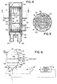
- Fig. 4 is a sectional view of a portion of the structure of Fig. 2.
- Fig. 5 is a sectional view taken along line 5-5 of Fig. 4.
- Fig. 6 is a view like Fig. 1 and shows a further embodiment.
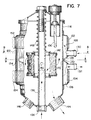
- Fig. 7 is a view like Fig. 2 and shows a further embodiment.
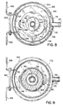
- Fig. 8 is a sectional view taken along line 8-8 of Fig. 7.
- Fig. 9 is a sectional view taken along line 9-9 of Fig. 7.
- Fig. 1 shows a combined power steering hydraulic fluid reservoir and cooling unit 12 including a housing 14 having a reservoir tank 16 for receiving and collecting hydraulic fluid from a power steering gear 18 and holding the hydraulic fluid in readiness for supply to a hydraulic pump 20.
- the housing has a heat exchanger 22 with a cooling liquid flow path therethrough in heat transfer relation with the hydraulic fluid, eliminating a hydraulic fluid cooler otherwise connected in series between power steering gear 18 and tank 16, and eliminating the two extra hose connections therefor.
- Housing 14 has a first hose connection 24 providing a hydraulic fluid inlet, a second hose connection 26 providing a hydraulic fluid outlet, a third hose connection 28 providing a cooling liquid inlet, and a fourth hose connection 30 providing a cooling liquid outlet.
- the housing may include a further hydraulic fluid inlet 32 as a bypass receiving excess flow from pump 20.
- Fig. 2 shows reservoir tank 14, which is Nelson Industries Part No. 94131A, modified in accordance with the present invention.
- the tank is a cylindrical canister extending axially along a vertical axis 34 between distally opposite lower and upper axial ends 36 and 38.
- Extending through lower axial end 36 is heat exchanger 22, provided by a Serck Part No. 31002-97-AA01.
- Heat exchanger 22 extends axially along axis 34 through axial end 36 of reservoir tank 16.
- the cooling liquid flow path through heat exchanger 22 is in heat transfer relation with hydraulic fluid in tank 16.
- Heat exchanger 22 has a side wall 40 extending axially between distally opposite lower and upper end walls 42 and 44. Cooling liquid inlet 28 and cooling liquid outlet 30 both extend axially through lower end wall 42. Hydraulic fluid inlet 24 extends radially through side wall 40. Side wall 40 of heat exchanger 22 extends axially through lower axial end 36 of reservoir tank 16. Side wall 40 of heat exchanger 22 has a first portion 46 exterior to reservoir tank 16, and a second portion 48 interior to reservoir tank 16. Hydraulic fluid inlet 24 extends radially through first portion 46 of side wall 40. Second portion 48 of side wall 40 has a pair of openings 50, 52, Figs. 2, 4 and 5, therethrough passing hydraulic fluid into lower portion 54 of tank 16 below divider wall 55.
- Coolant liquid flows from heat exchanger inlet 28 into lower entry plenum 56, Fig. 4, then upwardly through a plurality of transfer tubes 58 to upper plenum 60 then downwardly through a plurality of transfer tubes 62 to lower exit plenum 64 then to cooling liquid outlet 30. Entrance and exit plenums 56 and 64 are separated by dividing wall 66. Hydraulic fluid flows from hydraulic fluid inlet 24 into heat exchanger 22 and is directed around tubes 62, 58 in a tortuous flow path 68 by directional divider walls 70, 72, and then flows through openings 50, 52 into lower portion 54 of tank 16. The hydraulic fluid then flows upwardly as shown at arrow 74, Fig.
- a pair of mounting bands or straps 88, 90 extend around the housing and have ends such as 92, 94, Fig. 3, mountable to a vertical surface in the engine compartment, such as a fire wall, etc., and tightenable by a bolt 96.
- Fig. 6 is like Fig. 1 and shows a further embodiment of a combined power steering hydraulic fluid reservoir and cooling unit 112 including a housing 114 having a reservoir tank 116 for receiving and collecting hydraulic fluid from power steering gear 18 and holding the hydraulic fluid in readiness for supply to hydraulic pump 20.
- the tank is provided by a cylindrical canister extending axially along vertical axis 34.
- the housing has a heat exchanger 122 with a cooling liquid flow path therethrough in heat transfer relation with the hydraulic fluid in tank 116.
- the heat exchanger is provided by an annular jacket around the canister.
- the jacket has upper and lower axially spaced annular chambers 124 and 126 separated by a circumferential divider wall or baffle 128 therebetween.
- Annular chamber 124 has a cooling liquid inlet 130, and annular chamber 126 has a cooling liquid outlet 132.
- Baffle 128 has a transfer passage 134 therethrough, Figs. 6-9, such that the cooling liquid flow path is through cooling liquid inlet 130, then through annular chamber 124, then through transfer passage 134, then through annular chamber 126, then through cooling liquid outlet 132.
- the hydraulic fluid flow path is from hydraulic fluid inlet 136, Figs. 6, 7, then upwardly through central standpipe 138, then radially outwardly through apertures 140 then through filter 142 against the side wall of tank 116, then to hydraulic fluid outlet 144.
- Bypass inlet 146 to the tank is provided for receiving excess flow from pump 20.
- a pair of mounting bands or straps 152, 154 extend around jacket 122 and have ends such as 156, 158, Figs. 8 and 9, mountable to a vertical surface in the engine compartment such as a fire wall, etc., and tightenable by a bolt 160.
- Baffle 128 is C-shaped in radial cross section as shown at 162 in Fig. 8.
- the facing ends 164 and 166 of the C-shape 162 define transfer passage 134 in the circumferential arcuate gap 166 therebetween.
- Transfer passage 134 extends axially along canister 116 between annular chambers 124 and 126.
- Jacket 122 is an annular sleeve having a side wall 168 spaced radially outwardly of canister 116 to define an annular space therebetween.
- Baffle 128 is provided by a recessed groove formed in side wall 168 of the sleeve and extending radially inwardly towards side wall 170 of the canister.
- the groove extends partially circumferentially around the canister and divides the annular space into the noted annular chambers 124 and 126 and provides the noted C-shaped baffle therebetween.
- Cooling liquid inlet 130 and cooling liquid outlet 132 are diametrically opposite gap 166 between facing ends 162 and 164 of the C-shape 162.
- Baffle groove 128 is V-shaped in axial cross-section, Fig. 7, with the apex 172 of the V engaging tank 116 at side wall 170.
- transfer passage 134 through baffle 128 is diametrically opposite cooling liquid inlet 130 along the circumference of cylindrical canister 116 such that cooling liquid from cooling liquid inlet 130 splits into two paths in annular chamber 124, a path 174, Fig. 8, traversing 180° in a semi-circle to transfer passage 134, and a path 176 traversing oppositely from first path 174 and 180° in a semi-circle to transfer passage 134, such that cooling liquid from cooling liquid inlet 130 splits into two paths 174, 176 and then rejoins at transfer passage 134.
- Transfer passage 134 is diametrically opposite cooling liquid outlet 132 along the circumference of cylindrical canister 116 such that cooling liquid from transfer passage 134 splits into two paths in annular chamber 126, a path traversing 180° in a semi-circle to cooling liquid outlet 132, and another path traversing oppositely and 180° in a semi-circle to cooling liquid outlet 132, such that cooling liquid from transfer passage 134 splits into two paths and then rejoins at cooling liquid outlet 132.
- Hydraulic fluid flows radially outwardly through filter 142 and against side wall portion 170 of canister 116.
- Jacket 122 is around portion 170 of the side wall of the canister and provides the noted cooling chamber thereat. Hydraulic fluid exiting from filter 142 flows against cooled portion 170 of the side wall of the canister and gives up heat to cooling liquid in cooling chambers 124, 126 provided by jacket 122, such that hydraulic fluid is filtered first and cooled second. This is preferred because there is then less pressure drop at the cooling interface, and because filtering of hot fluid reduces the chance of bypass spring 148 opening.
Landscapes
- Engineering & Computer Science (AREA)
- Mechanical Engineering (AREA)
- Chemical & Material Sciences (AREA)
- Combustion & Propulsion (AREA)
- Transportation (AREA)
- Physics & Mathematics (AREA)
- Fluid Mechanics (AREA)
- General Engineering & Computer Science (AREA)
- Fluid-Pressure Circuits (AREA)
- Cooling, Air Intake And Gas Exhaust, And Fuel Tank Arrangements In Propulsion Units (AREA)
Abstract
Description
- The invention relates to power steering reservoirs, particularly on heavy duty trucks and busses, and the need to dissipate heat within the system, in reduced space and with lower cost.
- One function of power steering reservoirs on heavy duty trucks and busses is to dissipate heat generated within the system. A larger reservoir is used when additional cooling is required. In some cases, a hydraulic fluid cooler is also required to reduce the operating temperature to an acceptable level. The hydraulic fluid cooling device is typically connected to the return hose between the power steering gear and the reservoir, i.e. a series connection with two additional hose connections.
- Truck manufacturers have expressed a need for reducing system temperatures. High operating temperatures cause seals, hoses, and hydraulic fluid to break down and wear out more quickly. A standard off the shelf hydraulic oil cooler will significantly reduce system temperatures. However, the added cost and installation time is objectionable.
- Truck aerodynamic improvements are limiting the amount of air flow through the engine compartment. This reduction in air flow also reduces the cooling efficiency of the power steering reservoir. Sloping front hoods are reducing under hood space, which makes larger reservoirs impractical.
- The present invention addresses and solves the above-noted need in a particularly simple and cost effective manner. The invention enables elimination of a hydraulic cooler otherwise connected in series between the power steering gear and the reservoir, and eliminates the two extra hose connections therefor.
- Fig. 1 is a schematic illustration of a power steering system incorporating the present invention.
- Fig. 2 is a side view partially in section of a combined power steering hydraulic fluid reservoir and cooling unit constructed in accordance with the invention.
- Fig. 3 is a sectional view taken along line 3-3 of Fig. 2.
- Fig. 4 is a sectional view of a portion of the structure of Fig. 2.
- Fig. 5 is a sectional view taken along line 5-5 of Fig. 4.
- Fig. 6 is a view like Fig. 1 and shows a further embodiment.
- Fig. 7 is a view like Fig. 2 and shows a further embodiment.
- Fig. 8 is a sectional view taken along line 8-8 of Fig. 7.
- Fig. 9 is a sectional view taken along line 9-9 of Fig. 7.
- Fig. 1 shows a combined power steering hydraulic fluid reservoir and
cooling unit 12 including ahousing 14 having areservoir tank 16 for receiving and collecting hydraulic fluid from apower steering gear 18 and holding the hydraulic fluid in readiness for supply to ahydraulic pump 20. The housing has aheat exchanger 22 with a cooling liquid flow path therethrough in heat transfer relation with the hydraulic fluid, eliminating a hydraulic fluid cooler otherwise connected in series betweenpower steering gear 18 andtank 16, and eliminating the two extra hose connections therefor.Housing 14 has afirst hose connection 24 providing a hydraulic fluid inlet, asecond hose connection 26 providing a hydraulic fluid outlet, athird hose connection 28 providing a cooling liquid inlet, and afourth hose connection 30 providing a cooling liquid outlet. The housing may include a furtherhydraulic fluid inlet 32 as a bypass receiving excess flow frompump 20. - Fig. 2 shows
reservoir tank 14, which is Nelson Industries Part No. 94131A, modified in accordance with the present invention. The tank is a cylindrical canister extending axially along avertical axis 34 between distally opposite lower and upperaxial ends axial end 36 isheat exchanger 22, provided by a Serck Part No. 31002-97-AA01.Heat exchanger 22 extends axially alongaxis 34 throughaxial end 36 ofreservoir tank 16. The cooling liquid flow path throughheat exchanger 22 is in heat transfer relation with hydraulic fluid intank 16. -
Heat exchanger 22 has aside wall 40 extending axially between distally opposite lower andupper end walls liquid inlet 28 and coolingliquid outlet 30 both extend axially throughlower end wall 42.Hydraulic fluid inlet 24 extends radially throughside wall 40.Side wall 40 ofheat exchanger 22 extends axially through loweraxial end 36 ofreservoir tank 16.Side wall 40 ofheat exchanger 22 has afirst portion 46 exterior toreservoir tank 16, and asecond portion 48 interior toreservoir tank 16.Hydraulic fluid inlet 24 extends radially throughfirst portion 46 ofside wall 40.Second portion 48 ofside wall 40 has a pair ofopenings lower portion 54 oftank 16 belowdivider wall 55. - Coolant liquid flows from heat exchanger inlet 28 into
lower entry plenum 56, Fig. 4, then upwardly through a plurality oftransfer tubes 58 toupper plenum 60 then downwardly through a plurality oftransfer tubes 62 tolower exit plenum 64 then to coolingliquid outlet 30. Entrance andexit plenums wall 66. Hydraulic fluid flows fromhydraulic fluid inlet 24 intoheat exchanger 22 and is directed aroundtubes tortuous flow path 68 bydirectional divider walls openings lower portion 54 oftank 16. The hydraulic fluid then flows upwardly as shown atarrow 74, Fig. 2, throughcentral standpipe 76 and then radially outwardly through openings such as 78 therein, and then throughfilter 80 tohydraulic fluid outlet 26. Iffilter 80 becomes clogged, or the pressure drop thereacross otherwise exceeds a given threshold, the pressure build-up compresses bypass spring 82 axially upwardly to permit hydraulic fluid to bypass the filter as shown atflow arrow 84, as is known. Dipstick 86 in the housing permits checking of fluid level. A pair of mounting bands orstraps bolt 96. - Fig. 6 is like Fig. 1 and shows a further embodiment of a combined power steering hydraulic fluid reservoir and
cooling unit 112 including ahousing 114 having areservoir tank 116 for receiving and collecting hydraulic fluid frompower steering gear 18 and holding the hydraulic fluid in readiness for supply tohydraulic pump 20. The tank is provided by a cylindrical canister extending axially alongvertical axis 34. The housing has aheat exchanger 122 with a cooling liquid flow path therethrough in heat transfer relation with the hydraulic fluid intank 116. The heat exchanger is provided by an annular jacket around the canister. The jacket has upper and lower axially spacedannular chambers baffle 128 therebetween. -
Annular chamber 124 has a coolingliquid inlet 130, andannular chamber 126 has a coolingliquid outlet 132. Baffle 128 has atransfer passage 134 therethrough, Figs. 6-9, such that the cooling liquid flow path is through coolingliquid inlet 130, then throughannular chamber 124, then throughtransfer passage 134, then throughannular chamber 126, then through coolingliquid outlet 132. The hydraulic fluid flow path is fromhydraulic fluid inlet 136, Figs. 6, 7, then upwardly throughcentral standpipe 138, then radially outwardly throughapertures 140 then throughfilter 142 against the side wall oftank 116, then tohydraulic fluid outlet 144.Bypass inlet 146 to the tank is provided for receiving excess flow frompump 20. Iffilter 142 becomes clogged, or the pressure drop thereacross otherwise exceeds a given threshold, such pressure build-upcompresses bypass spring 148 axially upwardly to enable hydraulic fluid flow tobypass filter 142, as above described. Dipstick 150 enables checking of hydraulic fluid level. A pair of mounting bands orstraps jacket 122 and have ends such as 156, 158, Figs. 8 and 9, mountable to a vertical surface in the engine compartment such as a fire wall, etc., and tightenable by abolt 160. - Baffle 128 is C-shaped in radial cross section as shown at 162 in Fig. 8. The facing
ends shape 162 definetransfer passage 134 in the circumferentialarcuate gap 166 therebetween.Transfer passage 134 extends axially alongcanister 116 betweenannular chambers Jacket 122 is an annular sleeve having aside wall 168 spaced radially outwardly ofcanister 116 to define an annular space therebetween.Baffle 128 is provided by a recessed groove formed inside wall 168 of the sleeve and extending radially inwardly towardsside wall 170 of the canister. The groove extends partially circumferentially around the canister and divides the annular space into the notedannular chambers liquid inlet 130 and coolingliquid outlet 132 are diametricallyopposite gap 166 between facing ends 162 and 164 of the C-shape 162.Baffle groove 128 is V-shaped in axial cross-section, Fig. 7, with the apex 172 of theV engaging tank 116 atside wall 170. - As above noted,
transfer passage 134 throughbaffle 128 is diametrically opposite coolingliquid inlet 130 along the circumference ofcylindrical canister 116 such that cooling liquid from coolingliquid inlet 130 splits into two paths inannular chamber 124, apath 174, Fig. 8, traversing 180° in a semi-circle to transferpassage 134, and apath 176 traversing oppositely fromfirst path 174 and 180° in a semi-circle to transferpassage 134, such that cooling liquid from coolingliquid inlet 130 splits into twopaths transfer passage 134.Transfer passage 134 is diametrically opposite coolingliquid outlet 132 along the circumference ofcylindrical canister 116 such that cooling liquid fromtransfer passage 134 splits into two paths inannular chamber 126, a path traversing 180° in a semi-circle to coolingliquid outlet 132, and another path traversing oppositely and 180° in a semi-circle to coolingliquid outlet 132, such that cooling liquid fromtransfer passage 134 splits into two paths and then rejoins at coolingliquid outlet 132. - Hydraulic fluid flows radially outwardly through
filter 142 and againstside wall portion 170 ofcanister 116.Jacket 122 is aroundportion 170 of the side wall of the canister and provides the noted cooling chamber thereat. Hydraulic fluid exiting fromfilter 142 flows against cooledportion 170 of the side wall of the canister and gives up heat to cooling liquid in coolingchambers jacket 122, such that hydraulic fluid is filtered first and cooled second. This is preferred because there is then less pressure drop at the cooling interface, and because filtering of hot fluid reduces the chance ofbypass spring 148 opening. - It is recognized that various equivalents, altematives and modifications are possible within the scope of the appended claims.
Claims (22)
- A combined power steering hydraulic fluid reservoir and cooling unit comprising a housing having a reservoir tank for receiving and collecting hydraulic fluid from a power steering gear and holding said hydraulic fluid in readiness for supply to a hydraulic pump, said housing having a heat exchanger with a cooling liquid flow path therethrough in heat transfer relation with said hydraulic fluid, eliminating a hydraulic fluid cooler otherwise connected in series between said power steering gear and said reservoir tank, and eliminating two extra hose connections therefor.
- The unit according the claim 1 wherein said housing has four hose connections comprising a first hose connection providing a hydraulic fluid inlet, a second hose connection providing a hydraulic fluid outlet, a third hose connection providing a cooling liquid inlet, and a fourth hose connection providing a cooling liquid outlet.
- A combined power steering hydraulic fluid reservoir and cooling unit comprising a housing having a reservoir tank for receiving and collecting hydraulic fluid from a power steering gear and holding said hydraulic fluid in readiness for supply to a hydraulic pump, said reservoir tank comprising a cylindrical canister extending axially along an axis between distally opposite axial ends, said housing having a heat exchanger with a cooling liquid flow path therethrough in heat transfer relation with said hydraulic fluid, said heat exchanger extending axially through one of said axial ends of said reservoir tank, said reservoir tank having a hydraulic fluid outlet, said heat exchanger having a hydraulic fluid inlet and a cooling liquid inlet and a cooling liquid outlet.
- The unit according to claim 3 wherein said heat exchanger extends axially along an axis and has a side wall extending axially between distally opposite end walls, said cooling liquid inlet and said cooling liquid outlet both extend axially through one of said end walls of said heat exchanger, said hydraulic fluid inlet extends radially through said side wall of said heat exchanger.
- The unit according to claim 4 wherein said side wall of said heat exchanger extends axially through said one axial end of said reservoir tank, said side wall of said heat exchanger has a first portion exterior to said reservoir tank, and a second portion interior to said reservoir tank, said hydraulic fluid inlet extending radially through said first portion of said side wall of said heat exchanger, said second portion of said side wall of said heat exchanger having one or more openings therethrough passing hydraulic fluid into said reservoir tank.
- The unit according to claim 4 wherein said axis of said canister and said axis of said heat exchanger are coincident.
- A combined power steering hydraulic fluid reservoir and cooling unit comprising a housing having a reservoir tank for receiving and collecting hydraulic fluid from a power steering gear and holding said hydraulic fluid in readiness for supply to a hydraulic pump, said reservoir tank comprising a cylindrical canister extending axially along an axis, said housing having a heat exchanger with a cooling liquid flow path therethrough in heat transfer relation with said hydraulic fluid, said heat exchanger comprising an annular jacket around said canister, said jacket having first and second axially spaced annular chambers separated by a circumferential baffle therebetween, said first annular chamber having a cooling liquid inlet, said second annular chamber having a cooling liquid outlet, said baffle having a transfer passage therethrough such that said cooling liquid flow path is through said cooling liquid inlet, then through said first annular chamber, then through said transfer passage through said baffle, then through said second annular chamber, then through said cooling liquid outlet.
- The unit according to claim 7 wherein said baffle is C-shaped in radial cross-section with facing ends of the C-shape defining said transfer passage in the gap therebetween.
- The unit according to claim 8 wherein said transfer passage extends axially along said canister between said first and second annular chambers.
- The unit according to claim 9 wherein said jacket comprises an annular sleeve having a side wall spaced radially outwardly of said canister to define an annular space therebetween, said side wall of said sleeve having a recessed groove formed therein extending radially inwardly towards said canister, said groove extending partially circumferentially around said canister and dividing said annular space into said first and second annular chambers and providing said C-shaped baffle therebetween.
- The unit according to claim 10 wherein said cooling liquid inlet and said cooling liquid outlet are diametrically opposite said gap between said facing ends of said C-shape.
- The unit according to claim 11 wherein said groove is V-shaped in axial cross section, with the apex of the V engaging said canister.
- The unit according to claim 7 wherein said transfer passage through said baffle is diametrically opposite said cooling liquid inlet along the circumference of said cylindrical canister such that cooling liquid from said cooling liquid inlet splits into two paths in said first annular chamber, a first path traversing 180° in a semi-circle to said transfer passage through said baffle, and a second path traversing oppositely from said first path and 180° in a semi-circle to said transfer passage through said baffle, such that cooling liquid from said cooling liquid inlet splits into said first and second paths and then rejoins at said transfer passage through said baffle.
- The unit according to claim 7 wherein said transfer passage through said baffle is diametrically opposite said cooling liquid outlet along the circumference of said cylindrical canister such that cooling liquid from said transfer passage splits into two paths in said second annular chamber, a first path traversing 180° in a semi-circle to said cooling liquid outlet, and a second path traversing oppositely from said first path and 180° in a semi-circle to said cooling liquid outlet, such that cooling liquid from said transfer passage splits into said first and second paths and then rejoins at said cooling liquid outlet.
- The unit according to claim 7 wherein said transfer passage through said baffle is diametrically opposite said cooling liquid inlet along the circumference of said cylindrical canister such that cooling liquid from said cooling liquid inlet splits into two paths in said first annular chamber, a first path traversing 180° in a semi-circle to said transfer passage through said baffle, and a second path traversing oppositely from said first path and 180° in a semi-circle to said transfer passage through said baffle, such that cooling liquid from said cooling liquid inlet splits into said first and second paths and then rejoins at said transfer passage through said baffle, and wherein said transfer passage through said baffle is diametrically opposite said cooling liquid outlet along the circumference of said cylindrical canister such that cooling liquid from said transfer passage splits into two paths in said second annular chamber, a third path traversing 180° in a semi-circle to said cooling liquid outlet, and a fourth path traversing oppositely from said first path and 180° in a semi-circle to said cooling liquid outlet, such that cooling liquid from said transfer passage splits into said third and fourth paths and then rejoins at said cooling liquid outlet.
- A combined power steering hydraulic fluid reservoir and cooling unit comprising a reservoir tank for receiving and collecting hydraulic fluid from a power steering gear and holding said hydraulic fluid in readiness for supply to a hydraulic pump, said reservoir tank comprising a cylindrical canister extending axially along an axis and having a side wall extending axially between distally opposite axial ends, said canister having a hydraulic fluid inlet, a hydraulic fluid outlet, and a hydraulic fluid filter in a flow path between said hydraulic fluid inlet and said hydraulic fluid outlet, an annular jacket around said canister and having a cooling liquid inlet and a cooling liquid outlet, said jacket providing a cooling chamber convectively cooling said hydraulic fluid in said canister through said side wall of said canister.
- The unit according to claim 16 wherein said hydraulic fluid from said hydraulic fluid inlet flows radially through said filter and then radially against a portion of said side wall of said canister, and wherein said jacket is around said portion of said side wall of said canister and provides said cooling chamber thereat, such that hydraulic fluid exiting said filter flows against a cooled said portion of said side wall of said canister and gives up heat to cooling liquid in said cooling chamber provided by said jacket, said hydraulic fluid being filtered first and cooled second.
- The unit according to claim 16 wherein said jacket has first and second axially spaced annular chambers separated by a circumferential baffle therebetween, said first annular chamber having said cooling liquid inlet, said second annular chamber having said cooling liquid outlet, said baffle having a transfer passage therethrough such that said cooling liquid flow path is through said cooling liquid inlet then through said first annular chamber then through said transfer passage through said baffle then through said second annular chamber then through said cooling liquid outlet.
- The unit according to claim 18 wherein said transfer passage through said baffle is diametrically opposite said cooling liquid inlet along the circumference of said cylindrical canister such that cooling liquid from said cooling liquid inlet splits into two paths in said first annular chamber, a first path traversing 180° in a semi-circle to said transfer passage through said baffle, and a second path traversing oppositely from said first path and 180° in a semi-circle to said transfer passage through said baffle, such that cooling liquid from said cooling liquid inlet splits into said first and second paths and then rejoins at said transfer passage through said baffle.
- The unit according to claim 18 wherein said transfer passage through said baffle is diametrically opposite said cooling liquid outlet along the circumference of said cylindrical canister such that cooling liquid from said transfer passage splits into two paths in said second annular chamber, a first path traversing 180° in a semi-circle to said cooling liquid outlet, and a second path traversing oppositely from said first path and 180° in a semi-circle to said cooling liquid outlet, such that cooling liquid from said transfer passage splits into said first and second paths and then rejoins at said cooling liquid outlet.
- The unit according to claim 18 wherein said transfer passage through said baffle is diametrically opposite said cooling liquid inlet along the circumference of said cylindrical canister such that cooling liquid from said cooling liquid inlet splits into two paths in said first annular chamber, a first path traversing 180° in a semi-circle to said transfer passage through said baffle, and a second path traversing oppositely from said first path and 180° in a semi-circle to said transfer passage through said baffle, such that cooling liquid from said cooling liquid inlet splits into said first and second paths and then rejoins at said transfer passage through said baffle, and wherein said transfer passage through said baffle is diametrically opposite said cooling liquid outlet along the circumference of said cylindrical canister such that cooling liquid from said transfer passage splits into two paths in said second annular chamber, a third path traversing 180° in a semi-circle to said cooling liquid outlet, and a fourth path traversing oppositely from said first path and 180° in a semi-circle to said cooling liquid outlet, such that cooling liquid from said transfer passage splits into said third and fourth paths and then rejoins at said cooling liquid outlet.
- A power steering hydraulic fluid reservoir and cooling unit, the unit comprising a structure including a reservoir tank and a heat exchanger having a cooling liquid flow path therethrough, the structure being arranged such that the heat exchanger is in heat transfer relation with the fluid in the reservoir tank.
Priority Applications (1)
| Application Number | Priority Date | Filing Date | Title |
|---|---|---|---|
| EP01124110A EP1219526B1 (en) | 1998-06-30 | 1999-06-21 | Power steering reservoir and cooler |
Applications Claiming Priority (2)
| Application Number | Priority Date | Filing Date | Title |
|---|---|---|---|
| US09/108,056 US6035930A (en) | 1998-06-30 | 1998-06-30 | Power steering reservoir and cooler |
| US108056 | 1998-06-30 |
Related Child Applications (1)
| Application Number | Title | Priority Date | Filing Date |
|---|---|---|---|
| EP01124110A Division EP1219526B1 (en) | 1998-06-30 | 1999-06-21 | Power steering reservoir and cooler |
Publications (3)
| Publication Number | Publication Date |
|---|---|
| EP0968902A2 true EP0968902A2 (en) | 2000-01-05 |
| EP0968902A3 EP0968902A3 (en) | 2000-04-05 |
| EP0968902B1 EP0968902B1 (en) | 2002-05-08 |
Family
ID=22320039
Family Applications (2)
| Application Number | Title | Priority Date | Filing Date |
|---|---|---|---|
| EP99304846A Expired - Lifetime EP0968902B1 (en) | 1998-06-30 | 1999-06-21 | Power steering reservoir and cooler |
| EP01124110A Expired - Lifetime EP1219526B1 (en) | 1998-06-30 | 1999-06-21 | Power steering reservoir and cooler |
Family Applications After (1)
| Application Number | Title | Priority Date | Filing Date |
|---|---|---|---|
| EP01124110A Expired - Lifetime EP1219526B1 (en) | 1998-06-30 | 1999-06-21 | Power steering reservoir and cooler |
Country Status (3)
| Country | Link |
|---|---|
| US (2) | US6035930A (en) |
| EP (2) | EP0968902B1 (en) |
| DE (2) | DE69913572T2 (en) |
Cited By (3)
| Publication number | Priority date | Publication date | Assignee | Title |
|---|---|---|---|---|
| WO2006078199A1 (en) | 2005-01-24 | 2006-07-27 | Volvo Lastvagnar Ab | Power steering gear cooling |
| CN103470546A (en) * | 2013-07-29 | 2013-12-25 | 安徽中工科技股份有限公司 | Power steering oil tank assembly |
| CN119018224A (en) * | 2024-10-28 | 2024-11-26 | 宁波管通机电科技有限公司 | A forklift steering column assembly |
Families Citing this family (24)
| Publication number | Priority date | Publication date | Assignee | Title |
|---|---|---|---|---|
| US6722398B2 (en) * | 2001-10-29 | 2004-04-20 | Norco Industries, Inc. | Integrated automobile fluid servicing apparatus |
| US6502630B1 (en) * | 2001-12-03 | 2003-01-07 | Pratt & Whitney Canada Corp. | Combined hydraulic fluid cooler/tank |
| US6913040B2 (en) * | 2003-03-24 | 2005-07-05 | Visteon Global Technologies, Inc. | Hydraulic fluid reservoir |
| GB2420594B (en) * | 2003-09-22 | 2008-01-09 | Dana Corp | Pressure vessel assembly for integrated pressurized fluid system |
| KR100569465B1 (en) * | 2003-11-04 | 2006-04-07 | 현대자동차주식회사 | A reservoir tank in the power steering device of automobile |
| DE102004032256B3 (en) * | 2004-07-03 | 2005-12-15 | Jungheinrich Ag | Hydraulic unit for industrial trucks |
| US7458414B2 (en) * | 2004-07-22 | 2008-12-02 | Parker-Hannifin Corporation | Hydraulic reservoir with integrated heat exchanger |
| DE502004012441D1 (en) * | 2004-08-30 | 2011-06-09 | Ford Global Tech Llc | System with coolant tank and hydraulic oil tank |
| DE102005034566A1 (en) * | 2005-07-23 | 2007-01-25 | Zf Lenksysteme Gmbh | Cooling device for a pressure medium circuit of a vehicle |
| US8092676B2 (en) * | 2006-01-11 | 2012-01-10 | Thermo Fisher Scientific Inc. | Tank for a system that outputs liquid at a user-defined constant temperature |
| US20080173362A1 (en) * | 2007-01-19 | 2008-07-24 | Wong Albert C | Hydraulic reservoir with baffle |
| DE202007010956U1 (en) * | 2007-08-07 | 2008-12-18 | Mann+Hummel Gmbh | Combination filter assembly |
| US9321479B2 (en) * | 2007-11-28 | 2016-04-26 | GM Global Technology Operations LLC | Vehicle power steering waste heat recovery |
| US8964788B2 (en) * | 2008-06-05 | 2015-02-24 | Qualcomm Incorporated | System and method of an in-band modem for data communications over digital wireless communication networks |
| US8038878B2 (en) * | 2008-11-26 | 2011-10-18 | Mann+Hummel Gmbh | Integrated filter system for a coolant reservoir and method |
| US8869756B2 (en) * | 2008-12-10 | 2014-10-28 | Ford Global Technologies, Llc | Cooling system and method for a vehicle engine |
| US8424626B2 (en) | 2009-03-31 | 2013-04-23 | Honda Motor Co., Ltd. | Vehicle |
| WO2011094719A1 (en) * | 2010-01-29 | 2011-08-04 | Gail Marie Interiors, Llc | Floor stripping machine |
| CN102003422A (en) * | 2010-12-31 | 2011-04-06 | 龙工(上海)机械制造有限公司 | Hydraulic oil tank for loading machine |
| US8899433B2 (en) * | 2012-10-15 | 2014-12-02 | Mann+Hummel Gmbh | Fluid reservoir and method of manufacturing a fluid reservoir |
| CN104129427A (en) * | 2014-07-29 | 2014-11-05 | 芜湖佳景科技有限公司 | Hydraulic power steering pump and steering system thereof |
| CN104454677A (en) * | 2014-10-29 | 2015-03-25 | 湖南五新重型装备有限公司 | Hydraulic oil tank |
| CN104481935B (en) * | 2014-12-24 | 2016-11-09 | 淄博大力矿山机械有限公司 | The hydraulic oil container of hydromucker band cooling device |
| CN106184359B (en) * | 2016-08-29 | 2018-07-27 | 东风汽车传动轴有限公司 | A kind of new-energy automobile Electro-Hydraulic Power Steering System steering reservoir |
Family Cites Families (45)
| Publication number | Priority date | Publication date | Assignee | Title |
|---|---|---|---|---|
| US1841762A (en) * | 1932-01-19 | gebmahy | ||
| US2021569A (en) * | 1933-12-01 | 1935-11-19 | Merl F Pasco | Engine temperature control apparatus |
| US2178930A (en) * | 1937-06-29 | 1939-11-07 | Harry D Crawford | Oil filter |
| US2348247A (en) * | 1940-10-14 | 1944-05-09 | Jr Charles Benson Dushane | Heater or cooler for oil filters |
| US2331482A (en) * | 1941-09-19 | 1943-10-12 | Wylie E Lamb | Oil filter |
| US2584877A (en) * | 1945-04-30 | 1952-02-05 | United Aircraft Prod | Oil tank and system |
| US2730083A (en) * | 1953-07-31 | 1956-01-10 | Kremser Johann | Heat exchanger for varying the lubricating oil temperature in internal-combustion engines |
| US3223197A (en) * | 1960-06-08 | 1965-12-14 | Gen Motors Corp | Oil pump and cooler assembly for an internal combustion engine |
| US3167916A (en) * | 1963-11-01 | 1965-02-02 | Yale & Towne Inc | Hydraulic drive for industrial truck |
| US3318376A (en) * | 1966-04-13 | 1967-05-09 | Vihl Bernhard | Heat transfer fluid conduit wrapping for vessels |
| US3411293A (en) * | 1966-10-20 | 1968-11-19 | Int Harvester Co | Recirculating fluid in hydraulic systems having moving transmission components in the hydraulic reservoir |
| GB1175754A (en) * | 1967-02-15 | 1969-12-23 | Gessner Kg E | Container for Liquids to be Heated or to be Cooled |
| US3482699A (en) * | 1967-06-14 | 1969-12-09 | Frick Co | Filter and heat exchanger |
| GB1313154A (en) * | 1970-10-26 | 1973-04-11 | Dewandre Co Ltd C | Spiral flow heat exchanger |
| US3751191A (en) * | 1971-02-02 | 1973-08-07 | Mott Corp | Hydraulic pump and cooler unit |
| CH533246A (en) * | 1971-11-29 | 1973-01-31 | Inkomag Ag | Device for storing, filtering and cooling liquid medium |
| US3831671A (en) * | 1972-02-28 | 1974-08-27 | Ford Motor Co | Transmission fluid heat exchanger in a motor vehicle cooling system |
| US3800536A (en) * | 1972-07-13 | 1974-04-02 | W Miller | Demand hydraulic system with cooling flow circuit |
| US3887467A (en) * | 1973-10-01 | 1975-06-03 | Andrew L Johnson | Oil cooler and filter container for engine |
| US4022272A (en) * | 1975-11-14 | 1977-05-10 | Chester O. Houston, Jr. | Transmission fluid heat radiator |
| DE2742610C2 (en) * | 1977-09-22 | 1982-09-09 | Zahnradfabrik Friedrichshafen Ag, 7990 Friedrichshafen | oilcontainer |
| DE2810369C2 (en) * | 1978-03-10 | 1981-12-10 | Zahnradfabrik Friedrichshafen Ag, 7990 Friedrichshafen | Pressure medium tank for a hydraulic auxiliary power steering device |
| US4205720A (en) * | 1979-01-05 | 1980-06-03 | Joseph Epstein | Heat transfer conduit |
| US4298060A (en) * | 1979-02-14 | 1981-11-03 | Elliott Turbomachinery Limited | Fluid jacket for a vessel |
| US4338891A (en) * | 1980-01-28 | 1982-07-13 | Blitz James E | Temperature control system for automotive storage components |
| US4368775A (en) * | 1980-03-03 | 1983-01-18 | Ward John D | Hydraulic power equipment |
| US4442819A (en) * | 1982-05-03 | 1984-04-17 | Nationwide Carriers Incorporated | Heater for a diesel fuel filter |
| US4455227A (en) * | 1983-03-10 | 1984-06-19 | Harmsco, Inc. | Combination filter heat exchanger |
| DE3403429A1 (en) * | 1984-02-01 | 1985-08-08 | Karl 7298 Loßburg Hehl | RADIATOR UNIT FOR PLASTIC INJECTION MOLDING MACHINE |
| US4585398A (en) * | 1984-08-08 | 1986-04-29 | Drake Maurice D | Combination fluid tank, air/fluid cooler and prime mover/pump mounting system for a hydraulic power unit |
| DE3430918C1 (en) * | 1984-08-22 | 1985-10-24 | Bosch-Siemens Hausgeräte GmbH, 7000 Stuttgart | Device for cooling the contents of a vessel |
| DE3643265A1 (en) * | 1986-12-18 | 1988-07-07 | Man Nutzfahrzeuge Gmbh | OIL CONTAINER FOR THE OIL SUPPLY OF HYDRAULIC WORKING CIRCUITS WITH STORAGE FUNCTION AND FOR RECOVERY OF OIL RECEIVED |
| US4813477A (en) * | 1987-01-30 | 1989-03-21 | Hansen David W | Heat exchanger-filter apparatus for hydrostatic system |
| US5101885A (en) * | 1989-07-10 | 1992-04-07 | Drake Maurice D | Hydraulic fluid reservoir including cooling system |
| DE4002739C1 (en) * | 1990-01-31 | 1991-06-13 | Karl 7298 Lossburg De Hehl | Appts. for cooling oil in hydraulic drive unit - includes two coaxial guide tubes for oils, cooling tube in annular chamber filter insert etc. |
| US5002117A (en) * | 1990-04-02 | 1991-03-26 | General Motors Corporation | Motor vehicle power steering cooler arrangement |
| JP2521328Y2 (en) * | 1990-08-06 | 1996-12-25 | カルソニック株式会社 | Oil cooler for automatic transmission |
| US5101855A (en) * | 1990-11-30 | 1992-04-07 | Exxon Research And Engineering Company | Cyclone having circular trickle valve assembly |
| US5611392A (en) * | 1991-03-08 | 1997-03-18 | Arctic Fox Heaters, Inc. | Power fluid heating system |
| US5143149A (en) * | 1991-06-21 | 1992-09-01 | Kronberg James W | Wastewater heat recovery apparatus |
| FR2684895A1 (en) * | 1991-12-16 | 1993-06-18 | Labinal | OIL FILTER. |
| US5277265A (en) * | 1992-06-24 | 1994-01-11 | Deere & Company | Tow valve and interlock for a vehicle |
| FR2706993B1 (en) * | 1993-06-23 | 1995-08-18 | Valeo Thermique Moteur Sa | |
| CA2133812A1 (en) * | 1994-10-06 | 1996-04-07 | Christer Gotmalm | Vehicle with combined cooling system and hydraulic system |
| US5513490A (en) * | 1994-11-23 | 1996-05-07 | Volvo Gm Heavy Truck Corporation | Highway truck with power steering system and a method of operation |
-
1998
- 1998-06-30 US US09/108,056 patent/US6035930A/en not_active Expired - Lifetime
-
1999
- 1999-06-21 DE DE69913572T patent/DE69913572T2/en not_active Expired - Lifetime
- 1999-06-21 EP EP99304846A patent/EP0968902B1/en not_active Expired - Lifetime
- 1999-06-21 DE DE69901411T patent/DE69901411T2/en not_active Expired - Lifetime
- 1999-06-21 EP EP01124110A patent/EP1219526B1/en not_active Expired - Lifetime
- 1999-12-21 US US09/468,552 patent/US6155336A/en not_active Expired - Fee Related
Non-Patent Citations (1)
| Title |
|---|
| None |
Cited By (3)
| Publication number | Priority date | Publication date | Assignee | Title |
|---|---|---|---|---|
| WO2006078199A1 (en) | 2005-01-24 | 2006-07-27 | Volvo Lastvagnar Ab | Power steering gear cooling |
| CN103470546A (en) * | 2013-07-29 | 2013-12-25 | 安徽中工科技股份有限公司 | Power steering oil tank assembly |
| CN119018224A (en) * | 2024-10-28 | 2024-11-26 | 宁波管通机电科技有限公司 | A forklift steering column assembly |
Also Published As
| Publication number | Publication date |
|---|---|
| US6035930A (en) | 2000-03-14 |
| EP0968902B1 (en) | 2002-05-08 |
| EP1219526A1 (en) | 2002-07-03 |
| DE69913572T2 (en) | 2004-09-16 |
| EP1219526B1 (en) | 2003-12-10 |
| EP0968902A3 (en) | 2000-04-05 |
| DE69901411T2 (en) | 2002-10-02 |
| DE69901411D1 (en) | 2002-06-13 |
| DE69913572D1 (en) | 2004-01-22 |
| US6155336A (en) | 2000-12-05 |
Similar Documents
| Publication | Publication Date | Title |
|---|---|---|
| EP0968902B1 (en) | Power steering reservoir and cooler | |
| US20210086115A1 (en) | Filter cartridge endplate with integrated flow structure | |
| US3887467A (en) | Oil cooler and filter container for engine | |
| GB2352806A (en) | Oil sump arrangment with a filter and a heat exchanger | |
| US5406910A (en) | Combination oil cooler and oil filter assembly for internal combustion engine | |
| US10391436B2 (en) | Housing, housing cover and connecting part of a device for separating at least one fluid from a gas and a device for the separation of a fluid | |
| WO2010135286A1 (en) | Full flow liquid filter with integral bypass filtration | |
| US7160447B2 (en) | Fluid filtration system including replaceable filter module | |
| JP2003527952A (en) | Liquid filters, especially oil filters | |
| US20060226065A1 (en) | Coaxial full-flow and bypass oil filter apparatus and method | |
| US11839843B2 (en) | Intermediate cover of a filter housing of a filter for purifying liquid fluids and filter insert, filter and use | |
| CN115176099A (en) | exhaust equipment | |
| US6752200B2 (en) | Transmission oil cooler and filter | |
| KR20070098729A (en) | Suction and pressurized fluid filter with internal bypass | |
| EP1843933B1 (en) | Power steering gear cooling | |
| US20150182886A1 (en) | Filter Element Having Dual Filtration Capacity and Filter Assembly | |
| WO2000006874A1 (en) | Device for a cooling system | |
| US20110259838A1 (en) | System for engine oil storage and filtration in an internal combustion engine, and method for engine oil circulation and filtration in an internal combustion engine | |
| WO2007108917A1 (en) | Hydraulic lubrication filter assembly | |
| KR101735210B1 (en) | Oil filter integrated with engine mounting support bracket | |
| US6216772B1 (en) | Device for filtering and cooling | |
| CN112824783A (en) | Modular refrigerant cover | |
| KR200170964Y1 (en) | Structure of Automotive Engine Oil Filter | |
| WO2005010376A1 (en) | Integrated cooler and filter unit including a by-pass micro-filter | |
| CN118167517A (en) | Air filter for vehicle and motorcycle |
Legal Events
| Date | Code | Title | Description |
|---|---|---|---|
| PUAI | Public reference made under article 153(3) epc to a published international application that has entered the european phase |
Free format text: ORIGINAL CODE: 0009012 |
|
| AK | Designated contracting states |
Kind code of ref document: A2 Designated state(s): DE FR GB |
|
| AX | Request for extension of the european patent |
Free format text: AL;LT;LV;MK;RO;SI |
|
| PUAL | Search report despatched |
Free format text: ORIGINAL CODE: 0009013 |
|
| AK | Designated contracting states |
Kind code of ref document: A3 Designated state(s): AT BE CH CY DE DK ES FI FR GB GR IE IT LI LU MC NL PT SE |
|
| AX | Request for extension of the european patent |
Free format text: AL;LT;LV;MK;RO;SI |
|
| 17P | Request for examination filed |
Effective date: 20000913 |
|
| AKX | Designation fees paid |
Free format text: DE FR GB |
|
| 17Q | First examination report despatched |
Effective date: 20001031 |
|
| GRAG | Despatch of communication of intention to grant |
Free format text: ORIGINAL CODE: EPIDOS AGRA |
|
| GRAG | Despatch of communication of intention to grant |
Free format text: ORIGINAL CODE: EPIDOS AGRA |
|
| GRAH | Despatch of communication of intention to grant a patent |
Free format text: ORIGINAL CODE: EPIDOS IGRA |
|
| REG | Reference to a national code |
Ref country code: GB Ref legal event code: IF02 |
|
| GRAH | Despatch of communication of intention to grant a patent |
Free format text: ORIGINAL CODE: EPIDOS IGRA |
|
| GRAA | (expected) grant |
Free format text: ORIGINAL CODE: 0009210 |
|
| AK | Designated contracting states |
Kind code of ref document: B1 Designated state(s): DE FR GB |
|
| REF | Corresponds to: |
Ref document number: 69901411 Country of ref document: DE Date of ref document: 20020613 |
|
| ET | Fr: translation filed | ||
| PLBE | No opposition filed within time limit |
Free format text: ORIGINAL CODE: 0009261 |
|
| STAA | Information on the status of an ep patent application or granted ep patent |
Free format text: STATUS: NO OPPOSITION FILED WITHIN TIME LIMIT |
|
| 26N | No opposition filed |
Effective date: 20030211 |
|
| PGFP | Annual fee paid to national office [announced via postgrant information from national office to epo] |
Ref country code: FR Payment date: 20030619 Year of fee payment: 5 |
|
| PG25 | Lapsed in a contracting state [announced via postgrant information from national office to epo] |
Ref country code: FR Free format text: LAPSE BECAUSE OF NON-PAYMENT OF DUE FEES Effective date: 20050228 |
|
| REG | Reference to a national code |
Ref country code: FR Ref legal event code: ST |
|
| PGFP | Annual fee paid to national office [announced via postgrant information from national office to epo] |
Ref country code: GB Payment date: 20110628 Year of fee payment: 13 |
|
| PGFP | Annual fee paid to national office [announced via postgrant information from national office to epo] |
Ref country code: DE Payment date: 20110629 Year of fee payment: 13 |
|
| GBPC | Gb: european patent ceased through non-payment of renewal fee |
Effective date: 20120621 |
|
| REG | Reference to a national code |
Ref country code: DE Ref legal event code: R119 Ref document number: 69901411 Country of ref document: DE Effective date: 20130101 |
|
| PG25 | Lapsed in a contracting state [announced via postgrant information from national office to epo] |
Ref country code: GB Free format text: LAPSE BECAUSE OF NON-PAYMENT OF DUE FEES Effective date: 20120621 Ref country code: DE Free format text: LAPSE BECAUSE OF NON-PAYMENT OF DUE FEES Effective date: 20130101 |