EP0968115B1 - Trettkurbelkomplett für fahrräder und dergleichen - Google Patents
Trettkurbelkomplett für fahrräder und dergleichenInfo
- Publication number
- EP0968115B1 EP0968115B1 EP98910421A EP98910421A EP0968115B1 EP 0968115 B1 EP0968115 B1 EP 0968115B1 EP 98910421 A EP98910421 A EP 98910421A EP 98910421 A EP98910421 A EP 98910421A EP 0968115 B1 EP0968115 B1 EP 0968115B1
- Authority
- EP
- European Patent Office
- Prior art keywords
- crankshaft
- crank arms
- transfer mechanism
- power transfer
- rotation
- Prior art date
- Legal status (The legal status is an assumption and is not a legal conclusion. Google has not performed a legal analysis and makes no representation as to the accuracy of the status listed.)
- Expired - Lifetime
Links
- 230000007246 mechanism Effects 0.000 title claims abstract description 22
- 238000012546 transfer Methods 0.000 claims description 15
- 230000033001 locomotion Effects 0.000 claims description 14
- 210000003205 muscle Anatomy 0.000 claims description 4
- 230000008901 benefit Effects 0.000 description 7
- 238000000034 method Methods 0.000 description 4
- 230000003466 anti-cipated effect Effects 0.000 description 3
- 238000011084 recovery Methods 0.000 description 3
- 230000009194 climbing Effects 0.000 description 2
- 230000000994 depressogenic effect Effects 0.000 description 2
- 238000013461 design Methods 0.000 description 2
- 238000010586 diagram Methods 0.000 description 2
- 230000008030 elimination Effects 0.000 description 2
- 238000003379 elimination reaction Methods 0.000 description 2
- 230000014509 gene expression Effects 0.000 description 2
- 230000013011 mating Effects 0.000 description 2
- 238000012986 modification Methods 0.000 description 2
- 230000004048 modification Effects 0.000 description 2
- 230000009471 action Effects 0.000 description 1
- 230000004888 barrier function Effects 0.000 description 1
- 230000005540 biological transmission Effects 0.000 description 1
- 238000002474 experimental method Methods 0.000 description 1
- 230000005484 gravity Effects 0.000 description 1
- 230000006872 improvement Effects 0.000 description 1
- 238000009434 installation Methods 0.000 description 1
- 238000013508 migration Methods 0.000 description 1
- 230000005012 migration Effects 0.000 description 1
- 238000012549 training Methods 0.000 description 1
- 238000013519 translation Methods 0.000 description 1
Images


Classifications
-
- B—PERFORMING OPERATIONS; TRANSPORTING
- B62—LAND VEHICLES FOR TRAVELLING OTHERWISE THAN ON RAILS
- B62M—RIDER PROPULSION OF WHEELED VEHICLES OR SLEDGES; POWERED PROPULSION OF SLEDGES OR SINGLE-TRACK CYCLES; TRANSMISSIONS SPECIALLY ADAPTED FOR SUCH VEHICLES
- B62M1/00—Rider propulsion of wheeled vehicles
- B62M1/24—Rider propulsion of wheeled vehicles with reciprocating levers, e.g. foot levers
-
- B—PERFORMING OPERATIONS; TRANSPORTING
- B62—LAND VEHICLES FOR TRAVELLING OTHERWISE THAN ON RAILS
- B62M—RIDER PROPULSION OF WHEELED VEHICLES OR SLEDGES; POWERED PROPULSION OF SLEDGES OR SINGLE-TRACK CYCLES; TRANSMISSIONS SPECIALLY ADAPTED FOR SUCH VEHICLES
- B62M1/00—Rider propulsion of wheeled vehicles
- B62M1/36—Rider propulsion of wheeled vehicles with rotary cranks, e.g. with pedal cranks
-
- Y—GENERAL TAGGING OF NEW TECHNOLOGICAL DEVELOPMENTS; GENERAL TAGGING OF CROSS-SECTIONAL TECHNOLOGIES SPANNING OVER SEVERAL SECTIONS OF THE IPC; TECHNICAL SUBJECTS COVERED BY FORMER USPC CROSS-REFERENCE ART COLLECTIONS [XRACs] AND DIGESTS
- Y10—TECHNICAL SUBJECTS COVERED BY FORMER USPC
- Y10T—TECHNICAL SUBJECTS COVERED BY FORMER US CLASSIFICATION
- Y10T74/00—Machine element or mechanism
- Y10T74/15—Intermittent grip type mechanical movement
- Y10T74/1526—Oscillation or reciprocation to intermittent unidirectional motion
- Y10T74/1553—Lever actuator
- Y10T74/1555—Rotary driven element
- Y10T74/1556—Multiple acting
-
- Y—GENERAL TAGGING OF NEW TECHNOLOGICAL DEVELOPMENTS; GENERAL TAGGING OF CROSS-SECTIONAL TECHNOLOGIES SPANNING OVER SEVERAL SECTIONS OF THE IPC; TECHNICAL SUBJECTS COVERED BY FORMER USPC CROSS-REFERENCE ART COLLECTIONS [XRACs] AND DIGESTS
- Y10—TECHNICAL SUBJECTS COVERED BY FORMER USPC
- Y10T—TECHNICAL SUBJECTS COVERED BY FORMER US CLASSIFICATION
- Y10T74/00—Machine element or mechanism
- Y10T74/21—Elements
- Y10T74/2164—Cranks and pedals
Definitions
- This invention relates to an improvement in power transfer apparatus for human powered machines.
- Human powered machines require that energy generated by the human be transferred to the machine, typically as seen in a bicycle or the like.
- An internal loss is any loss of energy between the input and the useful work output of the machine. In any machine internal losses must be minimized in order to maximize the power available to do useful work.
- U.S. Patent No. 5,390,773 to Proia also shows two independent one way clutches on the crankshaft of a conventional bicycle in a manner that allows independent lever action.
- the device disclosed does allow the removal of the one-way clutch from the chain-driven wheel, but Proia deliberately prevents his device from being pedaled in a conventional circular fashion by the attachment of a spring between the frame and each lever arm. This spring also adds to the internal losses of his device since the rider mush overcome the force of the spring on each pedal stroke before any useful work can be performed.
- FR 2,460,834 to Beaumont discloses a device in which the pedal cranks are mounted to the axle via specially adapted freewheels so that the device is operated by reciprocal up and down movements of the pedal.;. Beaumont does not, therefore, address the problem of unweighting the pedals during the upstroke in a conventional circular pedal motion. Indeed, according to Beaumont, an advantage of the arrangement disclosed is the ability to lengthen the cranks which would not be possible when using a conventional circular pedalling motion due to a lack of ground clearance. Furthermore, the use of specially adapted freewheels to connect the cranks to the axle means that it could not be used with a conventional bicycle without substantial modification.
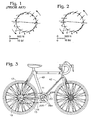
- a preferred embodiment of the present invention consists of a replacement chainring-driving mechanism for installation in a conventional bicycle 9 using an existing conventional crankshaft 34 mounted in a conventional crankshaft bearing housing or bottom bracket 32 (also shown for orientation purposes are a seat tube 40 and a down tube 42 that are part of a frame of the bicycle 9).
- a conventional chainring 14 drives an endless chain 15 to drive the rear wheel 17 in a conventional manner, such as through a set of cogs mounted on the rear wheel 17 and of which one may be selected by the use of a derailleur 19.
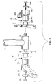
- crankshaft 34 fits snugly into a mating female receptacle at the axis of rotation of a pedal lever, or crank arm.
- a right sided crankshaft adapter 10R and a left sided crankshaft adapter 10L each are fitted over the respective squared male end of the crankshaft 34 via a mating square female receptacle 35 in each adapter 10R or 10L.
- each crankshaft adapter 10R or 10L also incorporates a cylindrical bearing surface 12, and a respective radially extending inner flange 11 or 13.
- the left inner flange 13 only need extend beyond the bearing surface 12 far enough to act as a barrier to prevent inward migration of a clutch bearing 16L, that rides on the bearing surface, during use.
- the inner flange 11 of the right side crankshaft adapter 10R is substantially larger in diameter to function also as a chainwheel support bracket to which is attached one or more conventional chainrings 14 using conventional chainring attachment devices (not shown).
- Each said bearing surface 12 is appropriately sized, shaped and hardened to accept either a right sided one-way clutch 16R or left sided one-way clutch 16L (Torrington drawn cup roller clutch, RCB 30, for example, available from The Torrington Company, Torrington, Connecticut).
- Each said right sided one-way clutch or left sided one-way clutch is affixed (for example, by a pressed fit) to the fulcrum or inner end of a right sided crank arm 20R or left sided crank arm 20L, securely enough to transmit the torque generated in the crank arm to the clutch.
- At the other end of each said crank arm is a means for accepting any conventional pedal (not shown) that incorporates a means of attaching the pedal to the rider's foot.
- crank arm and clutch is then slipped onto the bearing surface found on either said right or left crankshaft adapter (10R, 10L) in such a manner as to cause each of said pedal levers to drive the crankshaft 34 when rotated clockwise (forward) when viewed from the right, as indicated by the arrows 36 and 38, and to rotate freely with respect to the crankshaft 34 when rotated in the opposite direction.
- a right endcap 24R and left endcap 24L are each designed to securely hold each respective crankshaft adapter 10R and 10L onto the crankshaft 34 and each said crank arm and one-way clutch assembly to each said crankshaft adapter when a right threaded bolt 28R or left threaded bolt 28L is passed through a hole in the center of each endcap 24R, 24L and screwed tightly into the threaded hole present in the respective end of the crankshaft 34. Therefore, a drive mechanism incorporating the present invention can be attached to a conventional bicycle in exactly the same way as a conventional pedal system, is simple, and weighs barely more than a conventional pedal system.
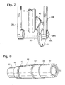
- An alternative embodiment of the invention shown in Fig. 8, includes a crankshaft 44.
- crankshaft 44 counterparts of the radially-extending inner flanges 11 and 13 incorporated in adapters 10L and 10R of the previously described embodiment of the invention are incorporated in the crankshaft 44, as indicated at 46 and 48.
- the cylindrical bearing surfaces required by the one-way clutches 16R and 16L are incorporated in the crankshaft 44, at 50, and the bottom bracket bearing surfaces are shown at 52.
- an alternative method of attaching the endcaps would be required, such as screwing directly into the end of the crankshaft at 54.
- an alternative method of attaching a chainring support bracket to the crankshaft would be required, such as using a collar with set screw (not shown).
- the power transfer mechanism of the present invention can be used in a manner identical to conventional pedaling systems as long as enough "forward" force is maintained on each pedal during the recovery phase to maintain the circular pedaling motion. This requires that the pedal must be attached to the rider's foot in some fashion to transmit these forces. If enough force is not applied to lift the pedal at the same rate as the rate of rotation of the other pedal, the pedals will instantaneously become “out of synch,” making further pedaling difficult until corrected. This feature will, with continued use, cause the rider to develop strength and endurance in the muscles required to maintain positive pressure on the pedal during the entire 360° arc of the pedals for long periods of time. This absolutely eliminates and prevents any losses due to weighting of the pedal on the upstroke, improving power output substantially.
- Another advantage of this invention is that it allows the elimination of the one-way clutch (freewheel) on the driven wheel 17.
- a mechanism incorporating this invention will operate well with or without a freewheel on the driven wheel. Elimination of the freewheel on the driven wheel would allow for reduced overall weight of the bicycle and, at the same time, allow for shifting a derailleur shifting mechanism 19 while coasting, as long as the bicycle is moving forward, since the chain would rotate continuously, even while coasting.
- the rider may also use a reciprocating up and down motion as shown in Fig. 6, rather than the traditional circular pedaling motion. It is anticipated that most riders will not use this motion except, perhaps, under very unusual circumstances, such as climbing very steep hills.
- pedaling in a reciprocating fashion the pedals will be depressed in an alternating fashion through a vertical height of about 6-8 inches, comprising an arc of about 45-60 degrees. While one pedal is being depressed the other will be returned to the proper position for the next application of power.
- the movement of the feet would be in an alternating fashion similar to climbing stairs, while movement of the pedals will be in the sector of the circle of pedal rotation where gravity best assists the rider in applying force.
- Another advantage of the device is that it allows the rider to raise both feet at the same time when coasting down hills in order to reduce frontal area, improving aerodynamic efficiency as illustrated in Fig. 7.
- crankshaft 34 and crankshaft adapters 10L and 10R can be connected together in another fashion or manufactured as a single entity as illustrated in Fig. 8.
- a different sized bottom bracket bearing housing 32 could be used on new design bicycle frames to incorporate other crankshaft designs.
- Multiple riders can be connected in series as usually seen in tandem bicycles.
- this invention can be used in a variety of human powered machines other than bicycles, such as aircraft, watercraft, and electrical generators.
- FIG. 9 An electrical generator arrangement is shown in schematic exploded form in Fig. 9, where a rotary element 56 of an electrical generator may be fixed to the crankshaft 34, driven by crank arms 20R and 20L through one-way clutches 16R and 16L and crankshaft adaptors 10R and 10L, while the remainder 64 of the generator is attached to or incorporated into the frame of the machine.
Landscapes
- Engineering & Computer Science (AREA)
- Chemical & Material Sciences (AREA)
- Combustion & Propulsion (AREA)
- Transportation (AREA)
- Mechanical Engineering (AREA)
- Connection Of Motors, Electrical Generators, Mechanical Devices, And The Like (AREA)
- Transmission Devices (AREA)
- Shafts, Cranks, Connecting Bars, And Related Bearings (AREA)
- Lock And Its Accessories (AREA)
- Mechanical Control Devices (AREA)
- Steering Devices For Bicycles And Motorcycles (AREA)
Claims (9)
- Kraftübertragungsmechanismus für die Verwendung bei einer Antriebsverbindung mit einer Kraftausgangsvorrichtung an einer vom Menschen angetriebenen Maschine, mit einem konventionellen Fahrradrahmen, welcher ein konventionelles Kurbelwellenlagergehäuse (32) definiert, wobei der Kraftübertragungsmechanismus aufweist:(a) eine einzelne konventionelle Kurbelwelle (34), welche zur Rotation um eine Achse montiert ist und ein Paar von Enden aufweist; und(b) wenigstens ein Rotationsantriebselement (11), welches an der genannten konventionellen Kurbelwelle (34) zur Rotation mit dieser befestigt ist, sowie zur Übertragung von Kraft von der genannten Kurbelwelle zu der genannten Kraftausgangsvorrichtung; und(c) ein Paar von Pedalkurbelarmen (20L, 20R), welche jeweils unabhängig über einen unbegrenzten Rotationswinkel bezüglich des genannten Rahmens und um die genannte Achse rotierbar sind; und(d) ein Paar von unbegrenzt variablen Einwegkupplungen (16L, 16R), wobei eine jeweilige der genannten Einwegkupplungen dem jeweiligen genannten Kurbelarm (20L, 20R) zugeordnet und an der genannten konventionellen Kurbelwelle (34) anstelle eines konventionellen Kurbelarmes angebracht durch einen jeweiligen Kurbelwellenadapter (10L, 10R) sind, welcher so konfiguriert ist, dass er an einem jeweiligen Ende der konventionellen Kurbelwelle (34) anzubringen ist, wodurch jeder genannte Kurbelarm unabhängig mit der genannten Kurbelwelle antriebsmäßig verbunden ist, um die genannte Kurbelwelle in einer Vorwärtsrichtung bei einer Geschwindigkeit zu bewegen, welche wenigstens gleich der Rotationsgeschwindigkeit jedes genannten Kurbelarmes in Folge der Bewegung eines der genannten Kurbelarme in der Vorwärtsrichtung ist, wobei die Kurbelwelle (34) frei bleibt, um in der genannten Vorwärtsrichtung bezüglich jedes der genannten Kurbelarme zu rotieren.
- Kraftantriebsmechanismus nach Anspruch 1, wobei der genannte Mechanismus frei von irgendwelchen Antriebsverbindungen ist, abgesehen von den genannten unbegrenzt variablen Einwegkupplungen (16L, 16R) und den genannten Kurbelwellenadaptern (10L, 10R) zwischen jedem der genannten Kurbelarme und der genannten Kurbelwelle, und wobei jeder der genannten Kurbelarme (20L, 20R) somit jederzeit frei ist, sich entgegen der genannten Vorwärtsrotationsrichtung bezüglich der genannten konventionellen Kurbelwelle (34) zu bewegen.
- Kraftübertragungsmechanismus nach Anspruch 1 oder 2, wobei der genannte Mechanismus frei ist von Elementen außer den genannten Einwegkupplungen (16L, 16R) und den genannten Kurbelwellenadaptern (10L, 10R), welche die Rotation der genannten Kurbelarme (20L, 20R) bezüglich der genannten Kurbelwelle beschränken.
- Kraftübertragungsmechanismus nach einem der Ansprüche 1 bis 3, bei welchem die Kraftausgangsvorrichtung ein elektrischer Generator ist, wobei das genannte Rotationsantriebselement antriebsmäßig mit einem Motor (56) des genannten elektrischen Generators verbunden ist, und wobei ein anderer Teil (64) des Generators so konfiguriert ist, dass er fest an dem Rahmen der Maschine angebracht ist.
- Kraftübertragungsmechanismus nach einem der Ansprüche 1 bis 3, in Kombination mit der genannten, vom Menschen angetriebenen Maschine, wobei die genannte vom Menschen angetriebene Maschine ein konventionelles Fahrrad ist.
- Kraftübertragungsmechanismus nach einem der Ansprüche 1 bis 3, bei welchem die genannte, vom Menschen angetriebene Maschine ein konventionelles Fahrrad ist.
- Kraftübertragungsmechanismus nach einem der Ansprüche 1, 2, 3, 5 und 6, welcher weiterhin ein flexibles Antriebsglied einschließt, welches mit dem genannten Rotationsantriebselement (11) in Eingriff steht, um dadurch angetrieben zu werden.
- Kraftübertragungsmechanismus nach Anspruch 7, bei welchem das genannte Rotationsantriebselement (11) einen Kettenring (14) aufweist und das genannte flexible Antriebsglied, welches mit diesem in Eingriff steht, eine endlose Kette ist.
- Verwendung eines Gerätes nach einem der vorhergehenden Ansprüche, wobei der Benutzer gezwungen ist, jeden der Pedalhebelarme unmittelbar während jeder Aufwärtsphase der Rotation des Hebelarmes anzuheben, während er kontinuierlich vorwärts über aufeinanderfolgende volle Umdrehungen der Pedalhebelarme in die Pedale tritt, um die Stärke und Widerstandskraft der Muskeln des Benutzers zu verbessern.
Applications Claiming Priority (3)
| Application Number | Priority Date | Filing Date | Title |
|---|---|---|---|
| US819165 | 1997-03-17 | ||
| US08/819,165 US5860329A (en) | 1997-03-17 | 1997-03-17 | Pedaling mechanism for bicycles and the like |
| PCT/US1998/005089 WO1998041441A1 (en) | 1997-03-17 | 1998-03-12 | Improved pedaling mechanism for bicycles and the like |
Publications (3)
| Publication Number | Publication Date |
|---|---|
| EP0968115A1 EP0968115A1 (de) | 2000-01-05 |
| EP0968115A4 EP0968115A4 (de) | 2000-08-30 |
| EP0968115B1 true EP0968115B1 (de) | 2006-08-16 |
Family
ID=25227375
Family Applications (1)
| Application Number | Title | Priority Date | Filing Date |
|---|---|---|---|
| EP98910421A Expired - Lifetime EP0968115B1 (de) | 1997-03-17 | 1998-03-12 | Trettkurbelkomplett für fahrräder und dergleichen |
Country Status (8)
| Country | Link |
|---|---|
| US (1) | US5860329A (de) |
| EP (1) | EP0968115B1 (de) |
| JP (1) | JP3530197B2 (de) |
| AT (1) | ATE336416T1 (de) |
| AU (1) | AU747397B2 (de) |
| CA (1) | CA2283923C (de) |
| DE (1) | DE69835586T2 (de) |
| WO (1) | WO1998041441A1 (de) |
Families Citing this family (39)
| Publication number | Priority date | Publication date | Assignee | Title |
|---|---|---|---|---|
| US5984335A (en) * | 1997-10-14 | 1999-11-16 | Merida Industry Co., Ltd | Crank assembly for an electrical bicycle |
| US6913560B2 (en) * | 2001-09-26 | 2005-07-05 | Brunswick Corporation | Stationary bike |
| EP1331167A1 (de) * | 2002-01-25 | 2003-07-30 | Marco Catarinelli | Umkehreinrichtung der Pedalwegdrehung für Fahrräder |
| DE60301883T2 (de) * | 2002-06-03 | 2006-07-27 | Urs Tanner | Kurbel mit freilauf |
| DE10358007B3 (de) * | 2003-12-11 | 2005-09-01 | Wang, Chien-Kuo, Hsinchuang | Fahrrad mit zwei Pedalbetätigungs-Betriebsarten |
| US7487987B2 (en) | 2004-01-05 | 2009-02-10 | Ningbo Landsurf Sports Equipment Co. Ltd. | User-propelled riding toys with simultaneous pedal recovery system |
| US7047817B2 (en) * | 2004-02-17 | 2006-05-23 | Forza, Inc. | Load measurement apparatus and methods utilizing torque sensitive link for pedal powered devices |
| KR100584525B1 (ko) * | 2004-02-25 | 2006-05-30 | 전지훈 | 자전거의 크랭크 구조 |
| WO2006045150A1 (en) * | 2004-10-26 | 2006-05-04 | Robert Masterton Smith | Improvements in drive mechanisms for human-powered machines |
| US7727125B2 (en) * | 2004-11-01 | 2010-06-01 | Day Franklin J | Exercise machine and method for use in training selected muscle groups |
| US7530932B2 (en) * | 2004-11-29 | 2009-05-12 | A.A.R.M.-1 Llc | Upper-body exercise cycle |
| US7607370B2 (en) * | 2005-08-16 | 2009-10-27 | Franklin J. Day | Crank with clutch and coupler |
| JP4847156B2 (ja) * | 2006-02-28 | 2011-12-28 | 株式会社シマノ | 自転車用クランク軸組立体 |
| US7507188B2 (en) * | 2006-04-20 | 2009-03-24 | Nurre Christopher G | Rehab cycle crank |
| WO2007133681A2 (en) * | 2006-05-11 | 2007-11-22 | Fallbrook Technologies Inc. | Continuously variable drivetrain |
| USD571873S1 (en) | 2007-03-26 | 2008-06-24 | Five Giri, Inc. | Exercise cycle frame |
| USD575838S1 (en) | 2007-03-26 | 2008-08-26 | Five Girl, Inc. | Exercise cycle frame and fork |
| USD578583S1 (en) | 2007-03-26 | 2008-10-14 | Five Giri, Inc. | Crank arm |
| US7758475B2 (en) * | 2007-03-26 | 2010-07-20 | Five Girl, Inc. | Upper body exercise cycle |
| US8517405B2 (en) * | 2007-09-10 | 2013-08-27 | Hui Yan | Human powered vehicle with two reciprocal pedals |
| JP5166141B2 (ja) * | 2008-07-04 | 2013-03-21 | アイデス株式会社 | 子供用乗物 |
| US20100167881A1 (en) * | 2008-12-31 | 2010-07-01 | Day Franklin J | Crank mechanism and bicycle incorporating same |
| EP2275330A1 (de) * | 2009-07-15 | 2011-01-19 | Igor Torubarov | Aggregat für ein Elektrorad |
| US20110081715A1 (en) * | 2009-10-02 | 2011-04-07 | Biomerieux Inc. | Single layer plastic test sample culture bottle |
| US8991845B2 (en) | 2011-05-16 | 2015-03-31 | Henry Chong | Vehicular system having user-interface assembly |
| US9358738B2 (en) | 2012-10-31 | 2016-06-07 | Biomerieux, Inc. | Aseptic blow, fill and seal methods of fabricating test sample containers and associated systems and containers |
| US9428287B2 (en) | 2012-10-31 | 2016-08-30 | BIOMéRIEUX, INC. | Methods of fabricating test sample containers by applying barrier coatings after sealed container sterilization |
| US8904905B2 (en) * | 2012-12-11 | 2014-12-09 | Shimano Inc. | Crank detachable holder |
| US9523110B2 (en) | 2013-02-15 | 2016-12-20 | Biomerieux, Inc. | Culture containers with internal top coating over gas barrier coating and associated methods |
| USD737960S1 (en) | 2013-04-24 | 2015-09-01 | BIOMéRIEUX, INC. | Adapter cap with needle bore having flat internal surfaces |
| KR102155813B1 (ko) | 2013-04-24 | 2020-09-14 | 바이오메리욱스, 인코포레이티드. | 샘플 수집 용기용 어댑터 캡 및 코어 핀을 갖는 연관된 몰드 및 이와 관련된 방법 |
| GR20150100380A (el) * | 2015-08-31 | 2017-04-10 | Αντωνιος Κωνσταντινου Μαστροκαλος | Μετατροπεας δυναμικης σε περιστροφικη κινηση αλυσοδετου πλαγιωστηρα |
| US10322767B2 (en) | 2016-01-24 | 2019-06-18 | Costel Dragomir | Carry-on foldable stepper scooter |
| FR3054372A1 (fr) * | 2016-07-21 | 2018-01-26 | St Microelectronics Tours Sas | Montage de composants electroniques |
| US10850800B2 (en) | 2017-02-22 | 2020-12-01 | John C. Schmertz | Bicycle drivetrain |
| US10722414B2 (en) * | 2017-11-01 | 2020-07-28 | Alex Bush | Exercising device |
| CN108163125A (zh) * | 2017-12-30 | 2018-06-15 | 天津市来悦科技有限公司 | 一种轮盘的曲柄驱动机构 |
| EP3753829B1 (de) | 2018-03-05 | 2022-12-14 | Honda Motor Co., Ltd. | Messvorrichtung für übungsausmass für fahrräder und fahrrad |
| KR102034744B1 (ko) | 2019-07-29 | 2019-10-21 | 백성구 | 자전거 구동장치 |
Family Cites Families (27)
| Publication number | Priority date | Publication date | Assignee | Title |
|---|---|---|---|---|
| US302090A (en) * | 1884-07-15 | bernhard | ||
| US88574A (en) * | 1869-04-06 | Improved velocipede | ||
| US433720A (en) * | 1890-08-05 | chace | ||
| US241395A (en) * | 1881-05-10 | Velocipede | ||
| US611764A (en) * | 1898-10-04 | Hand and chain operated tricycle | ||
| US87769A (en) * | 1869-03-16 | Improved velocipede | ||
| US328353A (en) * | 1885-10-13 | Bicycle | ||
| US564408A (en) * | 1896-07-21 | Tricycle | ||
| US483495A (en) * | 1892-09-27 | Tricycle | ||
| US1058123A (en) * | 1912-05-06 | 1913-04-08 | William A Whitaker | Propelling device of polycycles. |
| US3820820A (en) * | 1972-04-03 | 1974-06-28 | J Kutz | Pedal drive |
| US3877724A (en) * | 1973-10-01 | 1975-04-15 | Zenas E Chase | Variable torque drive mechanism for bicycles |
| US3884317A (en) * | 1974-03-05 | 1975-05-20 | Augustus B Kinzel | Electrically powered cycle |
| US3994509A (en) * | 1976-01-28 | 1976-11-30 | Schaeffer Jerome E | Propulsion means for wheelchairs |
| FR2460834A1 (fr) * | 1979-04-04 | 1981-01-30 | Beaumont Maurice | Pedalier a manivelles amovibles pour tous vehicules ou appareils utilisant ce type de transmission |
| US4379566A (en) * | 1981-01-26 | 1983-04-12 | Creative Motion Industries, Inc. | Operator powered vehicle |
| US4453729A (en) * | 1982-09-20 | 1984-06-12 | Lucken Wesley O | Occupant propellable wheelchair |
| AU2925784A (en) * | 1983-06-17 | 1984-12-20 | Paraid Ltd. | Hand operated wheel propulsion device suitable for wheel chairs |
| US4639007A (en) * | 1985-09-19 | 1987-01-27 | Fred W. Wagenhals | Exercise vehicle |
| US4657273A (en) * | 1986-01-08 | 1987-04-14 | Southeastern Research And Development, Inc. | Two-wheeled cycle |
| US4762332A (en) * | 1986-06-17 | 1988-08-09 | Byung D. Yim | Wheel chair |
| US5184837A (en) * | 1988-02-01 | 1993-02-09 | Alexander Tracey S | Wheelchair |
| US4925200A (en) * | 1989-06-01 | 1990-05-15 | Jones Micheal D | Tricycle drive mechanism |
| US5088340A (en) * | 1991-03-27 | 1992-02-18 | Seol Marn T | Multipurpose transmission mechanism for bicycles |
| US5228709A (en) * | 1992-09-10 | 1993-07-20 | Kung-Hsiung Wu | Wheelchair driving mechanism |
| US5390773A (en) * | 1993-12-06 | 1995-02-21 | Proia; Cataldo | Non-slip bicycle clutch |
| JP3028345U (ja) | 1995-07-07 | 1996-09-03 | 治男 若井 | 自転車 |
-
1997
- 1997-03-17 US US08/819,165 patent/US5860329A/en not_active Expired - Lifetime
-
1998
- 1998-03-12 AU AU64666/98A patent/AU747397B2/en not_active Ceased
- 1998-03-12 DE DE69835586T patent/DE69835586T2/de not_active Expired - Lifetime
- 1998-03-12 CA CA002283923A patent/CA2283923C/en not_active Expired - Fee Related
- 1998-03-12 WO PCT/US1998/005089 patent/WO1998041441A1/en not_active Ceased
- 1998-03-12 EP EP98910421A patent/EP0968115B1/de not_active Expired - Lifetime
- 1998-03-12 JP JP54066598A patent/JP3530197B2/ja not_active Expired - Fee Related
- 1998-03-12 AT AT98910421T patent/ATE336416T1/de not_active IP Right Cessation
Also Published As
| Publication number | Publication date |
|---|---|
| AU747397B2 (en) | 2002-05-16 |
| WO1998041441A1 (en) | 1998-09-24 |
| CA2283923A1 (en) | 1998-09-24 |
| CA2283923C (en) | 2005-06-14 |
| US5860329A (en) | 1999-01-19 |
| EP0968115A4 (de) | 2000-08-30 |
| DE69835586D1 (de) | 2006-09-28 |
| JP2000510562A (ja) | 2000-08-15 |
| DE69835586T2 (de) | 2007-08-09 |
| JP3530197B2 (ja) | 2004-05-24 |
| ATE336416T1 (de) | 2006-09-15 |
| EP0968115A1 (de) | 2000-01-05 |
| AU6466698A (en) | 1998-10-12 |
Similar Documents
| Publication | Publication Date | Title |
|---|---|---|
| EP0968115B1 (de) | Trettkurbelkomplett für fahrräder und dergleichen | |
| US20070228687A1 (en) | Bicycle propulsion mechanism | |
| US8602434B2 (en) | Double chainring drivetrain | |
| US6840136B1 (en) | Pedal drive mechanism | |
| US4735430A (en) | Racing bicycle having a continuously variable traction drive | |
| US5419572A (en) | Reciprocating bicycle drive | |
| US5551718A (en) | Pedal mechanism for cycle and exercise equipment | |
| CN101410290B (zh) | 用于自行车的传输系统 | |
| US5765847A (en) | Pedal mechanism for cycle and exercise equipment | |
| US6352131B1 (en) | Bicycle's power train | |
| EP3980323A1 (de) | Elektrisch unterstützte pedalzyklen | |
| US20030173755A1 (en) | Bicycle drive mechanism | |
| US5918894A (en) | Pedal mechanism for cycle and exercise equipment | |
| WO2022023774A1 (en) | Electrically- assisted pedal cycles | |
| KR100374294B1 (ko) | 적어도 2개의 휠이 구비된 인력에 의해 구동되는 수송체 | |
| US8632089B1 (en) | Mechanism for converting reciprocal motion to rotary motion | |
| RU95109866A (ru) | Устройство переднего привода для велосипеда | |
| WO2000063066A1 (en) | Hand and pedal driving device | |
| US5964472A (en) | Independent pedaling system for tandem bicycles | |
| GB2359285A (en) | Drive apparatus for self-propelled velocipede | |
| US20040150185A1 (en) | Front wheel drive handlebar for use with bicycles | |
| CN213036007U (zh) | 链轮组件和两轮车 | |
| CN120963905A (zh) | 转向传动机构及双动力自行车 | |
| RU2051833C1 (ru) | Привод велосипеда суровцева | |
| EP3393899B1 (de) | Zyklus und antriebsmechanismus dafür |
Legal Events
| Date | Code | Title | Description |
|---|---|---|---|
| PUAI | Public reference made under article 153(3) epc to a published international application that has entered the european phase |
Free format text: ORIGINAL CODE: 0009012 |
|
| 17P | Request for examination filed |
Effective date: 19991018 |
|
| AK | Designated contracting states |
Kind code of ref document: A1 Designated state(s): AT BE CH DE DK ES FI FR GB GR IE IT LI LU MC NL PT SE |
|
| A4 | Supplementary search report drawn up and despatched |
Effective date: 20000719 |
|
| AK | Designated contracting states |
Kind code of ref document: A4 Designated state(s): AT BE CH DE DK ES FI FR GB GR IE IT LI LU MC NL PT SE |
|
| 17Q | First examination report despatched |
Effective date: 20040810 |
|
| GRAP | Despatch of communication of intention to grant a patent |
Free format text: ORIGINAL CODE: EPIDOSNIGR1 |
|
| GRAS | Grant fee paid |
Free format text: ORIGINAL CODE: EPIDOSNIGR3 |
|
| GRAA | (expected) grant |
Free format text: ORIGINAL CODE: 0009210 |
|
| AK | Designated contracting states |
Kind code of ref document: B1 Designated state(s): AT BE CH DE DK ES FI FR GB GR IE IT LI LU MC NL PT SE |
|
| PG25 | Lapsed in a contracting state [announced via postgrant information from national office to epo] |
Ref country code: NL Free format text: LAPSE BECAUSE OF FAILURE TO SUBMIT A TRANSLATION OF THE DESCRIPTION OR TO PAY THE FEE WITHIN THE PRESCRIBED TIME-LIMIT Effective date: 20060816 Ref country code: IT Free format text: LAPSE BECAUSE OF FAILURE TO SUBMIT A TRANSLATION OF THE DESCRIPTION OR TO PAY THE FEE WITHIN THE PRESCRIBED TIME-LIMIT;WARNING: LAPSES OF ITALIAN PATENTS WITH EFFECTIVE DATE BEFORE 2007 MAY HAVE OCCURRED AT ANY TIME BEFORE 2007. THE CORRECT EFFECTIVE DATE MAY BE DIFFERENT FROM THE ONE RECORDED. Effective date: 20060816 Ref country code: FI Free format text: LAPSE BECAUSE OF FAILURE TO SUBMIT A TRANSLATION OF THE DESCRIPTION OR TO PAY THE FEE WITHIN THE PRESCRIBED TIME-LIMIT Effective date: 20060816 Ref country code: AT Free format text: LAPSE BECAUSE OF FAILURE TO SUBMIT A TRANSLATION OF THE DESCRIPTION OR TO PAY THE FEE WITHIN THE PRESCRIBED TIME-LIMIT Effective date: 20060816 |
|
| REG | Reference to a national code |
Ref country code: GB Ref legal event code: FG4D |
|
| REG | Reference to a national code |
Ref country code: CH Ref legal event code: EP |
|
| REG | Reference to a national code |
Ref country code: IE Ref legal event code: FG4D |
|
| REF | Corresponds to: |
Ref document number: 69835586 Country of ref document: DE Date of ref document: 20060928 Kind code of ref document: P |
|
| PG25 | Lapsed in a contracting state [announced via postgrant information from national office to epo] |
Ref country code: SE Free format text: LAPSE BECAUSE OF FAILURE TO SUBMIT A TRANSLATION OF THE DESCRIPTION OR TO PAY THE FEE WITHIN THE PRESCRIBED TIME-LIMIT Effective date: 20061116 Ref country code: DK Free format text: LAPSE BECAUSE OF FAILURE TO SUBMIT A TRANSLATION OF THE DESCRIPTION OR TO PAY THE FEE WITHIN THE PRESCRIBED TIME-LIMIT Effective date: 20061116 |
|
| PG25 | Lapsed in a contracting state [announced via postgrant information from national office to epo] |
Ref country code: ES Free format text: LAPSE BECAUSE OF FAILURE TO SUBMIT A TRANSLATION OF THE DESCRIPTION OR TO PAY THE FEE WITHIN THE PRESCRIBED TIME-LIMIT Effective date: 20061127 |
|
| PG25 | Lapsed in a contracting state [announced via postgrant information from national office to epo] |
Ref country code: PT Free format text: LAPSE BECAUSE OF FAILURE TO SUBMIT A TRANSLATION OF THE DESCRIPTION OR TO PAY THE FEE WITHIN THE PRESCRIBED TIME-LIMIT Effective date: 20070116 |
|
| NLV1 | Nl: lapsed or annulled due to failure to fulfill the requirements of art. 29p and 29m of the patents act | ||
| ET | Fr: translation filed | ||
| PLBE | No opposition filed within time limit |
Free format text: ORIGINAL CODE: 0009261 |
|
| STAA | Information on the status of an ep patent application or granted ep patent |
Free format text: STATUS: NO OPPOSITION FILED WITHIN TIME LIMIT |
|
| 26N | No opposition filed |
Effective date: 20070518 |
|
| PG25 | Lapsed in a contracting state [announced via postgrant information from national office to epo] |
Ref country code: MC Free format text: LAPSE BECAUSE OF NON-PAYMENT OF DUE FEES Effective date: 20070331 Ref country code: IE Free format text: LAPSE BECAUSE OF NON-PAYMENT OF DUE FEES Effective date: 20070312 |
|
| PG25 | Lapsed in a contracting state [announced via postgrant information from national office to epo] |
Ref country code: GR Free format text: LAPSE BECAUSE OF FAILURE TO SUBMIT A TRANSLATION OF THE DESCRIPTION OR TO PAY THE FEE WITHIN THE PRESCRIBED TIME-LIMIT Effective date: 20061117 |
|
| PG25 | Lapsed in a contracting state [announced via postgrant information from national office to epo] |
Ref country code: LU Free format text: LAPSE BECAUSE OF NON-PAYMENT OF DUE FEES Effective date: 20070312 |
|
| PGFP | Annual fee paid to national office [announced via postgrant information from national office to epo] |
Ref country code: CH Payment date: 20140327 Year of fee payment: 17 |
|
| PGFP | Annual fee paid to national office [announced via postgrant information from national office to epo] |
Ref country code: IT Payment date: 20140324 Year of fee payment: 17 Ref country code: FR Payment date: 20140317 Year of fee payment: 17 |
|
| PGFP | Annual fee paid to national office [announced via postgrant information from national office to epo] |
Ref country code: BE Payment date: 20140328 Year of fee payment: 17 |
|
| REG | Reference to a national code |
Ref country code: CH Ref legal event code: PL |
|
| PG25 | Lapsed in a contracting state [announced via postgrant information from national office to epo] |
Ref country code: IT Free format text: LAPSE BECAUSE OF NON-PAYMENT OF DUE FEES Effective date: 20150312 |
|
| REG | Reference to a national code |
Ref country code: FR Ref legal event code: ST Effective date: 20151130 |
|
| PG25 | Lapsed in a contracting state [announced via postgrant information from national office to epo] |
Ref country code: CH Free format text: LAPSE BECAUSE OF NON-PAYMENT OF DUE FEES Effective date: 20150331 Ref country code: LI Free format text: LAPSE BECAUSE OF NON-PAYMENT OF DUE FEES Effective date: 20150331 |
|
| PG25 | Lapsed in a contracting state [announced via postgrant information from national office to epo] |
Ref country code: FR Free format text: LAPSE BECAUSE OF NON-PAYMENT OF DUE FEES Effective date: 20150331 |
|
| PGFP | Annual fee paid to national office [announced via postgrant information from national office to epo] |
Ref country code: GB Payment date: 20170327 Year of fee payment: 20 |
|
| PG25 | Lapsed in a contracting state [announced via postgrant information from national office to epo] |
Ref country code: BE Free format text: LAPSE BECAUSE OF NON-PAYMENT OF DUE FEES Effective date: 20150331 |
|
| PGFP | Annual fee paid to national office [announced via postgrant information from national office to epo] |
Ref country code: DE Payment date: 20170329 Year of fee payment: 20 |
|
| REG | Reference to a national code |
Ref country code: DE Ref legal event code: R071 Ref document number: 69835586 Country of ref document: DE |
|
| REG | Reference to a national code |
Ref country code: GB Ref legal event code: PE20 Expiry date: 20180311 |
|
| PG25 | Lapsed in a contracting state [announced via postgrant information from national office to epo] |
Ref country code: GB Free format text: LAPSE BECAUSE OF EXPIRATION OF PROTECTION Effective date: 20180311 |