EP0967946B1 - Biological microfistula tube and implantation apparatus - Google Patents
Biological microfistula tube and implantation apparatus Download PDFInfo
- Publication number
- EP0967946B1 EP0967946B1 EP97913021A EP97913021A EP0967946B1 EP 0967946 B1 EP0967946 B1 EP 0967946B1 EP 97913021 A EP97913021 A EP 97913021A EP 97913021 A EP97913021 A EP 97913021A EP 0967946 B1 EP0967946 B1 EP 0967946B1
- Authority
- EP
- European Patent Office
- Prior art keywords
- tube
- microfistula
- microfistula tube
- rod
- implantation
- Prior art date
- Legal status (The legal status is an assumption and is not a legal conclusion. Google has not performed a legal analysis and makes no representation as to the accuracy of the status listed.)
- Expired - Lifetime
Links
- 238000002513 implantation Methods 0.000 title claims abstract description 46
- 210000001519 tissue Anatomy 0.000 claims abstract description 24
- 239000000463 material Substances 0.000 claims abstract description 13
- 210000002469 basement membrane Anatomy 0.000 claims abstract description 7
- 230000000149 penetrating effect Effects 0.000 claims abstract description 5
- 230000003834 intracellular effect Effects 0.000 claims abstract description 3
- 239000011159 matrix material Substances 0.000 claims abstract description 3
- 210000002159 anterior chamber Anatomy 0.000 claims description 18
- 238000003780 insertion Methods 0.000 claims description 8
- 230000037431 insertion Effects 0.000 claims description 8
- 108010010803 Gelatin Proteins 0.000 claims description 6
- 229920000159 gelatin Polymers 0.000 claims description 6
- 239000008273 gelatin Substances 0.000 claims description 6
- 235000019322 gelatine Nutrition 0.000 claims description 6
- 235000011852 gelatine desserts Nutrition 0.000 claims description 6
- 210000002330 subarachnoid space Anatomy 0.000 claims description 6
- 210000003462 vein Anatomy 0.000 claims description 5
- 230000003511 endothelial effect Effects 0.000 claims description 4
- 210000001328 optic nerve Anatomy 0.000 claims description 4
- 210000001585 trabecular meshwork Anatomy 0.000 claims description 4
- 102000008186 Collagen Human genes 0.000 claims description 3
- 108010035532 Collagen Proteins 0.000 claims description 3
- 229920001436 collagen Polymers 0.000 claims description 3
- 238000003825 pressing Methods 0.000 claims description 3
- WFKWXMTUELFFGS-UHFFFAOYSA-N tungsten Chemical compound [W] WFKWXMTUELFFGS-UHFFFAOYSA-N 0.000 claims description 3
- 229910052721 tungsten Inorganic materials 0.000 claims description 3
- 239000010937 tungsten Substances 0.000 claims description 3
- 238000000034 method Methods 0.000 description 28
- 210000004027 cell Anatomy 0.000 description 13
- 239000012530 fluid Substances 0.000 description 9
- 210000004087 cornea Anatomy 0.000 description 8
- 229910001220 stainless steel Inorganic materials 0.000 description 8
- 239000010935 stainless steel Substances 0.000 description 8
- 230000037361 pathway Effects 0.000 description 7
- 230000033001 locomotion Effects 0.000 description 5
- 230000015572 biosynthetic process Effects 0.000 description 4
- 210000002889 endothelial cell Anatomy 0.000 description 4
- 230000008569 process Effects 0.000 description 4
- 206010016717 Fistula Diseases 0.000 description 3
- 238000010521 absorption reaction Methods 0.000 description 3
- 230000003890 fistula Effects 0.000 description 3
- 239000007943 implant Substances 0.000 description 3
- 230000035515 penetration Effects 0.000 description 3
- 230000029663 wound healing Effects 0.000 description 3
- 208000010412 Glaucoma Diseases 0.000 description 2
- 238000006243 chemical reaction Methods 0.000 description 2
- 238000011161 development Methods 0.000 description 2
- 230000018109 developmental process Effects 0.000 description 2
- 230000000694 effects Effects 0.000 description 2
- 210000002919 epithelial cell Anatomy 0.000 description 2
- 230000002349 favourable effect Effects 0.000 description 2
- 210000002950 fibroblast Anatomy 0.000 description 2
- BASFCYQUMIYNBI-UHFFFAOYSA-N platinum Chemical compound [Pt] BASFCYQUMIYNBI-UHFFFAOYSA-N 0.000 description 2
- 230000035755 proliferation Effects 0.000 description 2
- 206010016654 Fibrosis Diseases 0.000 description 1
- 208000005422 Foreign-Body reaction Diseases 0.000 description 1
- 208000032984 Intraoperative Complications Diseases 0.000 description 1
- 208000031481 Pathologic Constriction Diseases 0.000 description 1
- 239000004698 Polyethylene Substances 0.000 description 1
- 206010052428 Wound Diseases 0.000 description 1
- 208000027418 Wounds and injury Diseases 0.000 description 1
- 230000002411 adverse Effects 0.000 description 1
- 230000009286 beneficial effect Effects 0.000 description 1
- 239000000560 biocompatible material Substances 0.000 description 1
- 239000012620 biological material Substances 0.000 description 1
- 210000000845 cartilage Anatomy 0.000 description 1
- 238000004132 cross linking Methods 0.000 description 1
- 201000010099 disease Diseases 0.000 description 1
- 208000037265 diseases, disorders, signs and symptoms Diseases 0.000 description 1
- 210000003027 ear inner Anatomy 0.000 description 1
- 210000003060 endolymph Anatomy 0.000 description 1
- 210000000887 face Anatomy 0.000 description 1
- 230000004761 fibrosis Effects 0.000 description 1
- 239000011521 glass Substances 0.000 description 1
- PCHJSUWPFVWCPO-UHFFFAOYSA-N gold Chemical compound [Au] PCHJSUWPFVWCPO-UHFFFAOYSA-N 0.000 description 1
- 210000003128 head Anatomy 0.000 description 1
- 201000009941 intracranial hypertension Diseases 0.000 description 1
- 230000004410 intraocular pressure Effects 0.000 description 1
- 230000007774 longterm Effects 0.000 description 1
- 238000012986 modification Methods 0.000 description 1
- 230000004048 modification Effects 0.000 description 1
- 230000003287 optical effect Effects 0.000 description 1
- 210000004049 perilymph Anatomy 0.000 description 1
- 230000004962 physiological condition Effects 0.000 description 1
- 229910052697 platinum Inorganic materials 0.000 description 1
- 229920003229 poly(methyl methacrylate) Polymers 0.000 description 1
- -1 polyethylene Polymers 0.000 description 1
- 229920000573 polyethylene Polymers 0.000 description 1
- 239000004926 polymethyl methacrylate Substances 0.000 description 1
- 210000001747 pupil Anatomy 0.000 description 1
- 230000004044 response Effects 0.000 description 1
- 231100000241 scar Toxicity 0.000 description 1
- 210000003786 sclera Anatomy 0.000 description 1
- 239000000126 substance Substances 0.000 description 1
- 238000001356 surgical procedure Methods 0.000 description 1
- GUVRBAGPIYLISA-UHFFFAOYSA-N tantalum atom Chemical compound [Ta] GUVRBAGPIYLISA-UHFFFAOYSA-N 0.000 description 1
- 230000002123 temporal effect Effects 0.000 description 1
- 230000008719 thickening Effects 0.000 description 1
- 210000000626 ureter Anatomy 0.000 description 1
- 210000003708 urethra Anatomy 0.000 description 1
- XLYOFNOQVPJJNP-UHFFFAOYSA-N water Substances O XLYOFNOQVPJJNP-UHFFFAOYSA-N 0.000 description 1
Images







Classifications
-
- A—HUMAN NECESSITIES
- A61—MEDICAL OR VETERINARY SCIENCE; HYGIENE
- A61F—FILTERS IMPLANTABLE INTO BLOOD VESSELS; PROSTHESES; DEVICES PROVIDING PATENCY TO, OR PREVENTING COLLAPSING OF, TUBULAR STRUCTURES OF THE BODY, e.g. STENTS; ORTHOPAEDIC, NURSING OR CONTRACEPTIVE DEVICES; FOMENTATION; TREATMENT OR PROTECTION OF EYES OR EARS; BANDAGES, DRESSINGS OR ABSORBENT PADS; FIRST-AID KITS
- A61F9/00—Methods or devices for treatment of the eyes; Devices for putting in contact-lenses; Devices to correct squinting; Apparatus to guide the blind; Protective devices for the eyes, carried on the body or in the hand
- A61F9/007—Methods or devices for eye surgery
-
- A—HUMAN NECESSITIES
- A61—MEDICAL OR VETERINARY SCIENCE; HYGIENE
- A61F—FILTERS IMPLANTABLE INTO BLOOD VESSELS; PROSTHESES; DEVICES PROVIDING PATENCY TO, OR PREVENTING COLLAPSING OF, TUBULAR STRUCTURES OF THE BODY, e.g. STENTS; ORTHOPAEDIC, NURSING OR CONTRACEPTIVE DEVICES; FOMENTATION; TREATMENT OR PROTECTION OF EYES OR EARS; BANDAGES, DRESSINGS OR ABSORBENT PADS; FIRST-AID KITS
- A61F9/00—Methods or devices for treatment of the eyes; Devices for putting in contact-lenses; Devices to correct squinting; Apparatus to guide the blind; Protective devices for the eyes, carried on the body or in the hand
- A61F9/007—Methods or devices for eye surgery
- A61F9/00781—Apparatus for modifying intraocular pressure, e.g. for glaucoma treatment
-
- A—HUMAN NECESSITIES
- A61—MEDICAL OR VETERINARY SCIENCE; HYGIENE
- A61L—METHODS OR APPARATUS FOR STERILISING MATERIALS OR OBJECTS IN GENERAL; DISINFECTION, STERILISATION OR DEODORISATION OF AIR; CHEMICAL ASPECTS OF BANDAGES, DRESSINGS, ABSORBENT PADS OR SURGICAL ARTICLES; MATERIALS FOR BANDAGES, DRESSINGS, ABSORBENT PADS OR SURGICAL ARTICLES
- A61L31/00—Materials for other surgical articles, e.g. stents, stent-grafts, shunts, surgical drapes, guide wires, materials for adhesion prevention, occluding devices, surgical gloves, tissue fixation devices
- A61L31/005—Ingredients of undetermined constitution or reaction products thereof
-
- A—HUMAN NECESSITIES
- A61—MEDICAL OR VETERINARY SCIENCE; HYGIENE
- A61L—METHODS OR APPARATUS FOR STERILISING MATERIALS OR OBJECTS IN GENERAL; DISINFECTION, STERILISATION OR DEODORISATION OF AIR; CHEMICAL ASPECTS OF BANDAGES, DRESSINGS, ABSORBENT PADS OR SURGICAL ARTICLES; MATERIALS FOR BANDAGES, DRESSINGS, ABSORBENT PADS OR SURGICAL ARTICLES
- A61L31/00—Materials for other surgical articles, e.g. stents, stent-grafts, shunts, surgical drapes, guide wires, materials for adhesion prevention, occluding devices, surgical gloves, tissue fixation devices
- A61L31/04—Macromolecular materials
- A61L31/043—Proteins; Polypeptides; Degradation products thereof
- A61L31/044—Collagen
-
- A—HUMAN NECESSITIES
- A61—MEDICAL OR VETERINARY SCIENCE; HYGIENE
- A61M—DEVICES FOR INTRODUCING MEDIA INTO, OR ONTO, THE BODY; DEVICES FOR TRANSDUCING BODY MEDIA OR FOR TAKING MEDIA FROM THE BODY; DEVICES FOR PRODUCING OR ENDING SLEEP OR STUPOR
- A61M27/00—Drainage appliance for wounds or the like, i.e. wound drains, implanted drains
Definitions
- This invention relates to a microfistula tube for the creation of microfistulae within the body, to be used for example to drain unwanted aqueous fluid, and an apparatus for the insertion into the body of a microfistula tube.
- the microfistula tube is used for drainage of excess fluid in the eye.
- Existing devices for the drainage of excessive aqueous fluid within the body have been made of materials such as horse-hair, silk thread, gold foil, autologous canaliculus, tantalum wire, glass, platinum, polymethylmethacrylate, polyethylene, gelatin and autologous cartilage.
- Various devices made of these materials have been inserted, for example, in the anterior chamber of the eye under a conjunctival or scleral flap extending into the anterior subconjunctival space.
- problems frequently associated with existing devices include foreign-body reactions leading to fibroblast proliferation and sub-conjunctival fibrosis formation around the posterior exit of the drainage implant.
- existing devices require large incisions of 1 mm ⁇ 3 mm or even larger. Such incisions represent an extensive surgical injury and can lead to the formation of excessive quantities of scar tissue.
- existing fistula tubes are mainly of non-biological materials and operate in far from physiological conditions. Such a fistula tube may generate an adverse tissue response, which causes blockage of the fistula tube resulting in uncontrolled eye pressure and ultimately negates any beneficial effects. More recent developments have attempted to protect the posterior exit of the drainage tube and develop posterior shunting of aqueous fluid to an equatorial sub-Tenon's collecting device.
- WO-A-94 13234 discloses a microfistula tube for treatment of glaucoma including a duct defining a drainage canal having an inner surface, the duct being bio-compatible.
- An object of the present invention is to provide a biological microfistula tube subject to reduced rejection effects, that will lead to the formation of a microfistula for permanent or long-term aqueous fluid bypass, with minimal overdraining, and tending to impede wound healing processes and hence the closure of the drainage pathway. Further objects of the invention are to provide such a biological microfistula tube generating minimal tissue reaction, and matching outflow-resistance, to allow the control of eye pressure and reduce surgical complications. A further object of the present invention is to provide an apparatus for the implantation of the biological microfistula tube.
- a microfistula tube including:
- any suitable biocompatible material may be used, provided it permits the adherence of a basement membrane to the inner surface of the microfistula tube, and permits host endothelial or epithelial cells to grow in and coat the inner surface, while permitting minimal tissue reaction.
- the microfistula tube may be placed into a body, but will be incorporated into surrounding tissue or absorbed by the body over time.
- the biological cells - whose type will depend on the location where the microfistula tube is implanted - will provide a biological lining of the drainage pathway (i.e. microfistula) formed within the body by the microfistula tube, and inhibit the wound healing processes that would tend to occlude the drainage pathway. These cells will also reduce rejection effects.
- the biological cells which will eventually form a permanent or long-lived endothelial, epithelial or similar lining of the drainage pathway formed by the microfistula tube minimize the tendency for fibroblast proliferation and the occlusion of the pathway. Consequently a microfistula tube size smaller than has been feasible with prior art devices or techniques may be employed, thereby reducing the risk of overdraining the aqueous fluid.
- the biological cells are endothelial or trabecular meshwork cells.
- the microfistula tube is made of gelatin or collagen.
- the mechanical and absorption properties of the tube may readily be manipulated, and the microfistula tube given the required rigidity and absorption properties.
- the microfistula tube is sufficiently rigid to allow ready insertion into a living body.
- the microfistula tube is a tube with a circular cross-section.
- the outer surface of the microfistula tube tapers towards its forward end to facilitate its insertion into body tissues.
- the microfistula tube may be narrower at the forward end so that it can more easily be pushed into the relevant tissues of the body.
- the duct is provided with one or more generally rearwardly projecting barbs or a generally rearwardly projecting skirt.
- the one or more barbs or said skirt is near the forward end of said microfistula tube.
- the rearward end of said microfistula tube has thicker walls to provide improved area and strength to allow the microfistula tube to be pushed into place by pressing against the rear end of the microfistula tube.
- the rearward end of the microfistula tube has an increased outer perimeter size to prevent the microfistula tube from advancing beyond the point of implantation.
- the rear end of the microfistula tube has an increased perimeter or, when the microfistula is tubular, an increased outer diameter, both to provide a broader base against which pressure may be applied to insert the microfistula tube into body tissues, and also to prevent the microfistula tube from advancing further than the point of implantation.
- the microfistula tube is adapted to form a passage from the anterior chamber to Schlemm's canal, and has an interior diameter of between 100 and 200 ⁇ m, and a length of between 1 and 3 mm.
- the microfistula tube has an interior diameter of approximately 150 ⁇ m and a length of approximately 2 mm.
- the microfistula tube is adapted to form a passage from the anterior chamber to the anterior subconjunctival space and has an interior diameter of between 100 and 400 ⁇ m and a length of between 2 and 6 mm.
- the microfistula tube has an interior diameter of between 250 and 350 ⁇ m.
- the microfistula tube has an interior diameter of approximately 300 ⁇ m and a length of approximately 3 mm.
- microfistula tube is adapted to form a passage from the anterior chamber to the episcleral vein, with an inner diameter of between 100 and 300 ⁇ m and a length of between 7 and 14 mm.
- the microfistula tube has an inner diameter of approximately 150 ⁇ m and a length of approximately 10 mm.
- the microfistula tube is adapted to form a passage from the vitreal cavity to the subarachnoid space of the optic nerve, and has an inner diameter of between 100 and 300 ⁇ m and a length of between 3 and 12 mm.
- the microfistula tube has an inner diameter of approximately 150 ⁇ m and a length of approximately 6 mm.
- the microfistula tube may be used in optical applications to shunt aqueous fluid from the anterior chamber into Schlemm's canal, the subconjunctival space, or the episcleral vein, or from the vitreal cavity to the subarachnoid space of the optic nerve.
- the present invention also provides a microfistula tube implantation system including:
- the outer tube can be used to penetrate body tissues (for example a cornea), and the inner tube can then be used to push the microfistula tube forward and out of the forward end of the outer tube.
- the innermost rod may be moved with the inner tube until the microfistula tube is in its final position, and then the innermost rod may be withdrawn, followed by the inner tube.
- the outer tube may then be withdrawn from the body.
- microfistula tube is adapted to receive said innermost rod.
- the outer tube is a hypodermic-type tube.
- the inner tube is blunt-ended.
- the outer tube is of stainless steel.
- the inner tube is of stainless steel.
- the innermost rod is of tungsten.
- the surgical instrument is adapted to be attached to an ultramicrosurgical system.
- the surgical instrument is adapted to be manipulated by electric motors.
- the surgical instrument is adapted to deliver the microfistula tube to the required location.
- the surgical instrument is used with a microsurgical system powered by electric motors and the operational procedures are performed under an operation microscope and gonioscopic observation.
- the present invention further provides a microfistula tube implantation system including:
- the outer tube is a hypodermic-type tube.
- the outer tube is of stainless steel.
- the inner rod is of stainless steel.
- the surgical instrument is adapted to be attached to an ultramicrosurgical system.
- the surgical instrument is adapted to be manipulated by electric motors.
- a method for the implantation of a microfistula tube comprises the steps of introducing into the vicinity of a desired implantation location the implantation system of claim 22 with said microfistula tube mounted on the innermost rod, pushing the microfistula tube out of the outer tube and into a desired location by means of the inner tube, the rod moving in unison with the inner tube and the microfistula tube, withdrawing the surgical instrument from the body.
- the rod is withdrawn from the microfistula tube before the inner tube is withdrawn.
- the rod and inner tube are withdrawn into the outer tube before the inner tube, outer tube and rod are withdrawn from the body.
- the desired location is the anterior chamber.
- a further method for the implantation of a microfistula tube comprises the steps of forming said passage with said outer tube of the implantation system of claim 29 with said microfistula tube in said outer tube forward of said inner rod, advancing said microfistula tube to said implantation site with said inner rod, withdrawing said outer tube, withdrawing said inner rod, and withdrawing the surgical instrument.
- the method includes withdrawing the outer tube partially, then withdrawing said inner rod partially, followed by withdrawing said inner rod and outer tube in unison.
- the partial withdrawal of the outer tube continues until said forward of said outer tube is in the anterior chamber.
- the method includes rotating said outer tube with a reciprocating motion while forming said passage to aid said cutting of said tissue.
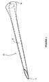
- a biological microfistula tube according to the present invention is shown generally at 10 in Figure 1.
- the microfistula tube 20 comprises a hollow tube which defines a drainage canal 15 with a forward end 12 terminating in a point to facilitate the penetration by the microfistula tube 10 of tissue and a rear end 14.
- the rear end 14 of the microfistula tube 10 has thickened walls to strengthen the microfistula tube 10, as implantation of the microfistula tube 10 will generally be performed by pushing the microfistula tube 10 into place by applying pressure to the rear end 14.
- the microfistula tube 10 is made from gelatin, as the mechanical and absorption properties of the gelatin can be manipulated by varying the degree of cross-linking and controlling the water content.
- the material can therefore be designed to have the required rigidity to withstand the implantation process, but be absorbed after a controllable period. In most instances this would be only a matter of days or weeks.
- the microfistula tube incorporates biological cells. Such cells lead to the formation of a biological lining of the drainage canal, which inhibits the wound-healing processes that would tend to occlude the drainage pathway. These cells (not shown) are either endothelial cells or ocular trabecular meshwork cells. These cells would generally line the inner surface of the microfistula tube 10, though other configurations are possible, such as incorporating the cells into the material of the microfistula tube 10.
- the microfistula tube 10 can be provided with one or more rearward pointing barbs (not shown), preferably located near the forward end 12 and on the outer surface of the microfistula tube 10. These barbs would resist the unwanted rearward movement of the microfistula tube 10 following implantation.
- the flared rear end 14 of the microfistula tube 10, and the generally tapered profile of the microfistula tube 10, will resist unwanted forward movement of the microfistula tube 10.
- the thickening of the rear end 14 of the microfistula tube 10 can be extended forward some distance to further resist unwanted forward motion of the microfistula tube 10 after implantation.
- This thickened portion of the rearward end 14 may be terminated more abruptly than shown in Figure 1, so that a substantially forward facing surface is provided for this purpose.
- the rearward pointing face 16 of the rear end 14 of the microfistula tube 10 may be recessed or otherwise adapted to receive the forward end of a surgical instrument, to facilitate implantation of the microfistula tube 10 by means of such an instrument.
- a surgical instrument according to the present invention provided with a microfistula tube 10 is shown generally at 30 in Figure 2.
- the surgical instrument 30 shown in the Figure is adapted for the implantation of the microfistula tube 10 into the eye to form a drainage pathway from the anterior chamber to the subconjunctival space.
- the microfistula tube 10 shown in the Figure includes rearward pointing barbs and a recessed base, as discussed above.
- the surgical instrument 30 comprises an outer tube 32 in the form of a hypodermic-type stainless steel tube, an inner tube 34 in the form of a blunt-ended stainless steel tube, and an innermost rod 36 made of tungsten.
- the microfistula tube 10 is shown located around the forward end 38 of the innermost rod 36.
- the innermost rod 36 may slide within the inner tube 34, and the inner tube 34 may slide within the outer tube 32.
- the outer tube 32 is adapted to penetrate the cornea, while the inner tube 34 is adapted to push the microfistula tube 10 from the outer tube 32 and into its final position.
- the innermost rod 36 is adapted to provide mechanical support during the implantation of the microfistula tube 10.
- the surgical instrument 30 In use, the surgical instrument 30 would be attached to and manipulated by means of an ultramicrosurgical system, and the operation performed under an operation microscope and gonioscopic observation. All movement would be produced by electric motor.
- the outer tube 32 is sharp at its forward end 40 to facilitate the penetration of the cornea.
- the inner tube 34 is rounded at its forward end 42, and the rear end of the microfistula tube 10 has a corresponding recess, so that the end 42 of the inner tube 34 may be received by the base of the microfistula tube 10.
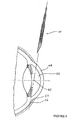
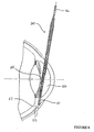
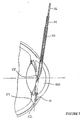
- a surgical implantation method is illustrated in Figures 3 to 8.
- the method illustrated in these figures is for the implantation of a microfistula tube to form a passage, by way of the drainage canal 15, between the anterior chamber 50 (see Figures 3 to 8) and the anterior subconjunctival space 52 (see Figures 3 to 8).
- the entry point is 2 mm anterior to the limbus on the temporal side (see Figure 3). This entry point may also be a pivot point of an ultramicrosurgical system, if such a system is used to manipulate the surgical instrument.
- the surgical instrument 30 provided with a microfistula tube 10 penetrates the cornea 48, and enters the anterior chamber 50 (see Figure 4). The insertion of the surgical instrument 30 continues until the outer tube 32 of the surgical instrument 30 reaches the centre of the pupil 55.
- the inner tube 34, the innermost rod 36, and the microfistula tube 10 are advanced further (see Figure 5), until the innermost rod 36 with the microfistula tube 10 penetrates the trabecular meshwork and sclera 57 until the tip of the microfistula tube 10 reaches the subconjunctival space 52.
- the innermost rod 36 is then withdrawn from the microfistula tube 10 ( Figure 6), and the innermost rod (now withdrawn into the inner tube 34) and the inner tube 34 are retracted into the outer tube 32 ( Figure 7).
- the microfistula tube 10 has an inner diameter of 100 ⁇ m and a length of 3 mm.
- the microfistula tube 10 can be implanted to form a passage between the anterior chamber and Schlemm's canal, in which case the inner diameter of the microfistula tube 10 is 150 ⁇ m and its length is 2 mm.
- the microfistula tube 10 forms a passage between the anterior chamber and the episcleral vein, and has an inner diameter of 150 ⁇ m and a length of 10 mm.
- a microfistula tube of inner diameter 150 ⁇ m and length 6 mm may be used to form a passage from the vitreal cavity to subarachnoid space of the optic nerve.
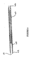
- outer tube 60 is again a hypodermic-type stainless steel tube. Unlike outer tube 32 of the embodiment illustrated in Figure 2, however, the forward end 62 of outer tube 60 is sharpened and the opening 64 at the forward end 62 faces forwardly rather than obliquely.
- Stainless steel inner rod 66 is provided within outer tube 60 and microfistula tube 68 is positioned forward of inner rod 66.
- Microfistula tube 68 will generally be substantially identical to those described above, but may lack the reinforced base of the above embodiments.
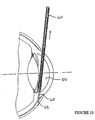
- FIGs 10 to 14 A method of implantation of a microfistula tube by means of this embodiment of the surgical instrument is illustrated in Figures 10 to 14. The method illustrated in these figures is again for the implantation of a microfistula tube between the anterior chamber and the anterior subconjunctival space.
- outer tube 60 is preferably rotated to assist the cutting of body tissues. This rotation alternates rapidly in direction so that tissue is cut by the tube 60.
- the outer tube 60 penetrates the cornea 48, and enters the anterior chamber 50.
- Inner rod 66 is not rotated during this insertion of the instrument or subsequently.
- Inner rod 66 and microfistula tube 68 are advanced with outer tube 60 until the forward end 62 of outer tube 60 reaches subconjunctival space 52 (see Figure 11).
- the inner rod 66 is then advanced within outer tube 60, propelling microfistula tube 68 forward until microfistula tube 68 is adjacent to or extending marginally beyond the end 62 of outer tube 60.
- outer tube 60 is withdrawn from the immediate vicinity of the subconjunctival space 52, with inner rod 66 held stationary, until microfistula tube 68 is entirely released from the outer tube 60.
- the inner rod 66 prevents outer tube 60 from withdrawing the microfistula tube 68 during this step, after the completion of which the forward end 62 of outer tube 60 is in the anterior chamber 50.
- microfistula tubes may be adapted for use in other parts of the body where there is obstructed flow of fluid and/or high fluid pressure, with appropriate dimensions and corresponding surgical instrumentation.
- Possible other sites include the cranium (to treat raised intracranial pressure), shunting from the subarachnoid space to one of the head or neck veins, incorporating in the microfistula tube a material favouring the growth of venous or subarachnoid space endothelial cells, or - in the treatment of Menière's Disease - the invention may be used to shunt from endolymph to perilymph in the inner ear using a material favourable to the growth of subarachnoid endothelial cells.
- biological microfistula tubes may be useful in surgery upon the ureter or urethra, to overcome obstructions or strictures, using material favourable to the growth of urogenital epithelial cells.
- the surgical instrument described above has been designed for the implantation of microfistula tubes, it may also be adapted for use for the implantation of other surgical or medical devices.
Landscapes
- Health & Medical Sciences (AREA)
- Animal Behavior & Ethology (AREA)
- Public Health (AREA)
- Heart & Thoracic Surgery (AREA)
- Surgery (AREA)
- Vascular Medicine (AREA)
- Veterinary Medicine (AREA)
- Life Sciences & Earth Sciences (AREA)
- Ophthalmology & Optometry (AREA)
- General Health & Medical Sciences (AREA)
- Epidemiology (AREA)
- Nuclear Medicine, Radiotherapy & Molecular Imaging (AREA)
- Engineering & Computer Science (AREA)
- Biomedical Technology (AREA)
- Chemical Kinetics & Catalysis (AREA)
- Chemical & Material Sciences (AREA)
- Prostheses (AREA)
- Materials For Medical Uses (AREA)
Abstract
Description
Preferably the microfistula tube is made of a mouldable material.
Preferably the microfistula tube is made of absorbable material.
Preferably the microfistula tube is made of gelatin or collagen.
Preferably the microfistula tube is a tube with a circular cross-section.
Preferably the outer surface of the microfistula tube tapers towards its forward end to facilitate its insertion into body tissues. Thus, the microfistula tube may be narrower at the forward end so that it can more easily be pushed into the relevant tissues of the body.
introducing into the vicinity of a desired implantation location the implantation system of claim 22 with said microfistula tube mounted on the innermost rod,
pushing the microfistula tube out of the outer tube and into a desired location by means of the inner tube, the rod moving in unison with the inner tube and the microfistula tube,
withdrawing the surgical instrument from the body.
forming said passage with said outer tube of the implantation system of claim 29 with said microfistula tube in said outer tube forward of said inner rod,
advancing said microfistula tube to said implantation site with said inner rod,
withdrawing said outer tube,
withdrawing said inner rod, and
withdrawing the surgical instrument.
Claims (29)
- A microfistula tube (10) including:a soluble duct, defining a drainage canal (15) having an inner surface, the duct being biocompatible, characterizedin that said microfistula tube is coated with and/or incorporates biological cells for forming a basement membrane, or an intracellular matrix and a basement membrane.
- A microfistula tube as claimed in claim 1 wherein the biological cells coat the inner surface of the drainage canal.
- A microfistula tube as claimed in either claim 1 or 2 wherein the microfistula tube is made of a mouldable material.
- A microfistula tube as claimed in any one of the preceding claims wherein the microfistula tube is made of absorbable material.
- A microfistula tube as claimed in any one of the preceding claims wherein the biological cells are endothelial or trabecular meshwork cells.
- A microfistula tube as claimed in any one of the preceding claims wherein the microfistula tube is made of gelatin or collagen.
- A microfistula tube as claimed in any one of the preceding claims wherein the microfistula tube is sufficiently rigid to allow ready insertion into a living body.
- A microfistula tube as claimed in any one of the preceding claims wherein the outer surface of the microfistula tube tapers towards its forward end to facilitate its insertion into body tissues.
- A microfistula tube as claimed in any one of the preceding claims wherein the duct is provided with one or more generally rearwardly projecting barbs or a generally rearwardly projecting skirt.
- A microfistula tube as claimed in claim 9 wherein said one or more barbs or said skirt is near the forward end of said microfistula tube.
- A microfistula tube as claimed in any one of the preceding claims wherein the rearward end of said microfistula tube has thicker walls to provide improved area and strength to allow the microfistula tube to be pushed into place by pressing against the rear end of the microfistula tube.
- A microfistula tube as claimed in any one of the preceding claims wherein the rearward end of the microfistula tube has an increased outer perimeter size to prevent the microfistula tube from advancing beyond the point of implantation.
- A microfistula tube as claimed in any one of the preceding claims wherein the microfistula tube is adapted to form a passage from the anterior chamber of the eye to Schlemm's canal, and has an interior diameter of between 100 and 200 µm, and a length of between 1 and 3 mm.
- A microfistula tube as claimed in claim 13 wherein the microfistula tube has an interior diameter of approximately 150 µm and a length of approximately 2 mm.
- A microfistula tube as claimed in any one of claims 1 to 12 wherein the microfistula tube is adapted to form a passage from the anterior chamber of the eye to the anterior subconjunctival space and has an interior diameter of between 100 and 400 µm and a length of between 2 and 6 mm.
- A microfistula tube as claimed in claim 15 wherein the microfistula tube has an interior diameter of between 250 and 350 µm.
- A microfistula tube as claimed in either claim 15 or 16 wherein the microfistula tube has an interior diameter of approximately 300 µm and a length of approximately 3 mm.
- A microfistula tube as claimed in any one of claims 1 to 12 wherein the microfistula tube is adapted to form a passage from the anterior chamber of the eye to the episcleral vein, with an inner diameter of between 100 and 300 µm and a length of between 7 and 14 mm.
- A microfistula tube as claimed in claim 18 wherein the microfistula tube has an inner diameter of approximately 150 µm and a length of approximately 10 mm.
- A microfistula tube as claimed in any one of claims 1 to 12 wherein the microfistula tube is adapted to form a passage from the vitreal cavity of the eye to the subarachnoid space of the optic nerve, and has an inner diameter of between 100 and 300 µm and a length of between 3 and 12 mm.
- A microfistula tube as claimed in claim 20 wherein the microfistula tube has an inner diameter of approximately 150 µm and a length of approximately 6 mm.
- A microfistula tube implantation system (30) including:wherein said outer tube, said inner tube and said innermost rod are coaxial, said outer tube is adapted to receive said microfistula tube, whereby the inner tube is adapted to push the microfistula tube into position and the innermost rod is adapted to provide mechanical support during implantation of the microfistula tube.a microfistula tube as claimed in any of the preceding claims; anda surgical instrument including an outer tube (32) for penetrating body tissue,an inner tube (34), andan innermost rod (36),
- A microfistula tube implantation system as claimed in claim 22, wherein said microfistula tube is adapted to receive said innermost rod.
- A microfistula tube implantation system as claimed in either claim 22 or 23 wherein the outer tube is a hypodermic-type tube.
- A microfistula tube implantation system as claimed in any one of claims 22 to 24 wherein the inner tube is blunt-ended.
- A microfistula tube implantation system as claimed in any one of claims 22 to 25 wherein the innermost rod is of tungsten.
- A microfistula tube implantation system as claimed in any one of claims 22 to 26 wherein the surgical instrument is adapted to be attached to an ultramicrosurgical system.
- A microfistula tube implantation system as claimed in any one of claims 22 to 27 wherein the surgical instrument is adapted to be manipulated by electric motors.
- A microfistula tube implantation system including:wherein said outer tube and said inner rod are coaxial, said outer tube is adapted to receive said microfistula tube and said inner rod, and said outer tube has a sharp forward end (62) for cutting body tissue, whereby the outer tube is adapted to create a passage to an implantation site for said microfistula tube, said inner rod may is adapted to position a microfistula tube at said site, and said inner rod and outer tube are adapted to be withdrawn from said site leaving said microfistula tube in position at said site.a microfistula tube as claimed in any one of claims 1 to 21; anda surgical instrument including an outer tube (60) for cutting and penetrating body tissue, andan inner rod (66),
Applications Claiming Priority (3)
| Application Number | Priority Date | Filing Date | Title |
|---|---|---|---|
| AUPO3944A AUPO394496A0 (en) | 1996-11-29 | 1996-11-29 | Biological microfistula tube and implantation method and apparatus |
| AUPO394496 | 1996-11-29 | ||
| PCT/AU1997/000811 WO1998023237A1 (en) | 1996-11-29 | 1997-11-28 | Biological microfistula tube and implantation method and apparatus |
Publications (3)
| Publication Number | Publication Date |
|---|---|
| EP0967946A1 EP0967946A1 (en) | 2000-01-05 |
| EP0967946A4 EP0967946A4 (en) | 2000-11-08 |
| EP0967946B1 true EP0967946B1 (en) | 2005-05-18 |
Family
ID=3798254
Family Applications (1)
| Application Number | Title | Priority Date | Filing Date |
|---|---|---|---|
| EP97913021A Expired - Lifetime EP0967946B1 (en) | 1996-11-29 | 1997-11-28 | Biological microfistula tube and implantation apparatus |
Country Status (8)
| Country | Link |
|---|---|
| US (1) | US6544249B1 (en) |
| EP (1) | EP0967946B1 (en) |
| JP (1) | JP4144762B2 (en) |
| AT (1) | ATE295709T1 (en) |
| AU (1) | AUPO394496A0 (en) |
| CA (1) | CA2273331C (en) |
| DE (1) | DE69733319T2 (en) |
| WO (1) | WO1998023237A1 (en) |
Families Citing this family (145)
| Publication number | Priority date | Publication date | Assignee | Title |
|---|---|---|---|---|
| JPH10161308A (en) * | 1996-11-26 | 1998-06-19 | Asahi Chem Ind Co Ltd | Photopolymerizable resin composition and its use |
| US8313454B2 (en) | 1997-11-20 | 2012-11-20 | Optonol Ltd. | Fluid drainage device, delivery device, and associated methods of use and manufacture |
| KR20020035476A (en) * | 1999-04-26 | 2002-05-11 | 지엠피 비젼 솔루션즈 인코포레이티드 | Shunt device and method for treating glaucoma |
| US20050119737A1 (en) * | 2000-01-12 | 2005-06-02 | Bene Eric A. | Ocular implant and methods for making and using same |
| US20020143284A1 (en) * | 2001-04-03 | 2002-10-03 | Hosheng Tu | Drug-releasing trabecular implant for glaucoma treatment |
| US7867186B2 (en) * | 2002-04-08 | 2011-01-11 | Glaukos Corporation | Devices and methods for treatment of ocular disorders |
| US7708711B2 (en) * | 2000-04-14 | 2010-05-04 | Glaukos Corporation | Ocular implant with therapeutic agents and methods thereof |
| US20040111050A1 (en) * | 2000-04-14 | 2004-06-10 | Gregory Smedley | Implantable ocular pump to reduce intraocular pressure |
| US20050277864A1 (en) * | 2000-04-14 | 2005-12-15 | David Haffner | Injectable gel implant for glaucoma treatment |
| US20050049578A1 (en) * | 2000-04-14 | 2005-03-03 | Hosheng Tu | Implantable ocular pump to reduce intraocular pressure |
| US6638239B1 (en) | 2000-04-14 | 2003-10-28 | Glaukos Corporation | Apparatus and method for treating glaucoma |
| US9603741B2 (en) | 2000-05-19 | 2017-03-28 | Michael S. Berlin | Delivery system and method of use for the eye |
| US20020133168A1 (en) * | 2001-03-16 | 2002-09-19 | Smedley Gregory T. | Applicator and methods for placing a trabecular shunt for glaucoma treatment |
| US7488303B1 (en) * | 2002-09-21 | 2009-02-10 | Glaukos Corporation | Ocular implant with anchor and multiple openings |
| AU2002258754B2 (en) | 2001-04-07 | 2006-08-17 | Glaukos Corporation | Glaucoma stent and methods thereof for glaucoma treatment |
| US7431710B2 (en) | 2002-04-08 | 2008-10-07 | Glaukos Corporation | Ocular implants with anchors and methods thereof |
| US6666841B2 (en) | 2001-05-02 | 2003-12-23 | Glaukos Corporation | Bifurcatable trabecular shunt for glaucoma treatment |
| US6981958B1 (en) | 2001-05-02 | 2006-01-03 | Glaukos Corporation | Implant with pressure sensor for glaucoma treatment |
| US7678065B2 (en) * | 2001-05-02 | 2010-03-16 | Glaukos Corporation | Implant with intraocular pressure sensor for glaucoma treatment |
| WO2002089699A2 (en) | 2001-05-03 | 2002-11-14 | Glaukos Corporation | Medical device and methods of use for glaucoma treatment |
| US7485113B2 (en) * | 2001-06-22 | 2009-02-03 | Johns Hopkins University | Method for drug delivery through the vitreous humor |
| US7331984B2 (en) | 2001-08-28 | 2008-02-19 | Glaukos Corporation | Glaucoma stent for treating glaucoma and methods of use |
| US20030097151A1 (en) * | 2001-10-25 | 2003-05-22 | Smedley Gregory T. | Apparatus and mitochondrial treatment for glaucoma |
| US7163543B2 (en) * | 2001-11-08 | 2007-01-16 | Glaukos Corporation | Combined treatment for cataract and glaucoma treatment |
| US7186232B1 (en) * | 2002-03-07 | 2007-03-06 | Glaukoa Corporation | Fluid infusion methods for glaucoma treatment |
| US7951155B2 (en) | 2002-03-15 | 2011-05-31 | Glaukos Corporation | Combined treatment for cataract and glaucoma treatment |
| US9301875B2 (en) | 2002-04-08 | 2016-04-05 | Glaukos Corporation | Ocular disorder treatment implants with multiple opening |
| US20040147870A1 (en) * | 2002-04-08 | 2004-07-29 | Burns Thomas W. | Glaucoma treatment kit |
| US20040024345A1 (en) * | 2002-04-19 | 2004-02-05 | Morteza Gharib | Glaucoma implant with valveless flow bias |
| EP1539066B1 (en) * | 2002-09-17 | 2012-11-07 | Iscience Surgical Corporation | Apparatus surgical bypass of aqueous humor |
| CA2689424A1 (en) * | 2002-09-29 | 2004-04-08 | Surmodics, Inc. | Methods for treatment and/or prevention of retinal disease |
| US8012115B2 (en) | 2003-02-18 | 2011-09-06 | S.K. Pharmaceuticals, Inc. | Optic nerve implants |
| RU2361552C2 (en) * | 2003-02-18 | 2009-07-20 | Хампар КАРАГЕОЗЯН | Ways and devices for drainage of liquids and ophthalmotonus pressure dropping |
| US20040204704A1 (en) * | 2003-04-10 | 2004-10-14 | Ceramoptec Industries, Inc. | Device and method for dacryocystorhinostomy |
| US20040225250A1 (en) | 2003-05-05 | 2004-11-11 | Michael Yablonski | Internal shunt and method for treating glaucoma |
| US20040236343A1 (en) * | 2003-05-23 | 2004-11-25 | Taylor Jon B. | Insertion tool for ocular implant and method for using same |
| US7291125B2 (en) | 2003-11-14 | 2007-11-06 | Transcend Medical, Inc. | Ocular pressure regulation |
| JP5090742B2 (en) * | 2003-12-05 | 2012-12-05 | インフォーカス リミテッド ライアビリティー カンパニー | Improved glaucoma transplant device |
| US20050250788A1 (en) * | 2004-01-30 | 2005-11-10 | Hosheng Tu | Aqueous outflow enhancement with vasodilated aqueous cavity |
| US20060206049A1 (en) * | 2005-03-14 | 2006-09-14 | Rodgers M S | MEMS flow module with piston-type pressure regulating structure |
| US20060219627A1 (en) * | 2005-03-31 | 2006-10-05 | Rodgers M S | MEMS filter module with concentric filtering walls |
| US20060036207A1 (en) * | 2004-02-24 | 2006-02-16 | Koonmen James P | System and method for treating glaucoma |
| US7364564B2 (en) * | 2004-03-02 | 2008-04-29 | Becton, Dickinson And Company | Implant having MEMS flow module with movable, flow-controlling baffle |
| US7384550B2 (en) * | 2004-02-24 | 2008-06-10 | Becton, Dickinson And Company | Glaucoma implant having MEMS filter module |
| US7544176B2 (en) * | 2005-06-21 | 2009-06-09 | Becton, Dickinson And Company | Glaucoma implant having MEMS flow module with flexing diaphragm for pressure regulation |
| US20060173399A1 (en) * | 2005-02-01 | 2006-08-03 | Rodgers M S | MEMS flow module with pivoting-type baffle |
| US7226540B2 (en) * | 2004-02-24 | 2007-06-05 | Becton, Dickinson And Company | MEMS filter module |
| WO2005107664A2 (en) * | 2004-04-29 | 2005-11-17 | Iscience Interventional Corporation | Apparatus and method for surgical enhancement of aqueous humor drainage |
| US20100173866A1 (en) * | 2004-04-29 | 2010-07-08 | Iscience Interventional Corporation | Apparatus and method for ocular treatment |
| US20050244462A1 (en) * | 2004-04-30 | 2005-11-03 | Allergan, Inc. | Devices and methods for treating a mammalian eye |
| WO2006002366A2 (en) * | 2004-06-24 | 2006-01-05 | Surmodics, Inc. | Biodegradable ocular devices, methods and systems |
| US20060110428A1 (en) | 2004-07-02 | 2006-05-25 | Eugene Dejuan | Methods and devices for the treatment of ocular conditions |
| AR054647A1 (en) * | 2005-02-21 | 2007-07-11 | Maldonado Bas Arturo | DEVICE FOR WATER HUMOR DRAINAGE IN GLAUCOMA CASES |
| CN101180086A (en) * | 2005-04-08 | 2008-05-14 | 苏尔莫迪克斯公司 | Sustained-release implants for subretinal delivery |
| EP1978892B1 (en) | 2006-01-17 | 2017-11-15 | Novartis Ag | Drug delivery treatment device |
| EP1979023B1 (en) | 2006-01-17 | 2015-07-22 | Transcend Medical, Inc. | Glaucoma treatment device |
| US20070293807A1 (en) * | 2006-05-01 | 2007-12-20 | Lynch Mary G | Dual drainage pathway shunt device and method for treating glaucoma |
| US20120123316A1 (en) | 2010-11-15 | 2012-05-17 | Aquesys, Inc. | Intraocular shunts for placement in the intra-tenon's space |
| US8721702B2 (en) | 2010-11-15 | 2014-05-13 | Aquesys, Inc. | Intraocular shunt deployment devices |
| US8308701B2 (en) * | 2010-11-15 | 2012-11-13 | Aquesys, Inc. | Methods for deploying intraocular shunts |
| US8828070B2 (en) | 2010-11-15 | 2014-09-09 | Aquesys, Inc. | Devices for deploying intraocular shunts |
| US8801766B2 (en) * | 2010-11-15 | 2014-08-12 | Aquesys, Inc. | Devices for deploying intraocular shunts |
| US8974511B2 (en) | 2010-11-15 | 2015-03-10 | Aquesys, Inc. | Methods for treating closed angle glaucoma |
| US9095411B2 (en) | 2010-11-15 | 2015-08-04 | Aquesys, Inc. | Devices for deploying intraocular shunts |
| US10085884B2 (en) | 2006-06-30 | 2018-10-02 | Aquesys, Inc. | Intraocular devices |
| US8852256B2 (en) | 2010-11-15 | 2014-10-07 | Aquesys, Inc. | Methods for intraocular shunt placement |
| US8663303B2 (en) | 2010-11-15 | 2014-03-04 | Aquesys, Inc. | Methods for deploying an intraocular shunt from a deployment device and into an eye |
| US8758290B2 (en) | 2010-11-15 | 2014-06-24 | Aquesys, Inc. | Devices and methods for implanting a shunt in the suprachoroidal space |
| US8852137B2 (en) | 2010-11-15 | 2014-10-07 | Aquesys, Inc. | Methods for implanting a soft gel shunt in the suprachoroidal space |
| WO2008005873A2 (en) * | 2006-06-30 | 2008-01-10 | Aquesys Inc. | Methods, systems and apparatus for relieving pressure in an organ |
| AU2007319383A1 (en) | 2006-11-10 | 2008-05-22 | Glaukos Corporation | Uveoscleral shunt and methods for implanting same |
| AU2014201621B2 (en) * | 2006-11-10 | 2016-03-31 | Glaukos Corporation | Uveoscleral shunt and methods for implanting same |
| JP4957258B2 (en) * | 2007-01-15 | 2012-06-20 | 富士通株式会社 | Step counting device and step counting method |
| EP2173289A4 (en) | 2007-07-17 | 2010-11-24 | Transcend Medical Inc | Ocular implant with hydrogel expansion capabilities |
| US20090043242A1 (en) * | 2007-08-07 | 2009-02-12 | Becton, Dickinson And Company | Instruments and methods for implanting corneal implant via extra-and intra-cameral routes |
| US20090082862A1 (en) | 2007-09-24 | 2009-03-26 | Schieber Andrew T | Ocular Implant Architectures |
| US20170360609A9 (en) | 2007-09-24 | 2017-12-21 | Ivantis, Inc. | Methods and devices for increasing aqueous humor outflow |
| US7740604B2 (en) * | 2007-09-24 | 2010-06-22 | Ivantis, Inc. | Ocular implants for placement in schlemm's canal |
| US8734377B2 (en) | 2007-09-24 | 2014-05-27 | Ivantis, Inc. | Ocular implants with asymmetric flexibility |
| US8337509B2 (en) * | 2007-11-20 | 2012-12-25 | Ivantis, Inc. | Methods and apparatus for delivering ocular implants into the eye |
| US8808222B2 (en) | 2007-11-20 | 2014-08-19 | Ivantis, Inc. | Methods and apparatus for delivering ocular implants into the eye |
| US8512404B2 (en) * | 2007-11-20 | 2013-08-20 | Ivantis, Inc. | Ocular implant delivery system and method |
| US8109896B2 (en) * | 2008-02-11 | 2012-02-07 | Optonol Ltd. | Devices and methods for opening fluid passageways |
| EP2259833A1 (en) | 2008-03-05 | 2010-12-15 | Ivantis, INC. | Methods and apparatus for treating glaucoma |
| WO2009158524A2 (en) * | 2008-06-25 | 2009-12-30 | Transcend Medical, Inc. | Ocular implant with shape change capabilities |
| US20100191177A1 (en) * | 2009-01-23 | 2010-07-29 | Iscience Interventional Corporation | Device for aspirating fluids |
| US8425473B2 (en) | 2009-01-23 | 2013-04-23 | Iscience Interventional Corporation | Subretinal access device |
| EP2548538B1 (en) | 2009-01-28 | 2020-04-01 | Alcon Inc. | Implantation systems for ocular implants with stiffness qualities |
| AU2010271218B2 (en) | 2009-07-09 | 2017-02-02 | Alcon Inc. | Ocular implants and methods for delivering ocular implants into the eye |
| WO2011006078A1 (en) * | 2009-07-09 | 2011-01-13 | Ivantis, Inc. | Single operator device for delivering an ocular implant |
| JP2013508096A (en) * | 2009-10-23 | 2013-03-07 | イバンティス インコーポレイテッド | Intraocular transplantation system and intraocular transplantation method |
| US20110105990A1 (en) * | 2009-11-04 | 2011-05-05 | Silvestrini Thomas A | Zonal drug delivery device and method |
| US8529492B2 (en) | 2009-12-23 | 2013-09-10 | Trascend Medical, Inc. | Drug delivery devices and methods |
| US8545430B2 (en) | 2010-06-09 | 2013-10-01 | Transcend Medical, Inc. | Expandable ocular devices |
| WO2011163505A1 (en) | 2010-06-23 | 2011-12-29 | Ivantis, Inc. | Ocular implants deployed in schlemm's canal of the eye |
| US8585629B2 (en) | 2010-11-15 | 2013-11-19 | Aquesys, Inc. | Systems for deploying intraocular shunts |
| WO2012068132A1 (en) * | 2010-11-15 | 2012-05-24 | Aquesys, Inc. | Devices for deploying intraocular shunts |
| US20160256317A1 (en) * | 2010-11-15 | 2016-09-08 | Aquesys, Inc. | Methods for implanting intraocular shunts |
| US9668915B2 (en) | 2010-11-24 | 2017-06-06 | Dose Medical Corporation | Drug eluting ocular implant |
| US8657776B2 (en) | 2011-06-14 | 2014-02-25 | Ivantis, Inc. | Ocular implants for delivery into the eye |
| EP4193907B1 (en) | 2011-09-13 | 2026-04-15 | Glaukos Corporation | Intraocular physiological sensor |
| US10080682B2 (en) | 2011-12-08 | 2018-09-25 | Aquesys, Inc. | Intrascleral shunt placement |
| US8765210B2 (en) | 2011-12-08 | 2014-07-01 | Aquesys, Inc. | Systems and methods for making gelatin shunts |
| US8852136B2 (en) | 2011-12-08 | 2014-10-07 | Aquesys, Inc. | Methods for placing a shunt into the intra-scleral space |
| US9610195B2 (en) | 2013-02-27 | 2017-04-04 | Aquesys, Inc. | Intraocular shunt implantation methods and devices |
| US9808373B2 (en) | 2013-06-28 | 2017-11-07 | Aquesys, Inc. | Intraocular shunt implantation |
| US8663150B2 (en) | 2011-12-19 | 2014-03-04 | Ivantis, Inc. | Delivering ocular implants into the eye |
| US9173775B2 (en) | 2012-03-26 | 2015-11-03 | Glaukos Corporation | System for delivering multiple ocular implants |
| US9358156B2 (en) | 2012-04-18 | 2016-06-07 | Invantis, Inc. | Ocular implants for delivery into an anterior chamber of the eye |
| US10085633B2 (en) | 2012-04-19 | 2018-10-02 | Novartis Ag | Direct visualization system for glaucoma treatment |
| US9241832B2 (en) | 2012-04-24 | 2016-01-26 | Transcend Medical, Inc. | Delivery system for ocular implant |
| ES2633185T3 (en) | 2012-09-17 | 2017-09-19 | Novartis Ag | Expandable eye implant devices |
| WO2014078288A1 (en) | 2012-11-14 | 2014-05-22 | Transcend Medical, Inc. | Flow promoting ocular implant |
| US10617558B2 (en) | 2012-11-28 | 2020-04-14 | Ivantis, Inc. | Apparatus for delivering ocular implants into an anterior chamber of the eye |
| EP3508181A1 (en) | 2013-02-19 | 2019-07-10 | Aquesys, Inc. | Adjustable flow pressure relief |
| US10159600B2 (en) | 2013-02-19 | 2018-12-25 | Aquesys, Inc. | Adjustable intraocular flow regulation |
| US9125723B2 (en) | 2013-02-19 | 2015-09-08 | Aquesys, Inc. | Adjustable glaucoma implant |
| US9730638B2 (en) | 2013-03-13 | 2017-08-15 | Glaukos Corporation | Intraocular physiological sensor |
| US9592151B2 (en) | 2013-03-15 | 2017-03-14 | Glaukos Corporation | Systems and methods for delivering an ocular implant to the suprachoroidal space within an eye |
| US10517759B2 (en) | 2013-03-15 | 2019-12-31 | Glaukos Corporation | Glaucoma stent and methods thereof for glaucoma treatment |
| US9987163B2 (en) | 2013-04-16 | 2018-06-05 | Novartis Ag | Device for dispensing intraocular substances |
| US9585790B2 (en) | 2013-11-14 | 2017-03-07 | Aquesys, Inc. | Intraocular shunt inserter |
| US20150342875A1 (en) | 2014-05-29 | 2015-12-03 | Dose Medical Corporation | Implants with controlled drug delivery features and methods of using same |
| US10709547B2 (en) | 2014-07-14 | 2020-07-14 | Ivantis, Inc. | Ocular implant delivery system and method |
| JP6916742B2 (en) | 2015-06-03 | 2021-08-11 | アクエシス, インコーポレイテッド | Intraocular shunt placement of AB EXTERNO (from outside the eye to inside the eye) |
| JP6837475B2 (en) | 2015-08-14 | 2021-03-03 | イバンティス インコーポレイテッド | Ocular implant and delivery system with pressure sensor |
| WO2017040853A1 (en) | 2015-09-02 | 2017-03-09 | Glaukos Corporation | Drug delivery implants with bi-directional delivery capacity |
| US11938058B2 (en) | 2015-12-15 | 2024-03-26 | Alcon Inc. | Ocular implant and delivery system |
| AU2017274654A1 (en) | 2016-06-02 | 2018-12-20 | Aquesys, Inc. | Intraocular drug delivery |
| EP3668460A4 (en) | 2017-08-17 | 2021-05-05 | Aspip Inc. | METHOD, DEVICE AND SYSTEM FOR TREATMENT OF INCREASED EYE PRESSURE |
| US11116625B2 (en) | 2017-09-28 | 2021-09-14 | Glaukos Corporation | Apparatus and method for controlling placement of intraocular implants |
| AU2018346229B2 (en) | 2017-10-06 | 2024-07-18 | Glaukos Corporation | Systems and methods for delivering multiple ocular implants |
| USD846738S1 (en) | 2017-10-27 | 2019-04-23 | Glaukos Corporation | Implant delivery apparatus |
| US11246753B2 (en) | 2017-11-08 | 2022-02-15 | Aquesys, Inc. | Manually adjustable intraocular flow regulation |
| EP3706653A4 (en) * | 2017-11-08 | 2021-07-14 | Aquesys, Inc. | Manually adjustable intraocular flow regulation |
| EP4371535A3 (en) | 2018-02-22 | 2024-08-14 | Alcon Inc. | Ocular implant |
| US11135089B2 (en) | 2018-03-09 | 2021-10-05 | Aquesys, Inc. | Intraocular shunt inserter |
| EP4324502B1 (en) | 2018-03-09 | 2026-04-22 | Aquesys, Inc. | Intraocular shunt inserter |
| US10952898B2 (en) | 2018-03-09 | 2021-03-23 | Aquesys, Inc. | Intraocular shunt inserter |
| WO2021230887A1 (en) | 2020-05-15 | 2021-11-18 | Eyeflow, Inc. | Method and apparatus for implant in the conventional aqueous humor outflow pathway of a mammalian eye |
| ES2978775T3 (en) | 2020-02-20 | 2024-09-19 | Aquesys Inc | Bimodal intraocular shunt inserter |
| EP4251106A1 (en) | 2020-11-25 | 2023-10-04 | Oslo Universitetssykehus HF | Multi-lumen glaucoma stent |
| AU2022205382B2 (en) | 2021-01-11 | 2026-02-19 | Alcon Inc. | Systems and methods for viscoelastic delivery |
| AU2022305240A1 (en) | 2021-06-30 | 2024-01-04 | Aquesys, Inc. | Glaucoma treatment systems and procedures |
| AU2023242926B2 (en) | 2022-03-29 | 2026-02-26 | W. L. Gore & Associates, Inc. | Biological fluid shunt devices and methods |
Family Cites Families (26)
| Publication number | Priority date | Publication date | Assignee | Title |
|---|---|---|---|---|
| US3788327A (en) * | 1971-03-30 | 1974-01-29 | H Donowitz | Surgical implant device |
| US4820626A (en) * | 1985-06-06 | 1989-04-11 | Thomas Jefferson University | Method of treating a synthetic or naturally occuring surface with microvascular endothelial cells, and the treated surface itself |
| CH670760A5 (en) * | 1986-06-02 | 1989-07-14 | Sulzer Ag | |
| US4863457A (en) * | 1986-11-24 | 1989-09-05 | Lee David A | Drug delivery device |
| US4936825A (en) * | 1988-04-11 | 1990-06-26 | Ungerleider Bruce A | Method for reducing intraocular pressure caused by glaucoma |
| US4946436A (en) * | 1989-11-17 | 1990-08-07 | Smith Stewart G | Pressure-relieving device and process for implanting |
| US5092837A (en) * | 1989-12-20 | 1992-03-03 | Robert Ritch | Method for the treatment of glaucoma |
| US5178604A (en) | 1990-05-31 | 1993-01-12 | Iovision, Inc. | Glaucoma implant |
| US5300020A (en) * | 1991-05-31 | 1994-04-05 | Medflex Corporation | Surgically implantable device for glaucoma relief |
| US5500013A (en) * | 1991-10-04 | 1996-03-19 | Scimed Life Systems, Inc. | Biodegradable drug delivery vascular stent |
| US5360399A (en) * | 1992-01-10 | 1994-11-01 | Robert Stegmann | Method and apparatus for maintaining the normal intraocular pressure |
| US5290295A (en) * | 1992-07-15 | 1994-03-01 | Querals & Fine, Inc. | Insertion tool for an intraluminal graft procedure |
| WO1994013234A1 (en) | 1992-12-17 | 1994-06-23 | Michael Andrew Coote | Implant device and method for treatment of glaucoma |
| CA2158443C (en) * | 1993-03-16 | 2003-11-25 | Stephen E. Hughes | Method for preparation and transplantation of volute grafts and surgical instrument therefor |
| FR2710269A1 (en) | 1993-09-22 | 1995-03-31 | Voir Vivre | Implantable device for the treatment of edemas. |
| US5516522A (en) * | 1994-03-14 | 1996-05-14 | Board Of Supervisors Of Louisiana State University | Biodegradable porous device for long-term drug delivery with constant rate release and method of making the same |
| US6165210A (en) * | 1994-04-01 | 2000-12-26 | Gore Enterprise Holdings, Inc. | Self-expandable helical intravascular stent and stent-graft |
| US5716394A (en) * | 1994-04-29 | 1998-02-10 | W. L. Gore & Associates, Inc. | Blood contact surfaces using extracellular matrix synthesized in vitro |
| US5665114A (en) * | 1994-08-12 | 1997-09-09 | Meadox Medicals, Inc. | Tubular expanded polytetrafluoroethylene implantable prostheses |
| JPH0889569A (en) * | 1994-09-27 | 1996-04-09 | Terumo Corp | Artificial blood vessel and its production |
| US5558630A (en) * | 1994-12-30 | 1996-09-24 | Fisher; Bret L. | Intrascleral implant and method for the regulation of intraocular pressure |
| GB2296663A (en) * | 1995-01-03 | 1996-07-10 | Ahmed Salih Mahmud | Drainage device for alleviating excess ophthalmic fluid pressure |
| US5968058A (en) * | 1996-03-27 | 1999-10-19 | Optonol Ltd. | Device for and method of implanting an intraocular implant |
| US5932299A (en) * | 1996-04-23 | 1999-08-03 | Katoot; Mohammad W. | Method for modifying the surface of an object |
| US5670161A (en) * | 1996-05-28 | 1997-09-23 | Healy; Kevin E. | Biodegradable stent |
| US6203513B1 (en) * | 1997-11-20 | 2001-03-20 | Optonol Ltd. | Flow regulating implant, method of manufacture, and delivery device |
-
1996
- 1996-11-29 AU AUPO3944A patent/AUPO394496A0/en not_active Abandoned
-
1997
- 1997-11-28 DE DE69733319T patent/DE69733319T2/en not_active Expired - Lifetime
- 1997-11-28 US US09/319,028 patent/US6544249B1/en not_active Expired - Lifetime
- 1997-11-28 EP EP97913021A patent/EP0967946B1/en not_active Expired - Lifetime
- 1997-11-28 JP JP52406598A patent/JP4144762B2/en not_active Expired - Lifetime
- 1997-11-28 CA CA2273331A patent/CA2273331C/en not_active Expired - Lifetime
- 1997-11-28 WO PCT/AU1997/000811 patent/WO1998023237A1/en not_active Ceased
- 1997-11-28 AT AT97913021T patent/ATE295709T1/en not_active IP Right Cessation
Also Published As
| Publication number | Publication date |
|---|---|
| AUPO394496A0 (en) | 1997-01-02 |
| EP0967946A4 (en) | 2000-11-08 |
| CA2273331A1 (en) | 1998-06-04 |
| ATE295709T1 (en) | 2005-06-15 |
| WO1998023237A1 (en) | 1998-06-04 |
| JP4144762B2 (en) | 2008-09-03 |
| US6544249B1 (en) | 2003-04-08 |
| DE69733319D1 (en) | 2005-06-23 |
| DE69733319T2 (en) | 2006-02-02 |
| EP0967946A1 (en) | 2000-01-05 |
| CA2273331C (en) | 2011-07-05 |
| JP2001504732A (en) | 2001-04-10 |
Similar Documents
| Publication | Publication Date | Title |
|---|---|---|
| US6544249B1 (en) | Biological microfistula tube and implantation method and apparatus | |
| US12233004B2 (en) | Ocular implant with stiffness qualities, methods of implantation and system | |
| EP1539066B1 (en) | Apparatus surgical bypass of aqueous humor | |
| AU2005240123B2 (en) | Apparatus and method for surgical enhancement of aqueous humor drainage | |
| US4787885A (en) | Hydrogel seton | |
| US20040210181A1 (en) | Drainage implant for draining aqueous humour from the anterior aqueous chamber of the eye into schlemm's canal | |
| US20040254520A1 (en) | Coil implant for glaucoma treatment | |
| US20100121249A1 (en) | Methods for reducing pressure in an organ | |
| JP2021502867A (en) | Treatment methods, treatment devices, and treatment systems for elevated intraocular pressure | |
| AU721915B2 (en) | Biological microfistula tube and implantation method and apparatus | |
| JP4606878B6 (en) | Device for surgical bypass of aqueous humor |
Legal Events
| Date | Code | Title | Description |
|---|---|---|---|
| PUAI | Public reference made under article 153(3) epc to a published international application that has entered the european phase |
Free format text: ORIGINAL CODE: 0009012 |
|
| 17P | Request for examination filed |
Effective date: 19990607 |
|
| AK | Designated contracting states |
Kind code of ref document: A1 Designated state(s): AT BE CH DE DK ES FI FR GB GR IE IT LI LU MC NL PT SE |
|
| A4 | Supplementary search report drawn up and despatched |
Effective date: 20000920 |
|
| AK | Designated contracting states |
Kind code of ref document: A4 Designated state(s): AT BE CH DE DK ES FI FR GB GR IE IT LI LU MC NL PT SE |
|
| GRAP | Despatch of communication of intention to grant a patent |
Free format text: ORIGINAL CODE: EPIDOSNIGR1 |
|
| RTI1 | Title (correction) |
Free format text: BIOLOGICAL MICROFISTULA TUBE AND IMPLANTATION APPARATUS |
|
| GRAS | Grant fee paid |
Free format text: ORIGINAL CODE: EPIDOSNIGR3 |
|
| GRAA | (expected) grant |
Free format text: ORIGINAL CODE: 0009210 |
|
| AK | Designated contracting states |
Kind code of ref document: B1 Designated state(s): AT BE CH DE DK ES FI FR GB GR IE IT LI LU MC NL PT SE |
|
| PG25 | Lapsed in a contracting state [announced via postgrant information from national office to epo] |
Ref country code: NL Free format text: LAPSE BECAUSE OF FAILURE TO SUBMIT A TRANSLATION OF THE DESCRIPTION OR TO PAY THE FEE WITHIN THE PRESCRIBED TIME-LIMIT Effective date: 20050518 Ref country code: LI Free format text: LAPSE BECAUSE OF FAILURE TO SUBMIT A TRANSLATION OF THE DESCRIPTION OR TO PAY THE FEE WITHIN THE PRESCRIBED TIME-LIMIT Effective date: 20050518 Ref country code: IT Free format text: LAPSE BECAUSE OF FAILURE TO SUBMIT A TRANSLATION OF THE DESCRIPTION OR TO PAY THE FEE WITHIN THE PRE;WARNING: LAPSES OF ITALIAN PATENTS WITH EFFECTIVE DATE BEFORE 2007 MAY HAVE OCCURRED AT ANY TIME BEFORE 2007. THE CORRECT EFFECTIVE DATE MAY BE DIFFERENT FROM THE ONE RECORDED.SCRIBED TIME-LIMIT Effective date: 20050518 Ref country code: FI Free format text: LAPSE BECAUSE OF FAILURE TO SUBMIT A TRANSLATION OF THE DESCRIPTION OR TO PAY THE FEE WITHIN THE PRESCRIBED TIME-LIMIT Effective date: 20050518 Ref country code: ES Free format text: LAPSE BECAUSE OF FAILURE TO SUBMIT A TRANSLATION OF THE DESCRIPTION OR TO PAY THE FEE WITHIN THE PRESCRIBED TIME-LIMIT Effective date: 20050518 Ref country code: CH Free format text: LAPSE BECAUSE OF FAILURE TO SUBMIT A TRANSLATION OF THE DESCRIPTION OR TO PAY THE FEE WITHIN THE PRESCRIBED TIME-LIMIT Effective date: 20050518 Ref country code: BE Free format text: LAPSE BECAUSE OF FAILURE TO SUBMIT A TRANSLATION OF THE DESCRIPTION OR TO PAY THE FEE WITHIN THE PRESCRIBED TIME-LIMIT Effective date: 20050518 Ref country code: AT Free format text: LAPSE BECAUSE OF FAILURE TO SUBMIT A TRANSLATION OF THE DESCRIPTION OR TO PAY THE FEE WITHIN THE PRESCRIBED TIME-LIMIT Effective date: 20050518 |
|
| REG | Reference to a national code |
Ref country code: GB Ref legal event code: FG4D |
|
| REG | Reference to a national code |
Ref country code: CH Ref legal event code: EP |
|
| REG | Reference to a national code |
Ref country code: IE Ref legal event code: FG4D |
|
| REF | Corresponds to: |
Ref document number: 69733319 Country of ref document: DE Date of ref document: 20050623 Kind code of ref document: P |
|
| PG25 | Lapsed in a contracting state [announced via postgrant information from national office to epo] |
Ref country code: SE Free format text: LAPSE BECAUSE OF FAILURE TO SUBMIT A TRANSLATION OF THE DESCRIPTION OR TO PAY THE FEE WITHIN THE PRESCRIBED TIME-LIMIT Effective date: 20050818 Ref country code: GR Free format text: LAPSE BECAUSE OF FAILURE TO SUBMIT A TRANSLATION OF THE DESCRIPTION OR TO PAY THE FEE WITHIN THE PRESCRIBED TIME-LIMIT Effective date: 20050818 Ref country code: DK Free format text: LAPSE BECAUSE OF FAILURE TO SUBMIT A TRANSLATION OF THE DESCRIPTION OR TO PAY THE FEE WITHIN THE PRESCRIBED TIME-LIMIT Effective date: 20050818 |
|
| PG25 | Lapsed in a contracting state [announced via postgrant information from national office to epo] |
Ref country code: PT Free format text: LAPSE BECAUSE OF FAILURE TO SUBMIT A TRANSLATION OF THE DESCRIPTION OR TO PAY THE FEE WITHIN THE PRESCRIBED TIME-LIMIT Effective date: 20051024 |
|
| PG25 | Lapsed in a contracting state [announced via postgrant information from national office to epo] |
Ref country code: IE Free format text: LAPSE BECAUSE OF NON-PAYMENT OF DUE FEES Effective date: 20051128 |
|
| PG25 | Lapsed in a contracting state [announced via postgrant information from national office to epo] |
Ref country code: MC Free format text: LAPSE BECAUSE OF NON-PAYMENT OF DUE FEES Effective date: 20051130 Ref country code: LU Free format text: LAPSE BECAUSE OF NON-PAYMENT OF DUE FEES Effective date: 20051130 |
|
| REG | Reference to a national code |
Ref country code: CH Ref legal event code: PL |
|
| NLV1 | Nl: lapsed or annulled due to failure to fulfill the requirements of art. 29p and 29m of the patents act | ||
| PLBE | No opposition filed within time limit |
Free format text: ORIGINAL CODE: 0009261 |
|
| STAA | Information on the status of an ep patent application or granted ep patent |
Free format text: STATUS: NO OPPOSITION FILED WITHIN TIME LIMIT |
|
| ET | Fr: translation filed | ||
| 26N | No opposition filed |
Effective date: 20060221 |
|
| REG | Reference to a national code |
Ref country code: IE Ref legal event code: MM4A |
|
| REG | Reference to a national code |
Ref country code: GB Ref legal event code: 732E |
|
| REG | Reference to a national code |
Ref country code: FR Ref legal event code: TP |
|
| REG | Reference to a national code |
Ref country code: FR Ref legal event code: PLFP Year of fee payment: 19 |
|
| REG | Reference to a national code |
Ref country code: FR Ref legal event code: PLFP Year of fee payment: 20 |
|
| PGFP | Annual fee paid to national office [announced via postgrant information from national office to epo] |
Ref country code: FR Payment date: 20161123 Year of fee payment: 20 Ref country code: GB Payment date: 20161128 Year of fee payment: 20 Ref country code: DE Payment date: 20161123 Year of fee payment: 20 |
|
| REG | Reference to a national code |
Ref country code: DE Ref legal event code: R071 Ref document number: 69733319 Country of ref document: DE |
|
| REG | Reference to a national code |
Ref country code: GB Ref legal event code: PE20 Expiry date: 20171127 |
|
| PG25 | Lapsed in a contracting state [announced via postgrant information from national office to epo] |
Ref country code: GB Free format text: LAPSE BECAUSE OF EXPIRATION OF PROTECTION Effective date: 20171127 |