EP0967698B1 - Wavelength stabilised laser device - Google Patents
Wavelength stabilised laser device Download PDFInfo
- Publication number
- EP0967698B1 EP0967698B1 EP99111319A EP99111319A EP0967698B1 EP 0967698 B1 EP0967698 B1 EP 0967698B1 EP 99111319 A EP99111319 A EP 99111319A EP 99111319 A EP99111319 A EP 99111319A EP 0967698 B1 EP0967698 B1 EP 0967698B1
- Authority
- EP
- European Patent Office
- Prior art keywords
- wavelength
- filter
- arrangement according
- polarizer
- optical
- Prior art date
- Legal status (The legal status is an assumption and is not a legal conclusion. Google has not performed a legal analysis and makes no representation as to the accuracy of the status listed.)
- Expired - Lifetime
Links
Images


Classifications
-
- H—ELECTRICITY
- H04—ELECTRIC COMMUNICATION TECHNIQUE
- H04B—TRANSMISSION
- H04B10/00—Transmission systems employing electromagnetic waves other than radio-waves, e.g. infrared, visible or ultraviolet light, or employing corpuscular radiation, e.g. quantum communication
- H04B10/50—Transmitters
- H04B10/501—Structural aspects
- H04B10/503—Laser transmitters
-
- H—ELECTRICITY
- H01—ELECTRIC ELEMENTS
- H01S—DEVICES USING THE PROCESS OF LIGHT AMPLIFICATION BY STIMULATED EMISSION OF RADIATION [LASER] TO AMPLIFY OR GENERATE LIGHT; DEVICES USING STIMULATED EMISSION OF ELECTROMAGNETIC RADIATION IN WAVE RANGES OTHER THAN OPTICAL
- H01S5/00—Semiconductor lasers
- H01S5/06—Arrangements for controlling the laser output parameters, e.g. by operating on the active medium
- H01S5/068—Stabilisation of laser output parameters
- H01S5/0683—Stabilisation of laser output parameters by monitoring the optical output parameters
- H01S5/0687—Stabilising the frequency of the laser
-
- H—ELECTRICITY
- H04—ELECTRIC COMMUNICATION TECHNIQUE
- H04B—TRANSMISSION
- H04B10/00—Transmission systems employing electromagnetic waves other than radio-waves, e.g. infrared, visible or ultraviolet light, or employing corpuscular radiation, e.g. quantum communication
- H04B10/50—Transmitters
- H04B10/572—Wavelength control
-
- H—ELECTRICITY
- H01—ELECTRIC ELEMENTS
- H01S—DEVICES USING THE PROCESS OF LIGHT AMPLIFICATION BY STIMULATED EMISSION OF RADIATION [LASER] TO AMPLIFY OR GENERATE LIGHT; DEVICES USING STIMULATED EMISSION OF ELECTROMAGNETIC RADIATION IN WAVE RANGES OTHER THAN OPTICAL
- H01S5/00—Semiconductor lasers
- H01S5/005—Optical components external to the laser cavity, specially adapted therefor, e.g. for homogenisation or merging of the beams or for manipulating laser pulses, e.g. pulse shaping
- H01S5/0064—Anti-reflection components, e.g. optical isolators
-
- H—ELECTRICITY
- H01—ELECTRIC ELEMENTS
- H01S—DEVICES USING THE PROCESS OF LIGHT AMPLIFICATION BY STIMULATED EMISSION OF RADIATION [LASER] TO AMPLIFY OR GENERATE LIGHT; DEVICES USING STIMULATED EMISSION OF ELECTROMAGNETIC RADIATION IN WAVE RANGES OTHER THAN OPTICAL
- H01S5/00—Semiconductor lasers
- H01S5/02—Structural details or components not essential to laser action
- H01S5/022—Mountings; Housings
- H01S5/023—Mount members, e.g. sub-mount members
- H01S5/02325—Mechanically integrated components on mount members or optical micro-benches
Definitions
- the invention relates to a wavelength-stabilized laser arrangement according to claim 1.
- optical one Isolator has the function of causing undesirable effects to suppress reflected laser light on the semiconductor laser.
- a wavelength-stabilized laser arrangement is in the unpublished German patent application DE 197 12 845.9.
- the laser beam is used to stabilize the wavelength two partial beams decoupled and from each Detectors detected.
- Beam splitter or mirror used to decouple the partial beams Beam splitter or mirror used.
- At least one the partial beams pass through an optical filter with a wavelength-dependent transmission, so that the corresponding detected signal is wavelength-dependent.
- the signal from the other detector becomes the current one Wavelength of the semiconductor laser determined and a Deviation from a predetermined setpoint is determined.
- the setting the laser wavelength to the target wavelength then via a temperature control of the semiconductor laser.
- the invention has for its object a simple and inexpensive construction of one for high transmission capacities and in particular a laser arrangement suitable for wavelength division multiplexing to create with a semiconductor laser.
- the laser arrangement according to the invention has both wavelength stabilization as well as an optical isolator and is therefore particularly high for transmission Data rates suitable for WDM operation.
- at least one of those for wavelength stabilization required partial beams via a polarizer of the optical Isolators decoupled.
- the polarizer thus fulfills two functions simultaneously, namely that of a polarizer in the optical isolator and that of a beam splitter in the wavelength stabilization circuit. This will make it a beam splitter saved as an additional component and it becomes a simple and compact overall structure achieved.
- the second polarizer is preferably (at least) as Beam splitter used and for coupling out the second partial beam used.
- the optical isolator has reflections from the filter and from the suppresses the second detector and thus prevents this affect the semiconductor laser.
- the first polarizer is expediently (also) used used as a beam splitter for coupling out the first partial beam. In this way the degree of integration and the Compactness of the arrangement according to the invention by saving another beam splitter.
- a preferred embodiment of the invention is characterized in that the filter is an edge filter or a bandpass filter is. If a bandpass filter is used, this will turn on operated one of the bandpass filter edges.
- Another preferred embodiment of the invention features differs in that another filter for filtering of the first partial beam led to the first detector becomes. It is advantageous that both filters are linear polarized light can be operated. This reduces the requirements to be placed on the filters and enables the use of inexpensive filters.
- Beam path of the first partial beam between the first polarizer and the further filter a ⁇ / 2 plate with a arrange appropriate orientation of its optical axis.
- the ⁇ / 2 plate serves to suppress the other Reflections appearing in the filter (so-called "quasi-isolator").
- the further filter preferably has a filter curve which is shifted with respect to the filter curve of the filter and runs counter to the target Wel target wavelength ⁇ 0 .
- a suitable evaluation of the detector signals can achieve a wavelength sensitivity that is twice as high with the same filter steepness as when using only one filter.
- the filter curve of the filter and the filter curve of the further filter have an intersection point at the desired wavelength ⁇ 0 .
- the wavelength of the semiconductor laser can be adjusted to the target wavelength ⁇ 0 by means of a zero point control.
- Another preferred embodiment of the invention is characterized in that the filter and / or the further filter are arranged pivotably.
- the pivotable arrangement of a filter makes it possible to adjust and adjust the center wavelength ⁇ M of the filter by tilting the filter relative to the axis of the incident partial beam. This means that the same filter can cover a whole range of different target wavelengths, which means that changing operating conditions can be mastered without the need to replace the filter.
- there is a simple adjustment possibility which makes it possible to reduce the tolerance requirements to be placed on the filter with regard to compliance with the center wavelength ⁇ M.
- the second polarizer can also be used instead of the filter and / or the first polarizer can be arranged pivotably, which gives the same effect.
- a particularly compact arrangement is achieved if the second polarizer and the filter in a more stable position to each other Relationship arranged in a common, pivotable unit are.
- the device for rotating the plane of polarization is preferred trained as a Faraday turner.
- a Faraday turner features a preferred embodiment of the invention in that the Faraday rotator itself is permanently magnetized is.
- Such Faraday rotators do not need an external one Premanentmagnete be equipped, which the lateral Decoupling of the partial beam or beams to be coupled out obstruct or complicate about the polarizer (s) can.
- the invention is Wavelength-stabilized laser arrangement in particular for the construction of high-rate laser modules of small sizes suitable.
- a laser module includes in addition to the wavelength-stabilized laser arrangement a hermetic dense module housing that the semiconductor laser, the optical Isolator and at least the optical detectors and the optical Filters the control device.
- Such one Laser module has a compact and inexpensive construction the advantage of an internal wavelength reference. It is also advantageous that the requirements of such a module to the filter are further reduced because the filter is not exposed to any moisture and also a constant Operating temperature of the filter by coupling to a the cooling device cooling the semiconductor laser in simple Way can be brought about.
- the laser light beam 2 is made up of an optic that consists of a or can consist of several lenses, collimated or on one Entry surface of a glass fiber 4 focused.
- the optics as shown here for example consist of two lenses (or lens groups) 3a, 3b, wherein the first lens 3a is an approximately collimated laser light beam generated, which is focused by the second lens 3b becomes.
- Isolator 5 which consists of a first polarizer 6, a Faraday rotator 7 and a second polarizer 8 built is.
- an optical isolator is known in the art and serves to avoid unwanted repercussions from reflected Suppress laser light on the semiconductor laser 1.
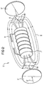
- the basic structure and the mode of operation of an optical Isolators 5 ' are shown in more detail in Fig. 2.
- the optical one Insulator 5 ' has a first polarizer 6', a Faraday rotator 7 'and a second polarizer 8'.
- the first Polarizer 6 ' generates a linearly polarized laser light beam 2 ', whose direction of polarization through the plane of polarization of the first polarizer 6 'and determined by the Vector 6a 'of the electric field strength E shown in FIG. 2 is specified.
- ⁇ 45 °
- the second polarizer 8 ' is set so that its The plane of polarization coincides with the vector 6b '. The laser light beam 2 'can thus unhindered the second polarizer 8' happen.
- the normals of the polarizers 6, 8 tilted relative to the beam axis of the laser light beam 2.
- the polarizers 6, 8 are thus used as beam splitters.
- a suitable decoupling ratio for the intensities of the first and second partial beams 10, 11, can by a corresponding Coating or anti-reflective coating of the polarizers 6, 8 can be set.
- the first partial beam 10 falls directly on a first detector 12 and is converted by the latter into a first electrical detector signal I 1 .
- the first detector signal I 1 corresponds to the intensity of the first partial beam 10 and is therefore proportional to the intensity of the laser light bundle 2.
- the second partial beam 11 runs through an optical filter 14.
- the optical filter 14 can be an edge filter (High-pass or low-pass filter) or by one on one of its Act band-pass filter operated filter edges.
- constructive can filter 14, for example, as a dielectric filter or be designed as an etalon.
- the filtered second partial beam 11 ′ that has passed through the filter 14 strikes a second detector 13.
- the second detector 13 generates a second electrical detector signal I 2 ( ⁇ ).
- the second electrical detector signal I 2 ( ⁇ ) is on the one hand proportional to the intensity of the laser light bundle 2 and on the other hand it is dependent on the laser light wavelength ⁇ due to the filter characteristic of the filter 14.
- the first and second partial beams 10, 11 'each with respect to the detector normal tilted are the first and second partial beams 10, 11 'each with respect to the detector normal tilted.
- the first detector 12 a tilt useful because its reflex is not due to the optical isolator 5 is eliminated.
- control electronics 15 which comprise a signal processing device 15a, a comparison device 15b and a control device 15c.
- the signal processing device 15a determines from the two detector signals I 1 and I 2 ( ⁇ ) an actual value signal IST ( ⁇ ) which is representative of the current laser light wavelength ⁇ and is independent of the intensity of the laser light beam 2, ie of the power of the semiconductor laser 1 ,
- a comparison device 15b connected downstream of the signal processing device 15a compares ACTUAL ( ⁇ ) with a desired value signal TARGET which specifies a desired desired wavelength ⁇ 0 .
- the comparison device 15b provides a signal ⁇ which is representative of the deviation between ACTUAL ( ⁇ ) and TARGET.
- the target wavelength ⁇ 0 can be predefined from outside.
- the deviation signal ⁇ is supplied to the control device 15c.
- the control device 15c then generates a Control signal C, the cooling element 16, for example a Peltier element that is fed.
- the cooling element 16 is in good thermal contact with the semiconductor laser 1.
- the regulation of the laser light wavelength ⁇ takes place via the Temperature dependence of the laser light emission in relation to ⁇ .
- the comparison device 15b and the control device 15c can for example in the form of a PI or a PID controller or can also be implemented as a digital controller.
- the wavelength-dependent transmission is one optical high-pass (filter curve 20) and an optical low-pass filter (Filter curve 21) shown, for example can be used as a filter 14.
- filter curve 20 an optical high-pass filter
- Finter curve 21 an optical low-pass filter
- the filter edges should be possible be steep. However, it should be borne in mind that a high Edge steepness reduced the capture area 22 of the scheme.
- the center wavelengths of the filters shown in Fig. 3a are identical.
- a filter is preferably used which can be operated in the vicinity of its center wavelength ⁇ M with respect to the desired wavelength ⁇ 0 (ie ⁇ M ⁇ ⁇ 0 ), since in this way an operating point with maximum steepness of the filter curve 20; 21 and a symmetrical capture area 22 can be obtained.
- the first detector signal I 1 is also wavelength-dependent, ie I 1 ( ⁇ ).
- the two filters 14, 17 preferably have opposite (complementary) filter curves with respect to the target wavelength ⁇ 0 .
- 3b shows suitable filter curves for the filter 14 and the filter 17.
- one of the filters 14; 17 a filter curve 23 and the other filter 17; 14 have a filter curve 24.
- Both bandpass filters are preferably operated in the region of their central wavelengths ⁇ M , which - as shown here - should expediently be identical.
- edge filters filters can be selected according to the filter curves 20 '(high-pass filter) and 21' (low-pass filter) which are shown in dash-dot lines and which correspond to the filter curves 20, 21 shown in FIG. 3a.
- the combination of an edge filter with a bandpass filter is also possible.
- the filter 14 and the optional filter 17 are preferably arranged pivotably. This enables a targeted adjustment of the center wavelength ⁇ M by tilting the respective filter 14, 17 with respect to the beam axis of the first or second partial beam 10, 11.
- the arrangement according to the invention can be used for a wide range of target wavelengths ⁇ 0 without changing the filter
- the tolerance requirements for the filters 14, 17 with regard to compliance with a center wavelength ⁇ M can be kept within a reasonable range, and a comparison of the center wavelength ⁇ M with the target wavelength ⁇ 0 and, if two filters 14, 17 are used, a comparison of the Center wavelengths of the two filters 14, 17 are carried out with each other.
- optical isolator 5 differs from that shown in FIG. 2 optical isolator 5 'in that for the Faraday twister 7 preferably a permanently magnetized material is used , whereby an external magnetic field B generating an outer Magnet (such as the solenoid 9 ') can be omitted.
- an external magnetic field B generating an outer Magnet such as the solenoid 9 '
- the first partial beam 10 is not on the first polarizer 6 from the Laser light bundle 2 can be coupled out, but can alternatively Way out of the second partial beam 11 Passing through the filter 14 or on a reflection layer be coupled out.
- the semiconductor laser 1 around an edge emitter there is also the possibility to use a laser beam as the first partial beam 11, which emits at an edge of the semiconductor laser 1 which is opposite the edge emitting the laser light beam 2.
- Fig. 4 shows a first practical embodiment of the in Fig. 1 illustrated embodiment.
- a laser chip 101 is arranged on a silicon carrier 100.
- a deflection prism 130 is also mounted, by means of which a emerging at a rear edge of the laser chip 101 additional laser light bundles can be deflected and coupled out can.
- the laser light bundle 102 emitted by the laser chip 101 passes through an aspherical lens 103, for example, which in a lens mount 132 is adjustably supported, and arrives into an optical isolator 105.
- the optical isolator 105 comprises a first polarizer in the manner already described 106, a Faraday rotator 107 and a second polarizer 108.
- the polarizers 106, 108 are for coupling out of first and second partial beams 110, 111 with respect to the Beam axis of the laser light bundle 102 is arranged inclined.
- the second sub-beam 111 passes through a pivotally arranged one optical filter 114.
- first and second optical detectors are designated, the as in Fig. 1 a first and a filtered second Partial beam 110 or 111 'received.
- the silicon carrier 100 is, for example, on an AlN base plate 133 attached and is in good thermal contact with this.
- the base plate 133, the lens frame 132 and the optical isolator 105 are common on a plate 134 assembled.
- the plate 134 can be made of silicon or AlN and is on a cooling surface of a Peltier element 116 below Training of a good heat transfer is appropriate.
- the temperature of the Peltier element 116 is described in that Regulated to keep the laser wavelength ⁇ constant.
- the structure shown is also a good one Constant temperature at the lens 103, at the optical isolator 105 and achieved on the filter 114.
- the tilt angle of the filter 114 is adjusted by pivoting the filter 114 with respect to the beam axis of the second partial beam 111.
- the filter 114 is then fixed in the adjustment position found by welding, soldering or gluing.
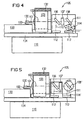
- FIG. 5 shows a second embodiment variant of the invention.
- the same parts as in Fig. 4 are given the same reference numerals characterized.
- the embodiment shown in Fig. 5 differs from that shown in FIG. 4 Variant essentially only in that instead of the adjustment of the tilt angle of the filter 114 here is the tilt angle of the second polarizer 108 'is adjustable for adjustment purposes is.
- the second polarizer 108 ' can be rotated on one mounted, lockable axle attached while the Filter 114 'is stationary. For example, it can be immediate fixed on the entrance window of the second detector 113 his.
- FIG. 6 shows a third embodiment variant of the invention, 4 and 5 with the same parts as in FIGS are identified by the same reference numerals.
- the in Fig. 6 shown embodiment variant differs from that in 4 and 5 variants shown essentially by that here a unit 115 consisting of the second polarizer 108 "and the filter 114" is tilt-adjustable, with a fixed relative position between the second polarizer 108 "and the filter 114" is provided.
- FIG. 7a shows a partial representation of a fourth in plan view Embodiment variant of the embodiment shown in Fig. 1.
- Variants here are the arrangement of the first and second polarizer 206 and 208, Faraday rotator 207, Filters 214 and first and second detectors 212 and 213 by 90 ° tilted.
- the laser light bundle 202 and the outcoupled Partial beams 210, 211, 211 'thus run in one plane parallel to a base plate 234 that the plate 134 in the Fig. 4 to 6 corresponds to and in a manner not shown carries the laser chip.
- the filter 214 is perpendicular about an axis pivotable to the base plate 234 while the second Polarizer 208 is fixed in position.
- the arrangement corresponds to that in Fig. 4 shown first embodiment.
- the adjustment options explained with reference to FIGS. 5 and 6 Swiveling second polarizer 208 or swiveling Unit of second polarizer 208 and filter 214) realized his.
- FIG. 7b shows a side view of the fourth embodiment variant from the direction of arrow X in Fig. 7a.
- the optical isolator 205 and filter 214 are on a common, first Intermediate carrier 231 attached while the detectors 212, 213 on an adjacently arranged detector carrier 232 are upset.
- the Deflection angle expediently deviates somewhat from 90 ° chosen so that that reflected by the detectors 212, 213 Light does not hit the laser chip.
- the fourth embodiment shown in FIGS. 7a, 7b the invention is particularly advantageous when a low Overall height (standing height above the base plate 234) of the laser arrangement is required.
- the signal processing device 15a, the comparison device 15b and the control device 15c outside or inside the module housing be arranged.
Description
Die Erfindung betrifft eine wellenlängenstabilisierte Laseranordnung
nach Anspruch 1.The invention relates to a wavelength-stabilized laser arrangement
according to
Es ist bereits bekannt, in optischen Übertragungssystemen auf einem Halbleiterlaser basierende Lasermodule zu verwenden, die zur Erzielung einer hohen Übertragungskapazität im Wellenlängenmultiplex-(WDM-) Verfahren betrieben werden. Um möglichst viele Kanäle übertragen zu können, müssen die Lasermodule hohen Anforderungen bezüglich ihrer Wellenlängenstabilität genügen.It is already known in optical transmission systems to use laser modules based on a semiconductor laser, to achieve a high transmission capacity in wavelength division multiplex (WDM) Process operated. Around The laser modules must be able to transmit as many channels as possible high requirements with regard to their wavelength stability suffice.
Ferner ist es bereits bekannt, derartige hochratige Lasermodule mit einem optischen Isolator auszurüsten. Der optische Isolator hat die Funktion, unerwünschte Rückwirkungen durch reflektiertes Laserlicht auf den Halbleiterlaser zu unterdrücken.Furthermore, such high-rate laser modules are already known to be equipped with an optical isolator. The optical one Isolator has the function of causing undesirable effects to suppress reflected laser light on the semiconductor laser.
Eine wellenlängenstabilisierte Laseranordnung ist in der nicht vorveröffentlichten deutschen Patentanmeldung DE 197 12 845.9 beschrieben. Zur Wellenlängenstabilisierung werden aus dem Laserlichtbündel zwei Teilstrahlen ausgekoppelt und von jeweiligen Detektoren detektiert. Zur Auskopplung der Teilstrahlen werden Strahlteiler oder Spiegel verwendet. Mindestens einer der Teilstrahlen durchläuft ein optisches Filter mit einer wellenlängenabhängigen Transmission, so daß das entsprechende detektierte Signal wellenlängenabhängig ist. Durch einen Vergleich des wellenlängenabhängigen Signals mit dem wellenlängenunabhängigen Signal des anderen Detektors wird die aktuelle Wellenlänge des Halbleiterlasers ermittelt und eine Abweichung zu einem vorgegebenen Sollwert bestimmt. Die Einstellung der Laserwellenlänge auf die Sollwellenlänge erfolgt dann über eine Temperaturregelung des Halbleiterlasers. A wavelength-stabilized laser arrangement is in the unpublished German patent application DE 197 12 845.9. The laser beam is used to stabilize the wavelength two partial beams decoupled and from each Detectors detected. To decouple the partial beams Beam splitter or mirror used. At least one the partial beams pass through an optical filter with a wavelength-dependent transmission, so that the corresponding detected signal is wavelength-dependent. Through a Comparison of the wavelength-dependent signal with the wavelength-independent one The signal from the other detector becomes the current one Wavelength of the semiconductor laser determined and a Deviation from a predetermined setpoint is determined. The setting the laser wavelength to the target wavelength then via a temperature control of the semiconductor laser.
Der Erfindung liegt die Aufgabe zugrunde, einen einfachen und kostengünstigen Aufbau einer für hohe Übertragungskapazitäten und insbesondere für Wellenlängenmultiplex geeigneten Laseranordnung mit einem Halbleiterlaser zu schaffen.The invention has for its object a simple and inexpensive construction of one for high transmission capacities and in particular a laser arrangement suitable for wavelength division multiplexing to create with a semiconductor laser.
Zur Lösung der Aufgabe sind die Merkmale des Anspruchs 1 vorgesehen.The features of
Die erfindungsgemäße Laseranordnung weist sowohl eine Wellenlängenstabilisierung als auch einen optischen Isolator auf und ist daher in besonderem Maße für die Übertragung hoher Datenraten im WDM-Betrieb geeignet. Erfindungsgemäß wird dabei zumindest einer der für die Wellenlängenstabilisierung benötigten Teilstrahlen über einen Polarisator des optischen Isolators ausgekoppelt. Der Polarisator erfüllt somit gleichzeitig zwei Funktionen, nämlich die eines Polarisators im optischen Isolator und die eines Strahlteilers in der Wellenlängenstabilisierungsschaltung. Dadurch wird ein Strahlteiler als zusätzliches Bauelement eingespart und es wird ein einfacher und kompakter Gesamtaufbau erzielt.The laser arrangement according to the invention has both wavelength stabilization as well as an optical isolator and is therefore particularly high for transmission Data rates suitable for WDM operation. According to the invention at least one of those for wavelength stabilization required partial beams via a polarizer of the optical Isolators decoupled. The polarizer thus fulfills two functions simultaneously, namely that of a polarizer in the optical isolator and that of a beam splitter in the wavelength stabilization circuit. This will make it a beam splitter saved as an additional component and it becomes a simple and compact overall structure achieved.
Vorzugsweise wird (zumindest) der zweite Polarisator als Strahlteiler eingesetzt und zur Auskopplung des zweiten Teilstrahls verwendet. In diesem Fall wirkt sich günstig aus, daß der optische Isolator Reflexe von dem Filter und von dem zweiten Detektor unterdrückt und somit verhindert, daß diese auf den Halbleiterlaser zurückwirken.The second polarizer is preferably (at least) as Beam splitter used and for coupling out the second partial beam used. In this case, that the optical isolator has reflections from the filter and from the suppresses the second detector and thus prevents this affect the semiconductor laser.
Ferner wird zweckmäßigerweise (auch) der erste Polarisator als Strahlteiler zur Auskopplung des ersten Teilstrahls eingesetzt. Auf diese Weise wird der Integrationsgrad und die Kompaktheit der erfindungsgemäßen Anordnung durch Einsparung eines weiteren Strahlteilers weiter gefördert.Furthermore, the first polarizer is expediently (also) used used as a beam splitter for coupling out the first partial beam. In this way the degree of integration and the Compactness of the arrangement according to the invention by saving another beam splitter.
Eine bevorzugte Ausgestaltung der Erfindung kennzeichnet sich dadurch, daß das Filter ein Kantenfilter oder ein Bandpaßfilter ist. Bei Verwendung eines Bandpaßfilters wird dieses an einer der Bandpaß-Filterkanten betrieben.A preferred embodiment of the invention is characterized in that the filter is an edge filter or a bandpass filter is. If a bandpass filter is used, this will turn on operated one of the bandpass filter edges.
Eine weitere bevorzugte Ausgestaltung der Erfindung kennzeichnet sich dadurch, daß ein weiteres Filter zur Filterung des zum ersten Detektor geführten ersten Teilstrahls eingesetzt wird. Dabei ist vorteilhaft, daß beide Filter mit linear polarisiertem Licht betrieben werden. Dies reduziert die an die Filter zu stellenden Anforderungen und ermöglicht den Einsatz kostengünstiger Filter.Another preferred embodiment of the invention features differs in that another filter for filtering of the first partial beam led to the first detector becomes. It is advantageous that both filters are linear polarized light can be operated. This reduces the requirements to be placed on the filters and enables the use of inexpensive filters.
Bei der Verwendung von zwei Filtern ist es bevorzugt, im Strahlengang des ersten Teilstrahls zwischen dem ersten Polarisator und dem weiteren Filter ein λ/2-Plättchen mit einer geeigneten Orientierung seiner optischen Achse anzuordnen. Das λ/2-Plättchen dient der Unterdrückung von an dem weiteren Filter auftretenden Reflexionen (sog. "Quasi-Isolator").When using two filters, it is preferred to use Beam path of the first partial beam between the first polarizer and the further filter a λ / 2 plate with a arrange appropriate orientation of its optical axis. The λ / 2 plate serves to suppress the other Reflections appearing in the filter (so-called "quasi-isolator").
Vorzugsweise weist das weitere Filter eine gegenüber der Filterkurve des Filters verschobene und bezüglich der Sollwel-Sollwellenlänge λ0 gegenläufige Filterkurve auf. Durch eine geeignete Auswertung der Detektorsignale kann in diesem Fall eine bei gleicher Filtersteilheit doppelt so hohe Wellenlängenempfindlichkeit wie bei der Verwendung nur eines Filters erzielt werden.The further filter preferably has a filter curve which is shifted with respect to the filter curve of the filter and runs counter to the target Wel target wavelength λ 0 . In this case, a suitable evaluation of the detector signals can achieve a wavelength sensitivity that is twice as high with the same filter steepness as when using only one filter.
Bei der Verwendung von zwei Filtern ist es ferner vorteilhaft, wenn die Filterkurve des Filters und die Filterkurve des weiteren Filters bei der Sollwellenlänge λ0 einen Schnittpunkt aufweisen. In diesem Fall kann die Wellenlänge des Halbleiterlasers mittels einer Nullpunktsregelung auf die Sollwellenlänge λ0 eingeregelt werden.When using two filters, it is also advantageous if the filter curve of the filter and the filter curve of the further filter have an intersection point at the desired wavelength λ 0 . In this case, the wavelength of the semiconductor laser can be adjusted to the target wavelength λ 0 by means of a zero point control.
Eine weitere bevorzugte Ausgestaltung der Erfindung kennzeichnet sich dadurch, daß das Filter und/oder das weitere Filter schwenkbar angeordnet sind. Die schwenkbare Anordnung eines Filters ermöglicht es, durch eine Verkippung des Filters relativ zu der Achse des einfallenden Teilstrahls eine Verstellung und Justage der Mittenwellenlänge λM des Filters vorzunehmen. Dadurch kann mit dem gleichen Filter ein ganzer Bereich von unterschiedlichen Sollwellenlängen abgedeckt werden, wodurch sich auch wechselnde Einsatzbedingungen ohne die Notwendigkeit eines Filteraustausches beherrschen lassen. Ferner ist eine einfache Justagemöglichkeit gegeben, die es erlaubt, die an das Filter zu stellenden Toleranzanforderungen in Hinblick auf die Einhaltung der Mittenwellenlänge λM zu reduzieren.Another preferred embodiment of the invention is characterized in that the filter and / or the further filter are arranged pivotably. The pivotable arrangement of a filter makes it possible to adjust and adjust the center wavelength λ M of the filter by tilting the filter relative to the axis of the incident partial beam. This means that the same filter can cover a whole range of different target wavelengths, which means that changing operating conditions can be mastered without the need to replace the filter. In addition, there is a simple adjustment possibility which makes it possible to reduce the tolerance requirements to be placed on the filter with regard to compliance with the center wavelength λ M.
Anstelle der Filter können auch der zweite Polarisator und/oder der erste Polarisator schwenkbar angeordnet sein, wodurch derselbe Effekt erzielt wird.The second polarizer can also be used instead of the filter and / or the first polarizer can be arranged pivotably, which gives the same effect.
Eine besonders kompakte Anordnung wird erreicht, wenn der zweite Polarisator und das Filter in zueinander lagefester Beziehung in einer gemeinsamen, schwenkbaren Einheit angeordnet sind.A particularly compact arrangement is achieved if the second polarizer and the filter in a more stable position to each other Relationship arranged in a common, pivotable unit are.
Die Einrichtung zum Drehen der Polarisationsebene ist vorzugsweise als ein Faradaydreher ausgebildet. In diesem Fall kennzeichnet sich eine bevorzugte Ausgestaltung der Erfindung dadurch, daß der Faradaydreher selbst permanent magnetisiert ist. Derartige Faradaydreher brauchen nicht mit einem äußeren Premanentmagneten ausgestattet werden, welcher die seitliche Auskopplung des oder der auszukoppelnden Teilstrahlen über den oder die Polarisatoren behindern oder erschweren kann.The device for rotating the plane of polarization is preferred trained as a Faraday turner. In this case features a preferred embodiment of the invention in that the Faraday rotator itself is permanently magnetized is. Such Faraday rotators do not need an external one Premanentmagnete be equipped, which the lateral Decoupling of the partial beam or beams to be coupled out obstruct or complicate about the polarizer (s) can.
Aufgrund ihrer Kompaktheit und Vielseitigkeit ist die erfindungsgemäße wellenlängenstabilisierte Laseranordnung insbesondere zum Aufbau von hochratigen Lasermodulen kleiner Baugrößen geeignet. Ein solches Lasermodul umfaßt neben der wellenlängenstabilisierten Laseranordnung ein hermetisch dichtes Modulgehäuse, das den Halbleiterlaser, den optischen Isolator und zumindest die optischen Detektoren und das optische Filter der Regeleinrichtung aufnimmt. Eine derartiges Lasermodul weist bei einer kompakten und kostengünstigen Aufbauweise den Vorteil einer internen Wellenlängenreferenz auf. Vorteilhaft ist ferner, daß bei einem solchen Modul die Anforderungen an das Filter weiter reduziert sind, da das Filter keinerlei Feuchtigkeit ausgesetzt ist und auch eine konstante Betriebstemperatur des Filters durch Ankopplung an eine den Halbleiterlaser kühlende Kühleinrichtung in einfacher Weise herbeigeführt werden kann.Because of its compactness and versatility, the invention is Wavelength-stabilized laser arrangement in particular for the construction of high-rate laser modules of small sizes suitable. Such a laser module includes in addition to the wavelength-stabilized laser arrangement a hermetic dense module housing that the semiconductor laser, the optical Isolator and at least the optical detectors and the optical Filters the control device. Such one Laser module has a compact and inexpensive construction the advantage of an internal wavelength reference. It is also advantageous that the requirements of such a module to the filter are further reduced because the filter is not exposed to any moisture and also a constant Operating temperature of the filter by coupling to a the cooling device cooling the semiconductor laser in simple Way can be brought about.
Weitere vorteilhafte Ausgestaltungen der Erfindung sind in den Unteransprüchen angegeben.Further advantageous embodiments of the invention are in specified in the subclaims.
Die Erfindung wird nachfolgend in beispielhafter Weise anhand eines Ausführungsbeispiels und Varianten desselben unter Bezugnahme auf die Zeichnung beschrieben; in dieser zeigt:
- Fig. 1
- eine schematische Darstellung eines Ausführungsbeispiels der Erfindung;
- Fig. 2
- eine Darstellung zur Erläuterung des Aufbaus und der Wirkungsweise eines optischen Isolators;
- Fig. 3a
- ein Diagramm, das die Wellenlängenabhängigkeit der Transmission eines optischen Hochpaßfilters und eines optischen Tiefpaßfilters zeigt;
- Fig. 3b
- ein Diagramm, das die Wellenlängenabhängigkeit der Transmission zweier optischer Bandpaßfilter zeigt;
- Fig. 3c
- ein Diagramm, das bzgl. der Fig. 3a die funktionale Abhängigkeit des Istwertes (I1-I2)/(I1+I2) von der Wellenlänge für den Fall zeigt, daß die beiden Filter ein Hochpaß- und ein Tiefpaßfilter sind, deren Transmissionskurven sich bei der Mittelwertlänge λM schneiden;
- Fig. 4
- eine schematische Seitenansicht einer ersten Variante des in Fig. 1 dargestellten Ausführungsbeispiels;
- Fig. 5
- eine schematische Seitenansicht einer zweiten Variante des in Fig. 1 dargestellten Ausführungsbeispiels;
- Fig. 6
- eine schematische Seitenansicht einer dritten Variante des in Fig. 1 dargestellten Ausführungsbeispiels;
- Fig. 7a
- eine schematische Darstellung einer vierten Ausführungsvariante des in Fig. 1 dargestellten Ausführungsbeispiels in Draufsicht; und
- Fig. 7b
- eine Seitenansicht der in Fig. 7a dargestellten vierten Ausführungsvariante aus Richtung des Pfeils X in der Fig. 7a.
- Fig. 1
- a schematic representation of an embodiment of the invention;
- Fig. 2
- a representation for explaining the structure and operation of an optical isolator;
- Fig. 3a
- a diagram showing the wavelength dependency of the transmission of an optical high-pass filter and an optical low-pass filter;
- Fig. 3b
- a diagram showing the wavelength dependency of the transmission of two optical bandpass filters;
- Fig. 3c
- 3 a shows the functional dependency of the actual value (I 1 -I 2 ) / (I 1 + I 2 ) on the wavelength in relation to FIG. 3a in the event that the two filters are a high-pass and a low-pass filter, whose transmission curves intersect at the mean length λ M ;
- Fig. 4
- is a schematic side view of a first variant of the embodiment shown in Fig. 1;
- Fig. 5
- is a schematic side view of a second variant of the embodiment shown in Fig. 1;
- Fig. 6
- is a schematic side view of a third variant of the embodiment shown in Fig. 1;
- Fig. 7a
- a schematic representation of a fourth embodiment of the embodiment shown in Figure 1 in plan view; and
- Fig. 7b
- a side view of the fourth embodiment shown in Fig. 7a from the direction of arrow X in Fig. 7a.
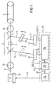
Nach Fig. 1 weist ein Ausführungsbeispiel der Erfindung einen
Halbleiterlaser 1 auf, der ein Laserlichtbündel 2 emittiert.
Das Laserlichtbündel 2 wird von einer Optik, die aus einer
oder mehreren Linsen bestehen kann, kollimiert oder auf eine
Eintrittsfläche einer Glasfaser 4 fokussiert. Im letztgenannten
Fall kann die Optik wie hier dargestellt beispielsweise
aus zwei Linsen (oder Linsengruppen) 3a, 3b bestehen,
wobei die erste Linse 3a ein näherungsweise kollimiertes Laserlichtbündel
erzeugt, das von der zweiten Linse 3b fokussiert
wird.1 shows an embodiment of the
Im Strahlengang hinter der Linse 3a befindet sich ein optischer
Isolator 5, der aus einem ersten Polarisator 6, einem
Faradaydreher 7 und einem zweiten Polarisator 8 aufgebaut
ist.There is an optical one in the beam path behind the
Ein optischer Isolator ist als solcher in der Technik bekannt
und dient dazu, unerwünschte Rückwirkungen von reflektiertem
Laserlicht auf den Halbleiterlaser 1 zu unterdrücken. Der
prinzipielle Aufbau und die Wirkungsweise eines optischen
Isolators 5' sind in Fig. 2 näher dargestellt. Der optische
Isolator 5' weist einen ersten Polarisator 6', einen Faradaydreher
7' und einen zweiten Polarisator 8' auf. Der erste
Polarisator 6' erzeugt ein linear polarisiertes Laserlichtbündel
2', dessen Polarisationsrichtung durch die Polarisationsebene
des ersten Polarisators 6' bestimmt und durch den
in Fig. 2 gezeigten Vektor 6a' der elektrischen Feldstärke E
angegeben ist. Beim Durchlaufen des Faradaydrehers 7' wird
der Vektor 6a' der elektrischen Feldstärke um einen vorgegebenen
Drehwinkel α (bspw. α = 45°) gedreht. Für diese auf
dem sog. Faradayeffekt beruhende Drehung der Polarisationsebene
bedarf es eines Magnetfeldes B, das beispielsweise von
außen mittels einer Magnetspule 9' oder eines Permanentmagneten
an den Faradaydreher 7' angelegt wird. Das Bezugszeichen
6b' kennzeichnet den Vektor der elektrischen Feldstärke
des Laserlichtbündels 2' nach Durchlaufen des Faradaydrehers
7'. Der zweite Polarisator 8' ist so eingestellt, daß seine
Polarisationsebene mit dem Vektor 6b' zusammenfällt. Das Laserlichtbündel
2' kann somit den zweiten Polarisator 8' ungehindert
passieren.As such, an optical isolator is known in the art
and serves to avoid unwanted repercussions from reflected
Suppress laser light on the
Zurückkehrende Lichtreflexe "sehen" im Faradaydreher 7' ein
entgegengesetzt gerichtetes Magnetfeld B. Ihre durch den
zweiten Polarisator 8' vorgegebene Polarisationsrichtung wird
deshalb bzgl. der Strahlrichtung mit entgegengesetztem Drehsinn
verdreht. Die sich ergebende Polarisationsrichtung hinter
dem Faradaydreher 7' ist senkrecht zu dem Vektor 6a' orientiert.
Folglich kann der Reflex den Polarisator 6' nicht
passieren, wodurch eine unerwünschte Rückwirkung auf den
Halbleiterlaser 1 ausgeschlossen ist.Returning light reflections "see" in the Faraday twister 7 '
oppositely directed magnetic field B. Your through the
second polarizer 8 'predetermined polarization direction
therefore with respect to the beam direction with opposite direction of rotation
twisted. The resulting direction of polarization behind
the Faraday rotator 7 'is oriented perpendicular to the
Bei einer erfindungsgemäßen Anordnung wird zumindest einer
der Polarisatoren 6, 8 - oder wie in Fig. 1 dargestellt vorzugsweise
beide Polarisatoren 6, 8 - zur Auskopplung von ersten
und zweiten Teilstrahlen 10, 11 aus dem Laserlichtbündel
2 genutzt. Hierzu werden die Normalen der Polarisatoren 6, 8
gegenüber der Strahlachse des Laserlichtbündels 2 verkippt. In an arrangement according to the invention, at least one
the
Die Polarisatoren 6, 8 werden somit als Strahlteiler genutzt.
Ein geeignetes Auskoppelverhältnis für die Intensitäten der
ersten und zweiten Teilstrahlen 10, 11, kann durch eine entsprechende
Ver- oder Entspiegelung der Polarisatoren 6, 8
eingestellt werden.The
Der erste Teilstrahl 10 fällt direkt auf einen ersten Detektor
12 und wird von diesem in ein erstes elektrisches Detektorsignal
I1 umgewandelt. Das erste Detektorsignal I1 entspricht
der Intensität des ersten Teilstrahl 10 und ist somit
proportional zu der Intensität des Laserlichtbündels 2.The first
Der zweite Teilstrahl 11 läuft durch ein optisches Filter 14.
Bei dem optischen Filter 14 kann es sich um ein Kantenfilter
(Hochpaß- oder Tiefpaßfilter) oder um ein an einer seiner
Filterkanten betriebenes Bandpaßfilter handeln. Konstruktiv
kann das Filter 14 beispielsweise als dielektrisches Filter
oder als Etalon ausgeführt sein.The second
Der durch das Filter 14 hindurchgetretene, gefilterte zweite
Teilstrahl 11' trifft auf einen zweiten Detektor 13. Der
zweite Detektor 13 erzeugt ein zweites elektrisches Detektorsignal
I2(λ). Das zweite elektrische Detektorsignal I2(λ)
ist einerseits proportional zu der Intensität des Laserlichtbündels
2 und es ist andererseits aufgrund der Filtercharakteristik
des Filters 14 von der Laserlicht-Wellenlänge λ abhängig.The filtered second
Um Rückwirkungen auf den Halbleiterlaser durch Reflexionen an
den Detektoren 12 und 13 zu vermeiden, sind die ersten und
zweiten Teilstrahlen 10, 11' jeweils gegenüber den Detektornormalen
verkippt. Insbesondere beim ersten Detektor 12 ist
eine Verkippung zweckmäßig, da dessen Reflex nicht durch den
optischen Isolator 5 eliminiert wird.To repercussions on the semiconductor laser through reflections
to avoid
Die beiden Detektorsignale I1 und I2(λ) werden einer Regelelektronik
15 zugeführt, die eine Signalverarbeitungseinrichtung
15a, eine Vergleichseinrichtung 15b und eine Ansteuereinrichtung
15c umfaßt.The two detector signals I 1 and I 2 (λ) are fed to control
Die Signalverarbeitungseinrichtung 15a ermittelt aus den beiden
Detektorsignalen I1 und I2(λ) ein Istwertsignal IST(λ),
welches für die aktuelle Laserlicht-Wellenlänge λ repräsentativ
und unabhängig von der Intensität des Laserlichtbündels
2, d.h. von der Leistung des Halbleiterlasers 1, ist.The
Als Istwertsignal IST(λ) kann beispielsweise der Quotient aus dem zweiten Detektorsignal I2(λ) und dem ersten Detektorsignal I1 verwendet werden, d.h. IST(λ) = I2(λ)/I1, da sich in diesem Fall die Leistungsabhängigkeit dieser beiden Signale gerade herauskürzt.The quotient of the second detector signal I 2 (λ) and the first detector signal I 1 can be used, for example, as the actual value signal IST (λ), ie IST (λ) = I 2 (λ) / I 1 , since in this case the power dependency of these two signals just cuts out.
Eine der Signalverarbeitungseinrichtung 15a nachgeschaltete
Vergleichseinrichtung 15b vergleicht IST(λ) mit einem Sollwertsignal
SOLL, das eine gewünschte Sollwellenlänge λ0 vorgibt.
Die Vergleichseinrichtung 15b stellt ein Signal Δ bereit,
das für die Abweichung zwischen IST(λ) und SOLL repräsentativ
ist. Die Sollwellenlänge λ0 kann dabei von außen
veränderlich vorgegeben werden.A
Das Abweichungssignal Δ wird der Ansteuereinrichtung 15c zugeführt.
Die Ansteuereinrichtung 15c erzeugt daraufhin ein
Steuersignal C, das einem Kühlelement 16, beispielsweise einem
Peltier-Element, zugeleitet wird. Das Kühlelement 16
steht mit dem Halbleiterlaser 1 in gutem thermischen Kontakt.
Die Regelung der Laserlicht-Wellenlänge λ erfolgt über die
Temperaturabhängigkeit der Laserlichtemission in bezug auf λ.The deviation signal Δ is supplied to the control device 15c.
The control device 15c then generates a
Control signal C, the
Die Vergleichseinrichtung 15b und die Ansteuereinrichtung 15c
können beispielsweise in Form eines PI- oder eines PID-Reglers
oder auch als digitaler Regler realisiert sein.The
In Fig. 3a ist die wellenlängenabhängige Transmission eines
optischen Hochpaß- (Filterkurve 20) und eines optischen Tiefpaßfilters
(Filterkurve 21) dargestellt, wie sie beispielsweise
als Filter 14 zur Anwendung kommen können. Für eine
hohe spektrale Auflösung sollten die Filterflanken möglichst
steil sein. Allerdings ist zu berücksichtigen, daß eine hohe
Flankensteilheit den Fangbereich 22 der Regelung verkleinert.3a, the wavelength-dependent transmission is one
optical high-pass (filter curve 20) and an optical low-pass filter
(Filter curve 21) shown, for example
can be used as a filter 14. For one
high spectral resolution, the filter edges should be possible
be steep. However, it should be borne in mind that a high
Edge steepness reduced the
Die Mittenwellenlänge λM eines Filters ist durch die Bedingung
"Transmission(λM) = 50%" bestimmt. Die Mittenwellenlängen
der in Fig. 3a dargestellten Filter sind identisch. Vorzugsweise
wird ein Filter verwendet, das bezüglich der gewünschten
Sollwellenlänge λ0 in der Nähe seiner Mittenwellenlänge
λM betrieben werden kann (d.h. λM ≈ λ0), da auf diese
Weise ein Arbeitspunkt bei maximaler Steilheit der Filterkurve
20; 21 sowie ein symmetrischer Fangbereich 22 erhalten
werden.The center wavelength λ M of a filter is determined by the condition "transmission (λ M ) = 50%". The center wavelengths of the filters shown in Fig. 3a are identical. A filter is preferably used which can be operated in the vicinity of its center wavelength λ M with respect to the desired wavelength λ 0 (ie λ M ≈ λ 0 ), since in this way an operating point with maximum steepness of the
Es ist auch möglich, zur Wellenlängenregelung ein weiteres
wellenlängenselektives Filter 17 zu verwenden. Ein solches
ist in Fig. 1 strichpunktiert im Strahlengang des ersten
Teilstrahls 10 eingezeichnet. In diesem Fall ist auch das
erste Detektorsignal I1 wellenlängenabhängig, d.h. I1(λ).It is also possible to use a further wavelength-
Die beiden Filter 14, 17 weisen vorzugsweise möglichst gegenläufige
(komplementäre) Filterkurven bzgl. der Sollwellenlänge
λ0 auf. In Fig. 3b sind geeignete Filterkurven für das
Filter 14 und das Filter 17 dargestellt. Bei Verwendung von
Bandpaßfiltern kann eines der Filter 14; 17 eine Filterkurve
23 und das andere Filter 17; 14 eine Filterkurve 24 aufweisen.
Beide Bandpaßfilter werden vorzugsweise im Bereich ihrer
Mittelwellenlängen λM betrieben, die - wie hier dargestellt
- zweckmäßigerweise identisch sein sollten. Bei Verwendung
von Kantenfiltern können Filter gemäß den strichpunktiert
eingezeichneten Filterkurven 20' (Hochpaßfilter) und
21' (Tiefpaßfilter) gewählt werden, die den in Fig. 3a dargestellten
Filterkurven 20, 21 entsprechen. Die Kombination
eines Kantenfilters mit einem Bandpaßfilter ist ebenfalls
möglich. The two
Bei Verwendung von zwei Filtern 14, 17 kann das von der Laserleistung
unabhängige Istwertsignal IST(λ) beispielsweise
über die Beziehung
Das Filter 14 sowie das optionale Filter 17 sind vorzugsweise
schwenkbar angeordnet. Dies ermöglicht eine gezielte Einstellung
der Mittenwellenlänge λM durch Verkippung des jeweiligen
Filters 14, 17 gegenüber der Strahlachse des ersten
bzw. zweiten Teilstrahls 10, 11. Dadurch kann die erfindungsgemäße
Anordnung ohne einen Filterwechsel für einen
breiten Bereich von Sollwellenlängen λ0 eingesetzt werden, es
können die Toleranzanforderungen an die Filter 14, 17 bzgl.
der Einhaltung einer Mittenwellenlänge λM in einem vernünftigen
Rahmen gehalten werden, und es kann ein Abgleich der Mittenwellenlänge
λM auf die Sollwellenlänge λ0 sowie bei Verwendung
von zwei Filtern 14, 17 ein Abgleich der Mittenwellenlängen
der beiden Filter 14, 17 untereinander durchgeführt
werden.The filter 14 and the
Neben der Auskopplung der Teilstrahlen 10, 11 unterscheidet
sich der optische Isolator 5 von dem in Fig. 2 dargestellten
optischen Isolator 5' dadurch, daß für den Faradaydreher 7
vorzugsweise ein permanent magnetisiertes Material eingesetzt
wird, wodurch ein ein externes Magnetfeld B erzeugender äußerer
Magnet (etwa die Magnetspule 9') entfallen kann. Dadurch
wird die erfindungsgemäße seitliche Strahlauskopplung an den
Polarisatoren 6, 8 wesentlich erleichtert.In addition to decoupling the
Es sind eine Vielzahl von Abwandlungen des in Fig. 1 dargestellten
Ausführungsbeispiels möglich. Beispielsweise muß
der erste Teilstrahl 10 nicht am ersten Polarisator 6 aus dem
Laserlichtbündel 2 ausgekoppelt werden, sondern kann in alternativer
Weise auch aus dem zweiten Teilstrahl 11 vor
Durchlaufen des Filters 14 oder an einer Reflexionsschicht
desselben ausgekoppelt werden. Handelt es sich bei dem Halbleiterlaser
1 um einen Kantenemitter, besteht ferner die Möglichkeit,
als ersten Teilstrahl 11 einen Laserstrahl zu nutzen,
der an einer Kante des Halbleiterlasers 1 emittiert
wird, die der das Laserlichtbündel 2 emittierenden Kante gegenüberliegt.There are a variety of modifications to that shown in FIG. 1
Embodiment possible. For example, must
the first
Fig. 4 zeigt eine erste praktische Ausführungsvariante des in Fig. 1 dargestellten Ausführungsbeispiels.Fig. 4 shows a first practical embodiment of the in Fig. 1 illustrated embodiment.
Ein Laserchip 101 ist auf einem Siliziumträger 100 angeordnet.
Auf dem auch als Silizium-Submount bezeichneten Träger
100 ist ferner ein Umlenkprisma 130 montiert, mittels dem ein
an einer rückwärtigen Kante des Laserchips 101 austretendes
weiteres Laserlichtbündel umgelenkt und ausgekoppelt werden
kann.A
Das von dem Laserchip 101 emittierte Laserlichtbündel 102
durchläuft eine beispielsweise asphärische Linse 103, die in
einer Linsenfassung 132 justierbar gehaltert ist, und gelangt
in einen optischen Isolator 105. Der optische Isolator 105
umfaßt in der bereits beschriebenen Weise einen ersten Polarisator
106, einen Faradaydreher 107 und einen zweiten Polarisator
108. Die Polarisatoren 106, 108 sind zur Auskopplung
von ersten und zweiten Teilstrahlen 110, 111 gegenüber der
Strahlachse des Laserlichtbündels 102 geneigt angeordnet.
Der zweite Teilstrahl 111 durchläuft ein schwenkbar angeordnetes
optisches Filter 114. Mit den Bezugszeichen 112 und
113 sind erste und zweite optische Detektoren bezeichnet, die
wie in Fig. 1 einen ersten bzw. einen gefilterten zweiten
Teilstrahl 110 bzw. 111' empfangen.The
Der Siliziumträger 100 ist beispielsweise auf einer AlN-Grundplatte
133 angebracht und steht mit dieser in gutem Wärmekontakt.
Die Grundplatte 133, die Linsenfassung 132 und
der optische Isolator 105 sind gemeinsam auf einer Platte 134
montiert. Die Platte 134 kann aus Silizium oder AlN bestehen
und ist auf einer Kühlfläche eines Peltier-Elements 116 unter
Ausbildung eines guten Wärmeübergangs angebracht. Die Temperatur
des Peltier-Elements 116 wird in der bereits beschriebenen
Weise zur Konstanthaltung der Laserwellenlänge λ geregelt.
Durch den dargestellten Aufbau wird auch eine gute
Temperaturkonstanz an der Linse 103, an dem optischen Isolator
105 und an dem Filter 114 erzielt.The
Zur Justage der Mittenwellenlänge λM wird durch Verschwenken
des Filters 114 der Kippwinkel desselben bzgl. der Strahlachse
des zweiten Teilstrahls 111 verstellt. Das Filter 114
wird dann durch Schweißen, Löten oder Kleben in der gefundenen
Justagestellung fixiert.To adjust the center wavelength λ M , the tilt angle of the
Fig. 5 zeigt eine zweite Ausführungsvariante der Erfindung.
Gleiche Teile wie in der Fig. 4 sind mit den gleichen Bezugszeichen
gekennzeichnet. Die in Fig. 5 gezeigte Ausführungsvariante
unterscheidet sich von der in Fig. 4 dargestellten
Variante im wesentlichen nur dadurch, daß anstelle der Verstellung
des Kippwinkels des Filters 114 hier der Kippwinkel
des zweiten Polarisators 108' zu Justagezwecken verstellbar
ist. Hierfür ist der zweite Polarisator 108' an einer drehbar
gelagerten, arretierbaren Achse angebracht, während das
Filter 114' ortsfest ist. Es kann beispielsweise unmittelbar
auf dem Eintrittsfenster des zweiten Detektors 113 fixiert
sein.5 shows a second embodiment variant of the invention.
The same parts as in Fig. 4 are given the same reference numerals
characterized. The embodiment shown in Fig. 5
differs from that shown in FIG. 4
Variant essentially only in that instead of the adjustment
of the tilt angle of the
Fig. 6 zeigt eine dritte Ausführungsvariante der Erfindung,
wobei auch hier gleiche Teile wie in den Fig. 4 und 5 mit den
gleichen Bezugszeichen gekennzeichnet sind. Die in Fig. 6
gezeigte Ausführungsvariante unterscheidet sich von den in
Fig. 4 und 5 dargestellten Varianten im wesentlichen dadurch,
daß hier eine Einheit 115 bestehend aus dem zweiten Polarisator
108" und dem Filter 114'' kippverstellbar angeordnet ist,
wobei eine feste Relativlage zwischen dem zweiten Polarisator
108" und dem Filter 114" vorgesehen ist.6 shows a third embodiment variant of the invention,
4 and 5 with the same parts as in FIGS
are identified by the same reference numerals. The in Fig. 6
shown embodiment variant differs from that in
4 and 5 variants shown essentially by
that here a
Fig. 7a zeigt in Draufsicht eine Teildarstellung einer vierten
Ausführungsvariante des in Fig. 1 dargestellten Ausführungsbeispiels.
Gegenüber den in den Fig. 4 bis 6 dargestellten
Ausführungsvarianten ist hier die Anordnung aus erstem
und zweitem Polarisator 206 und 208, Faradaydreher 207,
Filter 214 und erstem und zweitem Detektor 212 und 213 um 90°
gekippt. Das Laserlichtbündel 202 und die ausgekoppelten
Teilstrahlen 210, 211, 211' verlaufen somit in einer Ebene
parallel zu einer Basisplatte 234, die der Platte 134 in den
Fig. 4 bis 6 entspricht und die in nicht dargestellter Weise
den Laserchip trägt. Das Filter 214 ist um eine Achse senkrecht
zu der Basisplatte 234 verschwenkbar, während der zweite
Polarisator 208 lagefest ausgeführt ist. In bezug auf die
Justageverhältnisse entspricht die Anordnung somit der in
Fig. 4 gezeigten ersten Ausführungsvariante. In analoger
Weise können bei der gekippten vierten Ausführungsvariante
auch die anhand der Fig. 5 und 6 erläuterten Justagemöglichkeiten
(schwenkbarer zweiter Polarisator 208 bzw. schwenkbare
Einheit aus zweitem Polarisator 208 und Filter 214) realisiert
sein.7a shows a partial representation of a fourth in plan view
Embodiment variant of the embodiment shown in Fig. 1.
Compared to that shown in FIGS. 4 to 6
Variants here are the arrangement of the first
and
Fig. 7b zeigt eine Seitenansicht der vierten Ausführungsvariante
aus Richtung des Pfeils X in Fig. 7a. Der optische Isolator
205 und das Filter 214 sind auf einem gemeinsamen, ersten
Zwischenträger 231 angebracht, während die Detektoren
212, 213 auf einem benachbart angeordneten Detektorträger 232
aufgebracht sind. Oberhalb des Detektorträgers 232 befindet
sich ein Umlenkprisma 230, das die beiden Teilstrahlen 210
und 211' auf die jeweiligen Detektoren 212, 213 umlenkt. Der
Umlenkwinkel wird zweckmäßigerweise etwas von 90° abweichend
gewählt, damit das von den Detektoren 212, 213 reflektierte
Licht nicht auf den Laserchip zurücktrifft.7b shows a side view of the fourth embodiment variant
from the direction of arrow X in Fig. 7a. The
Die in den Fig. 7a, 7b gezeigte vierte Ausführungsvariante der Erfindung ist insbesondere dann günstig, wenn eine niedrige Bauhöhe (Standhöhe über der Grundplatte 234) der Laseranordnung gefordert ist.The fourth embodiment shown in FIGS. 7a, 7b the invention is particularly advantageous when a low Overall height (standing height above the base plate 234) of the laser arrangement is required.
Aufgrund ihres geringen Platzbedarfs lassen sich die in den
Fig. 4 bis 7c gezeigten Aufbauten in einfacher Weise in einem
nicht dargestellten hermetisch dichten Modulgehäuse unterbringen.
Dabei können die Signalverarbeitungseinrichtung
15a, die Vergleichseinrichtung 15b und die Ansteuereinrichtung
15c außerhalb oder aber auch innerhalb des Modulgehäuses
angeordnet sein. Due to their small footprint, they can be used in the
4 to 7c structures shown in a simple manner in one
Place the hermetically sealed module housing, not shown.
The
- 11
- HalbleiterlaserSemiconductor laser
- 2, 2'2, 2 '
- LaserlichtbündelLaser beam
- 3a3a
- erste Linsefirst lens
- 3b3b
- zweite Linsesecond lens
- 44
- Glasfaserglass fiber
- 5, 5'5, 5 '
- optischer Isolatoroptical isolator
- 6, 6'6, 6 '
- erster Polarisatorfirst polarizer
- 6a'6a '
- Vektor der el. FeldstärkeVector of el. Field strength
- 6b'6b '
- Vektor der el. FeldstärkeVector of el. Field strength
- 7, 7'7, 7 '
- FaradaydreherFaraday rotator
- 8, 8'8, 8 '
- zweiter Polarisatorsecond polarizer
- 9'9 '
- Magnetspulesolenoid
- 1010
- erster Teilstrahlfirst partial beam
- 1111
- zweiter Teilstrahlsecond sub-beam
- 11'11 '
- gefilterter zweiter Teilstrahlfiltered second sub-beam
- 1212
- erster Detektorfirst detector
- 1313
- zweiter Detektorsecond detector
- 1414
- optisches Filteroptical filter
- 1515
- Regelelektronikcontrol electronics
- 15a15a
- SignalverarbeitungseinrichtungSignal processing device
- 15b15b
- Vergleichseinrichtungcomparator
- 15c15c
- Ansteuereinrichtungdriving
- 1616
- Kühlelementcooling element
- 1717
- weiteres optisches Filteranother optical filter
- 20, 20'20, 20 '
- Filterkurve (Hochpaßfilter)Filter curve (high pass filter)
- 21, 21'21, 21 '
- Filterkurve (Tiefpaßfilter)Filter curve (low pass filter)
- 2222
- Fangbereichcapture area
- 2323
- Filterkurve (Bandpaßfilter)Filter curve (bandpass filter)
- 2424
- Filterkurve (Bandpaßfilter)Filter curve (bandpass filter)
- 2525
- Fangbereichcapture area
- 100100
- Siliziumträgersilicon carrier
- 101101
- Laserchip laser chip
- 102102
- LaserlichtbündelLaser beam
- 103103
- Linselens
- 105105
- optischer Isolatoroptical isolator
- 106106
- erster Polarisatorfirst polarizer
- 107107
- FaradaydreherFaraday rotator
- 108, 108', 108"108, 108 ', 108 "
- zweiter Polarisatorsecond polarizer
- 110110
- erster Teilstrahlfirst partial beam
- 111111
- zweiter Teilstrahlsecond sub-beam
- 111'111 '
- gefilterter zweiter Teilstrahlfiltered second sub-beam
- 112112
- erster Detektorfirst detector
- 113113
- zweiter Detektorsecond detector
- 114, 114', 114"114, 114 ', 114 "
- optisches Filteroptical filter
- 115115
- Einheitunit
- 116116
- Peltier-ElementPeltier element
- 130130
- Umlenkprismadeflecting prism
- 132132
- Linsenfassunglens mount
- 133133
- Grundplattebaseplate
- 134134
- Platteplate
- 202202
- LaserlichtbündelLaser beam
- 205205
- optischer Isolatoroptical isolator
- 206206
- erster Polarisatorfirst polarizer
- 207207
- FaradaydreherFaraday rotator
- 208208
- zweiter Polarisatorsecond polarizer
- 210210
- erster Teilstrahlfirst partial beam
- 211211
- zweiter Teilstrahlsecond sub-beam
- 211'211 '
- gefilterter zweiter Teilstrahlfiltered second sub-beam
- 212212
- erster Detektorfirst detector
- 213213
- zweiter Detektorsecond detector
- 214214
- optisches Filteroptical filter
- 230230
- Umlenkprismadeflecting prism
- 231231
- Zwischenträgersubcarrier
- 232232
- Detektorträger detector support
- 234234
- Basisplattebaseplate
- αα
- Drehwinkel der PolarisationsebeneAngle of rotation of the plane of polarization
- BB
- Magnetfeldmagnetic field
- CC
- Steuersignalcontrol signal
- ΔΔ
- Signalsignal
- I1 I 1
- erstes Detektorsignalfirst detector signal
- I2 I 2
- zweites Detektorsignalsecond detector signal
- XX
- Pfeilarrow
Claims (21)
- Wavelength-stabilized laser arrangement havinga semiconductor laser (1; 101) anda regulating device comprisinga first optical detector (12; 112; 212), to which is fed a first partial beam (10) coupled out by the semiconductor laser (1, 101),an optical filter (14; 114, 114', 114''; 214),a second optical detector (13; 113; 213), to which is fed a second partial beam (11'; 111'; 211') coupled out by the semiconductor laser (1, 101) and filtered by the optical filter (14; 114, 114', 114''; 214),a signal processing device (15a), to which an output signal (I1) of the first optical detector (12, 112; 212) and an output signal (I2) of the second optical detector (13; 113; 213) are fed and which determines from the two output signals (I1, I2) an actual value signal (ACTUAL(λ)), which is representative of the instantaneous laser wavelength λ and is independent of the laser power,a comparison device (15b), which compares the actual value signal (ACTUAL(λ)) with a predetermined desired value signal (DESIRED), which specifies a desired wavelength λ0, anda drive device (15c), which generates a control signal (C) that sets an operating parameter of the semiconductor laser, said parameter influencing the wavelength λ to be stabilized, in such a way that the actual value signal (ACTUAL(λ)) essentially corresponds to the desired value signal (DESIRED),an optical isolator (5; 105; 205) arranged in the beam path (2, 102, 202) of the semiconductor laser and havinga first polarizer (6; 106; 206),a device (7; 107; 207) for rotating the plane of polarization of the light, said device being connected downstream of the first polarizer (6; 106; 206), anda second polarizer (8; 108; 208), which is connected downstream of the device (7; 107; 207) for rotating the plane of polarization of the light,at least one of the two polarizers (6; 106; 206; 8; 108; 208) being used as a beam splitter for coupling out the first or second partial beam (10; 110; 210; 11; 111; 211).
- Wavelength-stabilized laser arrangement according to Claim 1, characterized in that the second polarizer (8; 108; 208) is used as a beam splitter for coupling out the second partial beam (11; 111; 211).
- Wavelength-stabilized laser arrangement according to Claim 1 or 2, characterized in that the first polarizer (6; 106; 206) is used as a beam splitter for coupling out the first partial beam (10; 110; 210).
- Wavelength-stabilized laser arrangement according to one of the preceding claims, characterized in that the polarizer or polarizers (6; 106; 206; 8; 108; 208) used as beam splitters are partly reflective polarization filters arranged at an inclination relative to an incident laser light pencil (2, 102, 202).
- Wavelength-stabilized laser arrangement according to one of the preceding claims, characterized in that the optical filter (14; 114, 114', 114''; 214) is a cut-off filter or a bandpass filter.
- Wavelength-stabilized laser arrangement according to one of Claims 2 to 5, characterized in that there is a further filter (17) present for filtering the first partial beam (10; 110; 210) guided to the first detector (12; 112; 212).
- Wavelength-stabilized laser arrangement according to Claim 6, characterized in that a λ/2 plate is arranged in the beam path of the first partial beam (10; 110; 210) between the first polarizer (6; 106; 206) and the further filter (17).
- Wavelength-stabilized laser arrangement according to either of Claims 6 and 7, characterized in that the further filter (17) is a cut-off filter or a bandpass filter.
- Wavelength-stabilized laser arrangement according to one of the preceding claims, characterized in that the filter (14; 114; 114'; 114''; 214) and, if present, the further filter (17) are an interference filter or an etalon.
- Wavelength-stabilized laser arrangement according to one of Claims 6 to 9, characterized in that the further filter (17) has a filter curve which is shifted relative to the filter curve of the filter (14; 114, 114', 114''; 214) and in the opposite direction with regard to the desired wavelength λ0.
- Wavelength-stabilized laser arrangement according to Claim 10, characterized in that the filter curve of the filter (14; 114, 114', 114''; 214) and the filter curve of the further filter (17) have a point of intersection at the desired wavelength λ0.
- Wavelength-stabilized laser arrangement according to one of the preceding claims, characterized in that the filter (14; 114, 114''; 214) and/or the further filter (17) are arranged in a manner that allows them or it to pivot.
- Wavelength-stabilized laser arrangement according to one of the preceding claims, characterized in that the second polarizer (108', 108'') and/or the first polarizer (6, 106, 206) are arranged in a manner that allows them or it to pivot.
- Wavelength-stabilized laser arrangement according to one of Claims 2 to 13, characterized in that the second polarizer (108") and the filter (114'') are arranged in a mutually positionally fixed relationship in a common, pivotable unit (115).
- Wavelength-stabilized laser arrangement according to one of the preceding claims, characterizedin that the laser arrangement comprises an optical coupling unit with a lens carrier, carrying a coupling lens, for coupling out a laser light pencil emitted by the semiconductor laser, andin that the lens carrier can be deformed in a targeted and permanent manner by being exposed to a laser beam from an external adjustment laser.
- Wavelength-stabilized laser arrangement according to one of the preceding claims, characterized in that the device for rotating the plane of polarization is a Faraday rotator (7; 107; 207).
- Wavelength-stabilized laser arrangement according to Claim 16, characterized in that the Faraday rotator (7; 107; 207) itself is permanently magnetized.
- Wavelength-stabilized laser arrangement according to one of the preceding claims, characterized in that the first and/or the second detector (12, 112, 212; 13, 113, 213) are arranged in a tilted manner relative to the first and/or the second filtered partial beam (10, 110, 210; 11', 111; 211'), in such a way that a partial beam reflection occurring at the detector is reflected out of the corresponding partial beam path.
- Wavelength-stabilized laser arrangement according to one of the preceding claims, characterizedin that the semiconductor laser (1; 101) is in thermal contact with a cooling device (16; 116), andin that the temperature of the semiconductor laser (1; 101) is set as wavelength-selective operating parameter by means of the cooling device (16; 116).
- Wavelength-stabilized laser arrangement according to Claim 19, characterized in that the optical isolator (5, 105, 215) and/or the optical filter (14; 114, 114', 114''; 214) are or is likewise in thermal contact with the cooling device (16, 116).
- Laser module comprisinga wavelength-stabilized laser arrangement according to one of the preceding claims,a hermetically sealed module housing which accommodates the semiconductor laser (1, 101), the optical isolator (5, 105, 205) and at least the optical detectors (12, 112, 212; 13, 113, 213) and the optical filter (14; 114, 114', 114''; 214) of the regulating device, anda device for coupling an optical fiber (4), said device being provided on or outside the module housing.
Applications Claiming Priority (2)
| Application Number | Priority Date | Filing Date | Title |
|---|---|---|---|
| DE19827699A DE19827699A1 (en) | 1998-06-22 | 1998-06-22 | Wavelength stabilized laser arrangement |
| DE19827699 | 1998-06-22 |
Publications (3)
| Publication Number | Publication Date |
|---|---|
| EP0967698A2 EP0967698A2 (en) | 1999-12-29 |
| EP0967698A3 EP0967698A3 (en) | 2002-07-31 |
| EP0967698B1 true EP0967698B1 (en) | 2004-10-06 |
Family
ID=7871610
Family Applications (1)
| Application Number | Title | Priority Date | Filing Date |
|---|---|---|---|
| EP99111319A Expired - Lifetime EP0967698B1 (en) | 1998-06-22 | 1999-06-08 | Wavelength stabilised laser device |
Country Status (4)
| Country | Link |
|---|---|
| US (1) | US6400739B1 (en) |
| EP (1) | EP0967698B1 (en) |
| JP (1) | JP2000031578A (en) |
| DE (2) | DE19827699A1 (en) |
Families Citing this family (30)
| Publication number | Priority date | Publication date | Assignee | Title |
|---|---|---|---|---|
| US6519068B1 (en) * | 1999-10-18 | 2003-02-11 | Agere Systems Inc. | Circuits and methods for achieving high signal-to-noise ratios and obtaining stabilized laser signals in dense wavelength division multiplexing systems |
| GB2360628A (en) * | 2000-03-25 | 2001-09-26 | Marconi Comm Ltd | A stabilised radiation source |
| CA2347551A1 (en) * | 2000-05-16 | 2001-11-16 | Furukawa Electric Co., Ltd. | Semiconductor laser apparatus |
| JP2001358362A (en) * | 2000-06-16 | 2001-12-26 | Oki Electric Ind Co Ltd | Optical monitor, optical filter, and optical module |
| US6671296B2 (en) | 2000-10-10 | 2003-12-30 | Spectrasensors, Inc. | Wavelength locker on optical bench and method of manufacture |
| US6587484B1 (en) * | 2000-10-10 | 2003-07-01 | Spectrasensor, Inc,. | Method and apparatus for determining transmission wavelengths for lasers in a dense wavelength division multiplexer |
| US6693928B2 (en) * | 2000-10-10 | 2004-02-17 | Spectrasensors, Inc. | Technique for filtering chirp from optical signals |
| JP2002252413A (en) * | 2001-02-26 | 2002-09-06 | Hitachi Ltd | Semiconductor laser module and optical system using the same |
| JP3794552B2 (en) * | 2001-03-09 | 2006-07-05 | 古河電気工業株式会社 | Optical module, optical transmitter and optical module manufacturing method |
| TW552645B (en) * | 2001-08-03 | 2003-09-11 | Semiconductor Energy Lab | Laser irradiating device, laser irradiating method and manufacturing method of semiconductor device |
| JP4087121B2 (en) * | 2001-08-22 | 2008-05-21 | 古河電気工業株式会社 | Wavelength monitor and laser module incorporating it |
| JP3993409B2 (en) * | 2001-10-17 | 2007-10-17 | 日本オプネクスト株式会社 | Optical module and manufacturing method thereof |
| EP1329998A1 (en) * | 2002-01-21 | 2003-07-23 | Agilent Technologies, Inc. (a Delaware corporation) | An arrangement for monitoring the emission wavelength of a laser source |
| US20030218283A1 (en) * | 2002-02-08 | 2003-11-27 | Yasumura Kevin Y. | Damped micromechanical device |
| EP1345298A1 (en) * | 2002-03-16 | 2003-09-17 | Agilent Technologies, Inc. (a Delaware corporation) | Wavelength monitoring apparatus and method therefor |
| US6904067B2 (en) * | 2002-10-03 | 2005-06-07 | Intel Corporation | Back facet wavelength locker tuning and assembly method |
| EP1432088A1 (en) * | 2002-12-19 | 2004-06-23 | Agilent Technologies, Inc. - a Delaware corporation - | Semiconductor laser diode wavelength stabilisation |
| EP1458070A1 (en) * | 2003-03-12 | 2004-09-15 | Agilent Technologies Inc. a Delaware Corporation | Optical wavelength control system |
| US7253902B2 (en) * | 2004-03-31 | 2007-08-07 | Mitutoyo Corporation | Wavelength detector |
| CN1977431A (en) * | 2004-06-30 | 2007-06-06 | 皮雷利&C.有限公司 | Thermally controlled external cavity tuneable laser |
| GB2418292A (en) * | 2004-09-21 | 2006-03-22 | Agilent Technologies Inc | An optical wavelength control system |
| JP2006216695A (en) * | 2005-02-02 | 2006-08-17 | Furukawa Electric Co Ltd:The | Semiconductor laser module |
| JP2007157937A (en) * | 2005-12-02 | 2007-06-21 | Furukawa Electric Co Ltd:The | Semiconductor laser module and its fabrication process |
| JP4615428B2 (en) * | 2005-12-02 | 2011-01-19 | 古河電気工業株式会社 | Semiconductor laser module |
| KR100769849B1 (en) | 2006-11-06 | 2007-10-24 | 코닉시스템 주식회사 | Beam profile module |
| JP4983312B2 (en) * | 2007-02-28 | 2012-07-25 | 住友電気工業株式会社 | Optical transmission module and method for detecting wavelength change or degradation of emitted light |
| JP2008227170A (en) * | 2007-03-13 | 2008-09-25 | Nec Electronics Corp | Optical module |
| JP6173220B2 (en) * | 2011-02-15 | 2017-08-02 | ケーエルエー−テンカー コーポレイション | Composite polarizer with adjustable polarization angle |
| WO2013117199A1 (en) | 2012-02-10 | 2013-08-15 | Nkt Photonics A/S | Laser device with frequency stabilising control module |
| JP2014225583A (en) * | 2013-05-16 | 2014-12-04 | 富士通オプティカルコンポーネンツ株式会社 | Method, device and program for controlling temperature of semiconductor laser |
Family Cites Families (13)
| Publication number | Priority date | Publication date | Assignee | Title |
|---|---|---|---|---|
| DE2122709A1 (en) * | 1971-05-07 | 1972-11-16 | Agfa-Gevaert Ag, 5090 Leverkusen | Cinematographic or photographic camera with single lens reflex viewfinder |
| DE2403501C3 (en) * | 1974-01-25 | 1979-02-22 | Fa. Carl Zeiss, 7920 Heidenheim | Method for controlling the phase adjustment of a coherent secondary radiation in a non-linear crystal |
| NL7701242A (en) * | 1977-02-07 | 1978-08-09 | Philips Nv | DEVICE FOR REMOVING MOISTURE FROM A ROOM. |
| US4583228A (en) * | 1983-11-21 | 1986-04-15 | At&T Bell Laboratories | Frequency stabilization of lasers |
| JPS6123379A (en) * | 1984-07-11 | 1986-01-31 | Hitachi Ltd | Optoelectronic apparatus |
| JPH01251681A (en) * | 1988-03-25 | 1989-10-06 | Topcon Corp | Semiconductor laser oscillation frequency/oscillation output stabilizing device |
| US5007065A (en) * | 1988-08-19 | 1991-04-09 | Hewlett-Packard Company | Bilithic unidirectional ring laser |
| JP2610174B2 (en) * | 1988-09-29 | 1997-05-14 | 三菱電機株式会社 | Optical isolator |
| US4907237A (en) * | 1988-10-18 | 1990-03-06 | The United States Of America As Represented By The Secretary Of Commerce | Optical feedback locking of semiconductor lasers |
| JP3407893B2 (en) * | 1991-05-27 | 2003-05-19 | パイオニア株式会社 | Semiconductor laser controller |
| US5305334A (en) * | 1992-12-16 | 1994-04-19 | Litton Systems, Inc. | Pulsed solid state ring laser injection locking stabilizer |
| GB9408085D0 (en) * | 1994-04-23 | 1994-06-15 | Renishaw Plc | Frequency stabilisation of a laser diode |
| JP2871623B2 (en) * | 1996-07-11 | 1999-03-17 | 日本電気株式会社 | Semiconductor laser device |
-
1998
- 1998-06-22 DE DE19827699A patent/DE19827699A1/en not_active Withdrawn
-
1999
- 1999-06-08 DE DE59910695T patent/DE59910695D1/en not_active Expired - Fee Related
- 1999-06-08 EP EP99111319A patent/EP0967698B1/en not_active Expired - Lifetime
- 1999-06-22 JP JP11175737A patent/JP2000031578A/en active Pending
- 1999-06-22 US US09/338,474 patent/US6400739B1/en not_active Expired - Lifetime
Also Published As
| Publication number | Publication date |
|---|---|
| EP0967698A2 (en) | 1999-12-29 |
| DE19827699A1 (en) | 1999-12-23 |
| US6400739B1 (en) | 2002-06-04 |
| DE59910695D1 (en) | 2004-11-11 |
| JP2000031578A (en) | 2000-01-28 |
| EP0967698A3 (en) | 2002-07-31 |
Similar Documents
| Publication | Publication Date | Title |
|---|---|---|
| EP0967698B1 (en) | Wavelength stabilised laser device | |
| DE4039371C2 (en) | Device for stabilizing the wavelength of a laser diode | |
| DE69905342T2 (en) | METHOD AND DEVICE FOR MONITORING AND CONTROLLING THE LASER WAVELENGTH | |
| DE19621802B4 (en) | Device for controlling the radiation intensity | |
| DE69736133T2 (en) | DIRECT HIGH-PERFORMANCE LASER DIODE SYSTEM WITH HIGH EFFICIENCY AND APPROPRIATE METHOD | |
| DE102006058395B4 (en) | Arrangement for the electrical control and fast modulation of THz transmitters and THz measuring systems | |
| DE3704338C2 (en) | Device for generating different laser wavelengths from the same laser medium | |
| EP3156838B1 (en) | Scanner head and device with scanner head | |
| DE19942905A1 (en) | Method and device for stabilizing the angular and spatial position of a laser beam | |
| EP0152916B1 (en) | Laser doppler anemometer | |
| EP2363928A1 (en) | Laser diode structure with reduced noise | |
| WO1998043327A2 (en) | Method for stabilizing the wavelength of a laser and arrangement for implementing said method | |
| DE3706833A1 (en) | METHOD FOR FABRY PEROT SPECTROSCOPY AND SPECTROSCOPE WORKING WITH THIS METHOD | |
| DE69530766T2 (en) | DEVICE FOR DETECTING THE ROTATIONAL ANGLE OF A BOW GRID | |
| DE60032218T2 (en) | Wavelength stabilization device and its working wavelength adjustment method | |
| DE10033269B4 (en) | Device for coupling light of at least one wavelength of a laser light source into a confocal scanning microscope | |
| EP0831604B1 (en) | Method and system for controlling the position of two lightwaves in heterodyne coherent reception | |
| DE3939551A1 (en) | OPTICAL POSITIONING SYSTEM FOR AT LEAST ONE PICTURE POINT | |
| DE2814476A1 (en) | INTERFEROMETER WITH A COIL FROM A SINGLE-MODE WAVE CONDUCTOR | |
| DE3421851A1 (en) | METHOD FOR WAVELENGTH AND POT. PERFORMANCE STABILIZATION OR CONTROL OF SEMICONDUCTOR LIGHT SOURCES | |
| EP1014604B1 (en) | Method and apparatus for producing an error signal in coherent heterodyne reception of lightwaves | |
| DE3410729A1 (en) | Stabilised semiconductor laser | |
| EP1393418A2 (en) | Method and device for regulating the average wavelength of a laser, especially a semiconductor laser | |
| DE19633569A1 (en) | Solid state laser light source wavelength control method | |
| DE19548647C2 (en) | Tunable, adjustable stable semiconductor laser light source and a method for optically stable, largely continuous tuning of semiconductor lasers |
Legal Events
| Date | Code | Title | Description |
|---|---|---|---|
| PUAI | Public reference made under article 153(3) epc to a published international application that has entered the european phase |
Free format text: ORIGINAL CODE: 0009012 |
|
| AK | Designated contracting states |
Kind code of ref document: A2 Designated state(s): AT BE CH CY DE DK ES FI FR GB GR IE IT LI LU MC NL PT SE |
|
| AX | Request for extension of the european patent |
Free format text: AL;LT;LV;MK;RO;SI |
|
| RAP1 | Party data changed (applicant data changed or rights of an application transferred) |
Owner name: INFINEON TECHNOLOGIES AG |
|
| PUAL | Search report despatched |
Free format text: ORIGINAL CODE: 0009013 |
|
| AK | Designated contracting states |
Kind code of ref document: A3 Designated state(s): AT BE CH CY DE DK ES FI FR GB GR IE IT LI LU MC NL PT SE |
|
| AX | Request for extension of the european patent |
Free format text: AL;LT;LV;MK;RO;SI |
|
| 17P | Request for examination filed |
Effective date: 20030107 |
|
| AKX | Designation fees paid |
Designated state(s): DE FR GB |
|
| RIC1 | Information provided on ipc code assigned before grant |
Ipc: 7H 01S 5/068 A |
|
| GRAP | Despatch of communication of intention to grant a patent |
Free format text: ORIGINAL CODE: EPIDOSNIGR1 |
|
| RIC1 | Information provided on ipc code assigned before grant |
Ipc: 7H 01S 5/068 A |
|
| RIC1 | Information provided on ipc code assigned before grant |
Ipc: 7H 01S 5/068 A |
|
| GRAS | Grant fee paid |
Free format text: ORIGINAL CODE: EPIDOSNIGR3 |
|
| GRAA | (expected) grant |
Free format text: ORIGINAL CODE: 0009210 |
|
| AK | Designated contracting states |
Kind code of ref document: B1 Designated state(s): DE FR GB |
|
| REG | Reference to a national code |
Ref country code: GB Ref legal event code: FG4D Free format text: NOT ENGLISH |
|
| REG | Reference to a national code |
Ref country code: IE Ref legal event code: FG4D Free format text: GERMAN |
|
| REF | Corresponds to: |
Ref document number: 59910695 Country of ref document: DE Date of ref document: 20041111 Kind code of ref document: P |
|
| GBT | Gb: translation of ep patent filed (gb section 77(6)(a)/1977) |
Effective date: 20050125 |
|
| REG | Reference to a national code |
Ref country code: IE Ref legal event code: FD4D |
|
| PLBE | No opposition filed within time limit |
Free format text: ORIGINAL CODE: 0009261 |
|
| STAA | Information on the status of an ep patent application or granted ep patent |
Free format text: STATUS: NO OPPOSITION FILED WITHIN TIME LIMIT |
|
| ET | Fr: translation filed | ||
| 26N | No opposition filed |
Effective date: 20050707 |
|
| REG | Reference to a national code |
Ref country code: GB Ref legal event code: 732E |
|
| PGFP | Annual fee paid to national office [announced via postgrant information from national office to epo] |
Ref country code: DE Payment date: 20070731 Year of fee payment: 9 |
|
| REG | Reference to a national code |
Ref country code: FR Ref legal event code: TP |
|
| PGFP | Annual fee paid to national office [announced via postgrant information from national office to epo] |
Ref country code: GB Payment date: 20070628 Year of fee payment: 9 |
|
| PGFP | Annual fee paid to national office [announced via postgrant information from national office to epo] |
Ref country code: FR Payment date: 20070618 Year of fee payment: 9 |
|
| GBPC | Gb: european patent ceased through non-payment of renewal fee |
Effective date: 20080608 |
|
| REG | Reference to a national code |
Ref country code: FR Ref legal event code: ST Effective date: 20090228 |
|
| PG25 | Lapsed in a contracting state [announced via postgrant information from national office to epo] |
Ref country code: DE Free format text: LAPSE BECAUSE OF NON-PAYMENT OF DUE FEES Effective date: 20090101 |
|
| PG25 | Lapsed in a contracting state [announced via postgrant information from national office to epo] |
Ref country code: GB Free format text: LAPSE BECAUSE OF NON-PAYMENT OF DUE FEES Effective date: 20080608 |
|
| PG25 | Lapsed in a contracting state [announced via postgrant information from national office to epo] |
Ref country code: FR Free format text: LAPSE BECAUSE OF NON-PAYMENT OF DUE FEES Effective date: 20080630 |