EP0966703B1 - Procede d'analyse assistee par ordinateur de defaillances de capteurs et/ou d'actionneurs dans un systeme technique - Google Patents
Procede d'analyse assistee par ordinateur de defaillances de capteurs et/ou d'actionneurs dans un systeme technique Download PDFInfo
- Publication number
- EP0966703B1 EP0966703B1 EP98916847A EP98916847A EP0966703B1 EP 0966703 B1 EP0966703 B1 EP 0966703B1 EP 98916847 A EP98916847 A EP 98916847A EP 98916847 A EP98916847 A EP 98916847A EP 0966703 B1 EP0966703 B1 EP 0966703B1
- Authority
- EP
- European Patent Office
- Prior art keywords
- technical system
- states
- sensors
- finite
- fault
- Prior art date
- Legal status (The legal status is an assumption and is not a legal conclusion. Google has not performed a legal analysis and makes no representation as to the accuracy of the status listed.)
- Expired - Lifetime
Links
- 238000000034 method Methods 0.000 title claims description 53
- 230000008569 process Effects 0.000 claims description 19
- 238000004458 analytical method Methods 0.000 claims description 13
- 238000010586 diagram Methods 0.000 claims description 8
- 238000012360 testing method Methods 0.000 claims description 4
- 238000003745 diagnosis Methods 0.000 claims description 2
- 238000012423 maintenance Methods 0.000 claims description 2
- 230000003449 preventive effect Effects 0.000 claims description 2
- 230000007704 transition Effects 0.000 description 17
- 238000012795 verification Methods 0.000 description 7
- 230000002085 persistent effect Effects 0.000 description 6
- 230000000694 effects Effects 0.000 description 5
- 238000011161 development Methods 0.000 description 4
- 230000018109 developmental process Effects 0.000 description 4
- 238000004519 manufacturing process Methods 0.000 description 4
- 230000008859 change Effects 0.000 description 3
- 230000007257 malfunction Effects 0.000 description 3
- 238000013459 approach Methods 0.000 description 2
- 238000013473 artificial intelligence Methods 0.000 description 2
- 230000008901 benefit Effects 0.000 description 2
- 230000015572 biosynthetic process Effects 0.000 description 2
- 238000004364 calculation method Methods 0.000 description 2
- 238000011960 computer-aided design Methods 0.000 description 2
- 230000001419 dependent effect Effects 0.000 description 2
- 238000011835 investigation Methods 0.000 description 2
- 238000012986 modification Methods 0.000 description 2
- 230000004048 modification Effects 0.000 description 2
- 238000012502 risk assessment Methods 0.000 description 2
- 238000003786 synthesis reaction Methods 0.000 description 2
- 230000001960 triggered effect Effects 0.000 description 2
- 238000006243 chemical reaction Methods 0.000 description 1
- 230000000295 complement effect Effects 0.000 description 1
- 230000002950 deficient Effects 0.000 description 1
- 238000013461 design Methods 0.000 description 1
- 238000001514 detection method Methods 0.000 description 1
- 238000003780 insertion Methods 0.000 description 1
- 230000037431 insertion Effects 0.000 description 1
- 238000000465 moulding Methods 0.000 description 1
- 230000000717 retained effect Effects 0.000 description 1
- 230000009897 systematic effect Effects 0.000 description 1
- 238000013519 translation Methods 0.000 description 1
Images


Classifications
-
- G—PHYSICS
- G05—CONTROLLING; REGULATING
- G05B—CONTROL OR REGULATING SYSTEMS IN GENERAL; FUNCTIONAL ELEMENTS OF SUCH SYSTEMS; MONITORING OR TESTING ARRANGEMENTS FOR SUCH SYSTEMS OR ELEMENTS
- G05B19/00—Programme-control systems
- G05B19/02—Programme-control systems electric
- G05B19/04—Programme control other than numerical control, i.e. in sequence controllers or logic controllers
- G05B19/042—Programme control other than numerical control, i.e. in sequence controllers or logic controllers using digital processors
- G05B19/0423—Input/output
- G05B19/0425—Safety, monitoring
Definitions
- a State-end description usually shows states on where actions are taken when the technical system is in the respective state. Further the state-end description usually indicates 2-state transitions on, the possible change of the technical system describe between states. Even with state transitions the technical system can carry out actions.
- the state-end description such design that the behavior of the control of the technical Systems and the behavior of the controlled system as State machine is shown. Also with these approaches not ensuring that all possible effects of errors on the system can be determined correctly.
- Possibilities for textual description of a state machine that is processed with a computer are, for example, I nterlocking S pecification L anguage (ISL) or C ontrol S pecification L anguage (CSL), which are described in [3].
- ISL I nterlocking S pecification L anguage
- CSL C ontrol S pecification L anguage
- the invention is therefore based on the problem of a method for computer-aided error analysis of sensors and / or actuators specify in a technical system with which the correctness error analysis is guaranteed.
- the invention can be clearly described by that a model checking for both the flawless technical System as well as one with a failure of a sensor and / or Actuated system is carried out.
- a model checking for both the flawless technical System as well as one with a failure of a sensor and / or Actuated system is carried out.
- the model Checking all achievable states of error-free or the defective system. From these conditions a difference set of states is formed.
- the states of the difference set are determined, that meet a predefinable condition, e.g. one System security requirement. These states pose a "dangerous" for each fault case investigated State regarding the predefinable condition.
- the procedure ensures that all for each investigated fault, i.e. for the faulty sensor and / or actuator, with regard to specifiable conditions "dangerous" conditions can be determined.
- Behavior provides a suitable state-end description the control and the behavior of the controlled system as a state machine.
- the representation can be different Manner, e.g. in textual form using from ISL or CSL.
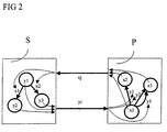
- FIG 2 is a simple technical system with a error-free control FS, states y1, y2, y3 and state transitions x1, x2 shown as state machine.
- the Controller S describes actuators as states.
- a controlled one Process P contains the description of sensors x1 x2, x3 as States x1, x2, x3 and state transitions y1, y2, y3.
- the control S of the system reacts to measured values xj (x1, x2, x3) of sensors X. Therefore sensor data are used in the control S state transitions triggered.
- the conditions are characterized by values yi (y1, y2, y3) of state variables Y, the actuators are assigned.
- the placing of Actuators Y in turn triggers state transitions in the controlled Plant, i.e. in the process P from what is in a modification of the values of the sensors X expresses.
- the state machines of control S and process P perform alternate state transitions.
- the expenditure of one machine is the input of the other machine.
- the interface between the controller and the controlled environment can be automatically recognized in a corresponding description become. Furthermore, it is possible as detailed below is described, such a description the value set can be seen from the individual values (states or state transitions) can accept.
- FIG. 3 symbolically represents a fault model for faulty ones Sensors in a sensor fault model SF and for faulty ones Actuators shown in an actuator error model AF.
- sensors X and actuators Y are connected to the interface between controller S and controlled process P.
- a malfunction of a sensor X leads to the fact that, instead of the correct measured value xj, another, incorrect value x ' j is delivered to the controller S, ie is supplied to the controller S.
- a malfunction of an actuator manifests itself in the setting of an incorrect value y ' i instead of the value yi.
- the state-of-the-art description shows which sensors X and actuators Y are available and which set of values has to be taken into account.
- a non-persistent individual error of a sensor x is described by the following rule:
- FIG. 4 shows the general sensor error model SF from FIG 3 in the event that a non-persistent single error there is a first sensor value x1 such that the first Sensor value x1 either the correct first sensor value x1 or a second sensor value x2 due to a sensor error which would be an incorrect value in this case.
- the second sensor value x2 and a third sensor value x3 measured correctly.
- Controlled process P behaves identically to that in FIG. 4 shown model for the fault case with the first sensor value x1. However, there may be an explicit insertion here Error model between control S and controlled process P can be dispensed with. Because of the adopted intermittent Errors are indicated in the control with x1 State transitions parallel to the state transitions marked with x2 added.
- the second sensor value x2 and the third sensor value x3 are measured correctly. The control behavior for these values is therefore unmodified. Since an intermittent error is assumed, the first sensor value x1 can also be reported correctly, so that these state transitions are retained. If a persistent interchange of the first sensor value x1 with the second sensor value x2 was assumed, edges labeled with x1 would have to be deleted. All state transitions marked with x2 can now be run through with the value x1. A corresponding edge is therefore added to the control S. The controller S reacts to the value x2, but at the point x1 of the process.
- Those states are determined from the difference set at least one condition that can be specified by the user (e.g. Violation of a security requirement) are sufficient violate, depending on the application.
- FIG. 6 shows a technical system in the form of a lifting turntable HD shown a manufacturing cell FZ, with which the Procedure should be presented in more detail.
- the manufacturing cell FZ has a feeding conveyor belt FB, at the end a lifting turntable receives workpieces WS and feeds a robot R.
- the robot R places the workpiece WS in a press PR and after molding there is a leading one Volume WB.
- the manufacturing cell FZ contains corresponding ones Sensors X and actuators Y.
- the HD lifting turntable can be operated using two drives (not shown) in vertical (vmov) and horizontal (hmov) move direction. Any drive can turn into negative (minus) or positive (plus) direction can be controlled or stand still (stop).
- the HD lifting turntable has sensors X for vertical (vpos) and horizontal (hpos) position detection that the Distinguish positions x0 (bottom), x1 (middle) and x2 (top) can.
- another sensor part_on_table (not shown) the presence of a workpiece WS the lifting turntable HD.
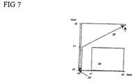
- the starting position AP of the lifting turntable HD is at the bottom, left stop (x0, x0) without workpiece WS (see Figure 7). If a workpiece WS from the feeding conveyor FB to the Lifting turntable HD falls, the target position is ZP of the lifting turntable HD top right (x2, x2).
- the HD lifting turntable must never be in any other horizontal position as x0 (left stop) in combination with the vertical one Take position x0 (below), otherwise it will match the feeder Conveyor belt FB would collide (prohibited area VB).
- CSL defines the control logic of the HD lifting turntable.
- the header of the CSL description declares data types (value ranges) of the state variables.
- the subsequent declaration of the state variables uses these type agreements and also specifies initial values.
- Input variables of the FS control code process states.
- the line "input vpos: posType default x0" declares a state variable with the name "vpos", which can take the values x0, x1 and x2 (the values of the type posType) and whose initial value is x0.
- the transitions serve to describe the Control logic. Transitions are triggered by combinations of values the input variables of the control FS, the process states represent - i.e. the position of the lifting turntable HD in the vertical (vpos) and horizontal (hpos) direction of movement and the presence of a workpiece WS the lifting turntable HD (part_on_table).
- the values of the output variables vmov and hmov are represented by the transitions that the Implement control logic, modified. they describe the states of the controller. Your values are determined by State transitions of the controller, that is, of the controller modified logic modified.
- This information can be obtained automatically from the CSL description be removed. It can be between inputs of the control (Inputs, sensor data) and control outputs (Outputs: actuator commands). Also are the possible values are recognizable (type declarations).
- FSM format F Destinite S tate M achine format
- a process model to describe the reactions of the controlled Process is complementary to the control logic described in CSL required to e.g. Statements about the amount of to enable attainable states. This can be done within the Model checks are carried out with the help of so-called assumptions. Because the model checking is also part of the formal verification error-free control is usually used, are these assumptions usually already available and can be used again in this analysis.
- FIG. 8 shows a state space ZR of the lifting turntable HD and the movement of the error-free lifting turntable HD in the status area ZR shows how he feels after performing the model Checks for the final description of the error-free Control FS with the specified assumptions results.
- each row there is a pair of values for the triple of Variables (vpos, hpos, part_on_table) are shown.
- the Columns are pairs of values for the tuple of the variables (vmov, hmov) with the value sets defined above shown.
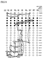
- FIG. 9 the state space ZR of the lifting turntable is HD and the movement of the lifting turntable HD is shown in the status area ZR, if the sensor 'part_on_table' is faulty a workpiece reports WS.
- Figure 9 the same designations are used used as in Figure 8. It can be clearly seen that states can occur for this fault case that cannot be reached in the fault-free system. These states are denoted by VZ in Figure 9.
- the individual sensors x and / or actuators y become failure probabilities assigned, each the probability for the occurrence of an error in the sensor x or describe actuator y.
- the error analysis takes into account the Default probabilities.
- the method is preferably used for all possible errors existing sensors and / or actuators performed.
Claims (11)
- Procédé d'analyse assistée par ordinateur de défaillances de capteurs et / ou d'actionneurs dans un système technique se présentant sous la forme d'une description d'état final, laquelle présente des états du système technique, les étapes suivantes dudit procédé étant exécutées par un ordinateur :a) une description d'état final du système technique est établie pour une défaillance d'un capteur et/ou d'un actionneur du système en cas de défaillance ;b) un premier ensemble d'états accessibles est déterminé pour le système technique exempt de défaillance ;c) un deuxième ensemble d'états accessibles est déterminé pour le système technique défaillant ;d) une différence d'états est établie entre le premier et le deuxième ensembles ;e) des états résultant de la différence des deux ensembles d'états et satisfaisant à des conditions pouvant être prédéfinies peuvent être déterminés.
- Procédé selon la revendication 1,
dans lequel les étapes a) à f) du procédé sont exécutées pour toutes les défaillances possibles de capteurs et / ou d'actionneurs contenus dans le système technique. - Procédé selon la revendication 1 ou 2,dans lequel des probabilités de défaillance sont attribuées aux capteurs et / ou aux actionneurs etdans lequel l'analyse des défaillances se fait compte tenu des probabilités de défaillance.
- Procédé selon l'une des revendications 1 à 3,
dans lequel les étapes b) et c) du procédé se font selon le procédé du « model checking ». - Procédé selon l'une des revendications 1 à 4,
dans lequel une description d'état final d'un processus exécuté par le système technique est prise en compte dans le procédé. - Procédé selon l'une des revendications 1 à 5,
dans lequel la description d'état final est réalisée par un automate fini. - Procédé selon la revendication 6,
dans lequel la description d'état final est réalisée par un automate fini sous la forme d'un « Binary Decision Diagram » (BDD). - Utilisation du procédé selon l'une des revendications 1 à 7 dans le cadre du « Rapid Prototyping » du système technique.
- Utilisation du procédé selon l'une des revendications 1 à 7 dans le cadre du diagnostic de défaillance du système technique.
- Utilisation du procédé selon l'une des revendications 1 à 7 aux fins de générer des cas d'essai critiques pour une mise en service ou un test de système du système technique.
- Utilisation du procédé selon l'une des revendications 1 à 7 aux fins de la maintenance préventive du système technique.
Applications Claiming Priority (3)
| Application Number | Priority Date | Filing Date | Title |
|---|---|---|---|
| DE19709956 | 1997-03-11 | ||
| DE19709956 | 1997-03-11 | ||
| PCT/DE1998/000633 WO1998040796A1 (fr) | 1997-03-11 | 1998-03-03 | Procede d'analyse assistee par ordinateur de defaillances de capteurs et/ou d'actionneurs dans un systeme technique |
Publications (2)
| Publication Number | Publication Date |
|---|---|
| EP0966703A1 EP0966703A1 (fr) | 1999-12-29 |
| EP0966703B1 true EP0966703B1 (fr) | 2002-10-02 |
Family
ID=7822948
Family Applications (1)
| Application Number | Title | Priority Date | Filing Date |
|---|---|---|---|
| EP98916847A Expired - Lifetime EP0966703B1 (fr) | 1997-03-11 | 1998-03-03 | Procede d'analyse assistee par ordinateur de defaillances de capteurs et/ou d'actionneurs dans un systeme technique |
Country Status (4)
| Country | Link |
|---|---|
| US (1) | US6907386B1 (fr) |
| EP (1) | EP0966703B1 (fr) |
| DE (1) | DE59805802D1 (fr) |
| WO (1) | WO1998040796A1 (fr) |
Families Citing this family (21)
| Publication number | Priority date | Publication date | Assignee | Title |
|---|---|---|---|---|
| DE10017708B4 (de) | 2000-04-04 | 2008-02-14 | Technische Universität Dresden | Verfahren zum Steuern von Mechanismen und technischen Systemen, Einrichtung und Steuerungssoftware |
| US7539977B1 (en) * | 2005-01-21 | 2009-05-26 | Xilinx, Inc. | Automatic bug isolation in computer programming languages |
| US20110054639A1 (en) * | 2008-02-01 | 2011-03-03 | Luca Pazzi | Method for ensuring safety and liveness rules in a state based design |
| US8645108B2 (en) * | 2010-08-17 | 2014-02-04 | Fujitsu Limited | Annotating binary decision diagrams representing sensor data |
| US8874607B2 (en) | 2010-08-17 | 2014-10-28 | Fujitsu Limited | Representing sensor data as binary decision diagrams |
| US8572146B2 (en) | 2010-08-17 | 2013-10-29 | Fujitsu Limited | Comparing data samples represented by characteristic functions |
| US8583718B2 (en) | 2010-08-17 | 2013-11-12 | Fujitsu Limited | Comparing boolean functions representing sensor data |
| US9138143B2 (en) | 2010-08-17 | 2015-09-22 | Fujitsu Limited | Annotating medical data represented by characteristic functions |
| US8930394B2 (en) | 2010-08-17 | 2015-01-06 | Fujitsu Limited | Querying sensor data stored as binary decision diagrams |
| US9002781B2 (en) | 2010-08-17 | 2015-04-07 | Fujitsu Limited | Annotating environmental data represented by characteristic functions |
| US9075908B2 (en) | 2011-09-23 | 2015-07-07 | Fujitsu Limited | Partitioning medical binary decision diagrams for size optimization |
| US9176819B2 (en) | 2011-09-23 | 2015-11-03 | Fujitsu Limited | Detecting sensor malfunctions using compression analysis of binary decision diagrams |
| US8909592B2 (en) | 2011-09-23 | 2014-12-09 | Fujitsu Limited | Combining medical binary decision diagrams to determine data correlations |
| US8719214B2 (en) | 2011-09-23 | 2014-05-06 | Fujitsu Limited | Combining medical binary decision diagrams for analysis optimization |
| US8838523B2 (en) | 2011-09-23 | 2014-09-16 | Fujitsu Limited | Compression threshold analysis of binary decision diagrams |
| US8781995B2 (en) | 2011-09-23 | 2014-07-15 | Fujitsu Limited | Range queries in binary decision diagrams |
| US9177247B2 (en) | 2011-09-23 | 2015-11-03 | Fujitsu Limited | Partitioning medical binary decision diagrams for analysis optimization |
| US8812943B2 (en) * | 2011-09-23 | 2014-08-19 | Fujitsu Limited | Detecting data corruption in medical binary decision diagrams using hashing techniques |
| US8620854B2 (en) | 2011-09-23 | 2013-12-31 | Fujitsu Limited | Annotating medical binary decision diagrams with health state information |
| US11351383B2 (en) | 2018-04-30 | 2022-06-07 | Medtronic, Inc. | Left ventricular capture and synchronization verification using a single multi-electrode coronary sinus lead |
| DE102022203124A1 (de) | 2022-03-30 | 2023-10-05 | Robert Bosch Gesellschaft mit beschränkter Haftung | Computer-implementiertes System und Verfahren zum Überwachen der Funktionsfähigkeit einer automatisierten Fahrfunktion |
Family Cites Families (26)
| Publication number | Priority date | Publication date | Assignee | Title |
|---|---|---|---|---|
| DE3445030A1 (de) * | 1984-12-11 | 1986-06-19 | Philips Patentverwaltung Gmbh, 2000 Hamburg | Verkehrssimulationseinrichtung zum testen von vermittlungsanlagen unter beruecksichtigung der teilnehmer-system-interaktion |
| IL78542A0 (en) * | 1986-04-18 | 1986-08-31 | Yeda Res & Dev | Electronic controller based on the use of statecharts as an abstract model |
| DE3825280A1 (de) * | 1988-07-26 | 1990-02-01 | Bayerische Motoren Werke Ag | Steuersystem fuer stelleinrichtungen eines kraftfahrzeugs |
| US5161115A (en) * | 1989-09-12 | 1992-11-03 | Kabushiki Kaisha Toshiba | System test apparatus for verifying operability |
| JPH0820284B2 (ja) * | 1989-10-23 | 1996-03-04 | 株式会社小松製作所 | 故障診断装置 |
| US5038307A (en) * | 1989-10-30 | 1991-08-06 | At&T Bell Laboratories | Measurement of performance of an extended finite state machine |
| WO1992018944A1 (fr) * | 1991-04-17 | 1992-10-29 | Siemens Aktiengesellschaft | Procede pour la verification de systemes traitant des donnees |
| US5301100A (en) * | 1991-04-29 | 1994-04-05 | Wagner Ferdinand H | Method of and apparatus for constructing a control system and control system created thereby |
| US5201296A (en) * | 1992-03-30 | 1993-04-13 | Caterpillar Inc. | Control system for an internal combustion engine |
| GB9209346D0 (en) * | 1992-04-30 | 1992-06-17 | Sharp Kk | Machine translation system |
| US5717394A (en) * | 1993-02-10 | 1998-02-10 | Ricoh Company Ltd. | Method and apparatus for encoding and decoding data |
| US5671141A (en) * | 1993-04-05 | 1997-09-23 | Ford Global Technologies, Inc. | Computer program architecture for onboard vehicle diagnostic system |
| US5481717A (en) * | 1993-04-12 | 1996-01-02 | Kabushiki Kaisha Toshiba | Logic program comparison method for verifying a computer program in relation to a system specification |
| DE4317538A1 (de) * | 1993-05-26 | 1994-12-01 | Siemens Ag | Regeleinrichtung |
| DE69326072T2 (de) * | 1993-11-02 | 1999-12-23 | Bull Sa | Verfahren zur Prüfung eines sequentiellen endlichen Automaten |
| CA2147536A1 (fr) * | 1994-06-01 | 1995-12-02 | Gerard Johan Holzmann | Systeme de verification a la volee avec reduction de l'espace de recherche par ordre partiel |
| DE19513801A1 (de) * | 1995-04-11 | 1996-10-17 | Siemens Ag | Verfahren zur automatischen Erzeugung einer Steuerung |
| US5831853A (en) * | 1995-06-07 | 1998-11-03 | Xerox Corporation | Automatic construction of digital controllers/device drivers for electro-mechanical systems using component models |
| US5680332A (en) * | 1995-10-30 | 1997-10-21 | Motorola, Inc. | Measurement of digital circuit simulation test coverage utilizing BDDs and state bins |
| EP0828215B1 (fr) * | 1996-09-05 | 2002-05-15 | Siemens Aktiengesellschaft | Procédé de vérification par un ordinateur d'un programme écrit dans un langage pour automate programmable |
| DE69838441T2 (de) * | 1997-02-28 | 2008-02-14 | Fujitsu Ltd., Kawasaki | Verfahren und Anordnung zur Verifizierung logischer Geräte |
| US6144885A (en) * | 1997-06-03 | 2000-11-07 | Scarrah; Warren P. | Method for the interactive improvement of manufacturing processes |
| US6059837A (en) * | 1997-12-30 | 2000-05-09 | Synopsys, Inc. | Method and system for automata-based approach to state reachability of interacting extended finite state machines |
| US6094151A (en) * | 1998-01-05 | 2000-07-25 | Ricoh Company, Ltd. | Apparatus and method for finite state machine coding of information selecting most probable state subintervals |
| US6526551B2 (en) * | 2000-06-30 | 2003-02-25 | University Of Southern California | Formal verification of a logic design through implicit enumeration of strongly connected components |
| US6424444B1 (en) * | 2001-01-29 | 2002-07-23 | Stratalight Communications, Inc. | Transmission and reception of duobinary multilevel pulse-amplitude-modulated optical signals using finite-state machine-based encoder |
-
1998
- 1998-03-03 US US09/367,778 patent/US6907386B1/en not_active Expired - Lifetime
- 1998-03-03 WO PCT/DE1998/000633 patent/WO1998040796A1/fr active IP Right Grant
- 1998-03-03 EP EP98916847A patent/EP0966703B1/fr not_active Expired - Lifetime
- 1998-03-03 DE DE59805802T patent/DE59805802D1/de not_active Expired - Lifetime
Also Published As
| Publication number | Publication date |
|---|---|
| WO1998040796A1 (fr) | 1998-09-17 |
| DE59805802D1 (de) | 2002-11-07 |
| US6907386B1 (en) | 2005-06-14 |
| EP0966703A1 (fr) | 1999-12-29 |
Similar Documents
| Publication | Publication Date | Title |
|---|---|---|
| EP0966703B1 (fr) | Procede d'analyse assistee par ordinateur de defaillances de capteurs et/ou d'actionneurs dans un systeme technique | |
| EP0852759B1 (fr) | Procede de conception pour systemes industriels et systemes de construction, et systeme de planification assiste par ordinateur a utiliser dans le cadre dudit procede | |
| EP1192543B1 (fr) | Procede et systeme pour determiner l'arborescence de defaillances d'un systeme technique, produit de programme informatique et support d'information lisible par ordinateur associe | |
| EP2122428B1 (fr) | Procédé et système de détermination de paramètres de fiabilité d'une installation technique | |
| EP0753168B1 (fr) | Procede pour le diagnostic automatique de defaillances | |
| DE602004007209T2 (de) | Sicherheitssteuerung zur Bereitstellung einer schnellen Wiederherstellung von Sicherheitsprogrammdaten | |
| WO2005109136A1 (fr) | Systeme de diagnostic assiste par ordinateur a base d'heuristiques et de topologies systeme | |
| EP3650970B1 (fr) | Procédé et dispositif de simulation assistée par ordinateur d'un système technique modulaire | |
| DE102017211433A1 (de) | Verfahren zum Durchführen eines Funktionstests eines Steuergeräts in einem Hardware-in-the-Loop-Test, HIL-Test, sowie HIL-Prüfstand und Steuergerät | |
| EP1137972A2 (fr) | Systeme d'automatisation pour la realisation de taches definies dans le cadre de la technique des processus, et procede associe | |
| EP3207386B1 (fr) | Contrôle d'un module fonctionnel d'un système d'automatisation | |
| DE10133670A1 (de) | Verfahren zur automatischen Erzeugung einer Wissensbasis für ein Diagnosesystem | |
| EP3961334B1 (fr) | Procédé de modélisation d'un arbre de défaillances de composants pour un circuit électrique | |
| WO1999017176A1 (fr) | Module pour etablir un diagnostic destine a des systemes a commande electrique, et dispositif pour etablir un diagnostic d'un systeme global | |
| EP3933593A1 (fr) | Procédé et programme informatique destinés aux essais d'un système technique | |
| DE102020206327A1 (de) | Verfahren und Vorrichtung zum Prüfen eines technischen Systems | |
| EP1505399B1 (fr) | Procédé pour génération de données de test pour test fonctionnel d'un circuit de traitement de données | |
| DE10325513B4 (de) | Verfahren und Vorrichtung zum Erstellen eines Verhaltensaspekts einer Schaltung zur formalen Verifikation | |
| WO1999038024A1 (fr) | Procede d'optimisation de specifications de controle et de minimisation de logiciels de controle assistees par ordinateur | |
| EP3828655B1 (fr) | Procédé et dispositif de détermination des causes d'une défaillance dans un circuit électrique | |
| WO2014012776A1 (fr) | Reconfiguration automatisée d'un circuit de réglage à événements discrets | |
| EP1958101A1 (fr) | Systeme et procede de verification automatique de resultats de conception | |
| EP3173928A1 (fr) | Procédé et dispositif de contrôle d'un arbre de défaillances de composant | |
| WO2015078601A1 (fr) | Dispositif, procédé de génération automatique d'un modèle fem et régulateur | |
| DE102020205980A1 (de) | Verfahren und Vorrichtung zum Simulieren eines technischen Systems |
Legal Events
| Date | Code | Title | Description |
|---|---|---|---|
| PUAI | Public reference made under article 153(3) epc to a published international application that has entered the european phase |
Free format text: ORIGINAL CODE: 0009012 |
|
| 17P | Request for examination filed |
Effective date: 19990903 |
|
| AK | Designated contracting states |
Kind code of ref document: A1 Designated state(s): DE FR GB |
|
| 17Q | First examination report despatched |
Effective date: 20010703 |
|
| GRAG | Despatch of communication of intention to grant |
Free format text: ORIGINAL CODE: EPIDOS AGRA |
|
| GRAG | Despatch of communication of intention to grant |
Free format text: ORIGINAL CODE: EPIDOS AGRA |
|
| GRAH | Despatch of communication of intention to grant a patent |
Free format text: ORIGINAL CODE: EPIDOS IGRA |
|
| GRAH | Despatch of communication of intention to grant a patent |
Free format text: ORIGINAL CODE: EPIDOS IGRA |
|
| GRAA | (expected) grant |
Free format text: ORIGINAL CODE: 0009210 |
|
| AK | Designated contracting states |
Kind code of ref document: B1 Designated state(s): DE FR GB |
|
| REG | Reference to a national code |
Ref country code: GB Ref legal event code: FG4D Free format text: NOT ENGLISH |
|
| REF | Corresponds to: |
Ref document number: 59805802 Country of ref document: DE Date of ref document: 20021107 |
|
| GBT | Gb: translation of ep patent filed (gb section 77(6)(a)/1977) |
Effective date: 20030107 |
|
| ET | Fr: translation filed | ||
| PLBE | No opposition filed within time limit |
Free format text: ORIGINAL CODE: 0009261 |
|
| STAA | Information on the status of an ep patent application or granted ep patent |
Free format text: STATUS: NO OPPOSITION FILED WITHIN TIME LIMIT |
|
| 26N | No opposition filed |
Effective date: 20030703 |
|
| PG25 | Lapsed in a contracting state [announced via postgrant information from national office to epo] |
Ref country code: DE Free format text: LAPSE BECAUSE OF NON-PAYMENT OF DUE FEES Effective date: 20111001 |
|
| REG | Reference to a national code |
Ref country code: FR Ref legal event code: PLFP Year of fee payment: 19 |
|
| REG | Reference to a national code |
Ref country code: FR Ref legal event code: PLFP Year of fee payment: 20 |
|
| PGFP | Annual fee paid to national office [announced via postgrant information from national office to epo] |
Ref country code: FR Payment date: 20170316 Year of fee payment: 20 |
|
| PGFP | Annual fee paid to national office [announced via postgrant information from national office to epo] |
Ref country code: GB Payment date: 20170313 Year of fee payment: 20 |
|
| PGFP | Annual fee paid to national office [announced via postgrant information from national office to epo] |
Ref country code: DE Payment date: 20170519 Year of fee payment: 20 |
|
| REG | Reference to a national code |
Ref country code: DE Ref legal event code: R071 Ref document number: 59805802 Country of ref document: DE |
|
| REG | Reference to a national code |
Ref country code: GB Ref legal event code: PE20 Expiry date: 20180302 |
|
| PG25 | Lapsed in a contracting state [announced via postgrant information from national office to epo] |
Ref country code: GB Free format text: LAPSE BECAUSE OF EXPIRATION OF PROTECTION Effective date: 20180302 |