EP0966612B1 - Raccord d'entrainement, tributaire du sens de la marche, entre le rotor d'un moteur synchrone a aimant permanent et la piece active - Google Patents
Raccord d'entrainement, tributaire du sens de la marche, entre le rotor d'un moteur synchrone a aimant permanent et la piece active Download PDFInfo
- Publication number
- EP0966612B1 EP0966612B1 EP98965291A EP98965291A EP0966612B1 EP 0966612 B1 EP0966612 B1 EP 0966612B1 EP 98965291 A EP98965291 A EP 98965291A EP 98965291 A EP98965291 A EP 98965291A EP 0966612 B1 EP0966612 B1 EP 0966612B1
- Authority
- EP
- European Patent Office
- Prior art keywords
- tooth
- rotor
- coupling according
- working part
- rigidly coupled
- Prior art date
- Legal status (The legal status is an assumption and is not a legal conclusion. Google has not performed a legal analysis and makes no representation as to the accuracy of the status listed.)
- Expired - Lifetime
Links
Images


Classifications
-
- F—MECHANICAL ENGINEERING; LIGHTING; HEATING; WEAPONS; BLASTING
- F16—ENGINEERING ELEMENTS AND UNITS; GENERAL MEASURES FOR PRODUCING AND MAINTAINING EFFECTIVE FUNCTIONING OF MACHINES OR INSTALLATIONS; THERMAL INSULATION IN GENERAL
- F16D—COUPLINGS FOR TRANSMITTING ROTATION; CLUTCHES; BRAKES
- F16D59/00—Self-acting brakes, e.g. coming into operation at a predetermined speed
-
- F—MECHANICAL ENGINEERING; LIGHTING; HEATING; WEAPONS; BLASTING
- F04—POSITIVE - DISPLACEMENT MACHINES FOR LIQUIDS; PUMPS FOR LIQUIDS OR ELASTIC FLUIDS
- F04D—NON-POSITIVE-DISPLACEMENT PUMPS
- F04D13/00—Pumping installations or systems
- F04D13/02—Units comprising pumps and their driving means
- F04D13/021—Units comprising pumps and their driving means containing a coupling
- F04D13/022—Units comprising pumps and their driving means containing a coupling a coupling allowing slip, e.g. torque converter
-
- H—ELECTRICITY
- H02—GENERATION; CONVERSION OR DISTRIBUTION OF ELECTRIC POWER
- H02K—DYNAMO-ELECTRIC MACHINES
- H02K7/00—Arrangements for handling mechanical energy structurally associated with dynamo-electric machines, e.g. structural association with mechanical driving motors or auxiliary dynamo-electric machines
- H02K7/10—Structural association with clutches, brakes, gears, pulleys or mechanical starters
- H02K7/118—Structural association with clutches, brakes, gears, pulleys or mechanical starters with starting devices
- H02K7/1185—Structural association with clutches, brakes, gears, pulleys or mechanical starters with starting devices with a mechanical one-way direction control, i.e. with means for reversing the direction of rotation of the rotor
-
- Y—GENERAL TAGGING OF NEW TECHNOLOGICAL DEVELOPMENTS; GENERAL TAGGING OF CROSS-SECTIONAL TECHNOLOGIES SPANNING OVER SEVERAL SECTIONS OF THE IPC; TECHNICAL SUBJECTS COVERED BY FORMER USPC CROSS-REFERENCE ART COLLECTIONS [XRACs] AND DIGESTS
- Y10—TECHNICAL SUBJECTS COVERED BY FORMER USPC
- Y10T—TECHNICAL SUBJECTS COVERED BY FORMER US CLASSIFICATION
- Y10T403/00—Joints and connections
- Y10T403/10—Selectively engageable hub to shaft connection
Claims (16)
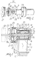
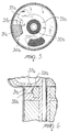
- Raccord d'entraínement tributaire du sens de la marche (30, 116, 216) entre le rotor (14, 110, 210) d'un moteur synchrone à aimant permanent et une pièce active (24, 115), comprenant : au moins une première dent d'entraínement excentrique (31, 31a, 120, 217) qui est couplée de manière rigide à un premier élément parmi le rotor et la pièce active (14, 210, 117) entre lesquels le mouvement doit être transmis ; un élément (33, 119, 222) qui permet le mouvement tributaire du sens de la marche ayant au moins un élément en porte à faux (36, 121, 232) agencé de manière périphérique à proximité d'une paroi cylindrique dont il suit partiellement la forme, ladite paroi étant formée par un logement (25, 111, 233) dans lequel le rotor (14, 110, 210) est agencé, le logement (25, 111, 233) étant immobile au démarrage par rapport au composant motorisé (14, 110, 210) ; et au moins une seconde dent excentrique (40, 127, 221) rigidement couplée à un second élément parmi le rotor et la pièce active (29, 110, 219) entre lesquels le mouvement doit être transmis dans une position telle que le passage entre le rotor (14, 110, 210) et la pièce active (24, 115) oblige la seconde dent (40, 127, 210) à interagir avec ladite première dent (31, 31a, 120, 217) dans une première direction de rotation et à interagir avec ledit élément en porte à faux (36, 121, 232) dans la seconde direction de rotation opposée, produisant une poussée radiale vers l'extérieur qui fait fléchir ledit élément en porte à faux contre ladite paroi cylindrique, en la bloquant, caractérisé en ce que ledit élément (33, 119, 222) qui permet le mouvement tributaire du sens de la marche ayant au moins un élément en porte à faux (36, 121, 232), est prévu comme un composant séparé entre le rotor et la pièce active (14, 210, 117) et est fabriqué à partir d'un matériau élastomère.
- Raccord selon la revendication 1, caractérisé en ce qu'il comprend un élément en porte à faux (36) qui dépasse d'un élément annulaire (33) constituant ledit élément qui permet le mouvement tributaire du sens de la marche, qui est couplé pour transmission du mouvement à ladite première dent (31).
- Raccord selon la revendication 2, caractérisé en ce que ledit élément annulaire (33) est agencé de manière radiale et interne par rapport à ladite première dent excentrique (31) et possède deux pattes (34, 35) agencées de chaque côté de celle-ci, ledit élément en porte à faux (38) étant monolithique avec Tune (34) desdites pattes et dépassant de celle-ci.
- Raccord selon la revendication 1, caractérisé en ce que ledit élément en porte à faux (36) est interposé, suite à la rotation dans ladite seconde direction de rotation, avec l'une de ses parties (37, 38) entre ladite seconde dent (40) et ladite paroi.
- Raccord selon la revendication 1, caractérisé en ce que ladite première dent (31) est couplée de manière rigide au rotor (14) du moteur, et en ce que ledit élément en porte à faux (36) est couplé pour transmission de mouvement à ladite première dent (31), ladite paroi cylindrique étant couplée de manière rigide à la pièce active (24).
- Raccord selon la revendication 5, caractérisé en ce que ladite seconde dent (40) est couplée de manière monolithique à un impulseur à lamelles (29) qui sert de pompe et est orienté en face d'un impulseur à lamelles (27, 28) qui sert de turbine et qui est couplé de manière rigide à ladite paroi étant donné qu'il fait partie, conjointement avec ladite paroi, du logement hermétique rotatif (25) dans lequel ledit rotor (14) est agencé.
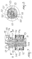
- Raccord selon la revendication 1, caractérisé en ce que ledit élément en porte à faux (121) est monolithique avec ladite première dent (120).
- Raccord selon la revendication 7, caractérisé en ce que ladite première dent (120) est couplée de manière rigide à ladite pièce active (115) et ladite seconde dent (127) est couplée de manière rigide audit rotor (110).
- Raccord selon la revendication 8, caractérisé en ce que ladite pièce active (115) est dotée d'un moyeu (117) qui supporte un élément élastomère annulaire (119) à partir duquel ladite première dent (120) dépasse de manière radiale, ledit élément annulaire (119) qui supporte ledit élément en porte à faux (121) est couplé de manière rigide à celui-ci, et se trouve de manière périphérique à proximité de la paroi cylindrique d'une chambre en forme de tube (111) dans laquelle ledit rotor (110) est placé et qui fait partie de la structure de support dudit rotor (110).
- Raccord selon la revendication 9, caractérisé en ce que ladite seconde dent (127) est monolithique avec ledit rotor (120).
- Raccord selon la revendication 9, caractérisé en ce que ledit élément annulaire (119) est muni intérieurement de rainures (123) qui sont formées de manière complémentaire par rapport aux rainures (124) dudit moyeu (117) qui sont adaptées pour coupler de manière rigide l'élément annulaire (119) audit moyeu (117) pour la rotation de l'assemblage, ledit élément annulaire (119) étant également muni de creux axiaux (125) qui constituent des sièges pour positionner des parties élevées (126) dudit moyeu (117) pour le positionner correctement et le fixer de manière axiale.
- Raccord selon la revendication 11, caractérisé en ce qu'au moins l'extrémité libre dudit élément en porte à faux (36, 121) est sensiblement en forme de coin.
- Raccord selon la revendication 1, caractérisé en ce qu'entre ledit élément élastomère annulaire (33a) et celui (14, 31a) desdits deux composants qui peut être en mouvement relatif avec celui-ci au démarrage, du côté qui correspond à la direction de rotation correcte, on trouve des pièces (37a, 38a) qui sont en contact coulissant selon un angle prédéterminé de manière à procurer un effet de frottement afin d'amortir le choc du démarrage.
- Raccord selon la revendication 13, caractérisé en ce que l'angle couvert par ladite première dent (31a) est inférieur à l'espace angulaire situé entre lesdites pattes (34a, 35a) qui dépassent dudit élément annulaire (33a) afin de procurer un mouvement relatif contrôlé par frottement au démarrage.
- Raccord selon la revendication 1, caractérisé en ce que ladite première dent (217) est couplée de manière rigide au rotor (210) du moteur et ladite seconde dent (221) est couplée à la pièce active, un volet courbe (218) dépassant dudit rotor (210), auquel il est couplé de manière rigide, à partir d'une position qui est tournée par rapport à ladite première dent (217), ledit volet (218) formant une extension de la structure externe du rotor (210) et la bloquant, lorsque ladite première dent (217) actionne ladite seconde dent (221) couplée à la pièce active, entre ledit élément en porte à faux (232) et ladite paroi cylindrique (233) afin d'empêcher tout contact, ladite paroi cylindrique (233) étant fixée par rapport audit composant motorisé (210).
- Raccord selon la revendication 6, caractérisé en ce que ledit logement (25), dans lequel le rotor (14) est agencé, est fixé par rapport au stator (11).
Applications Claiming Priority (3)
| Application Number | Priority Date | Filing Date | Title |
|---|---|---|---|
| ITPD980003 | 1998-01-08 | ||
| IT98PD000003A ITPD980003A1 (it) | 1998-01-08 | 1998-01-08 | Giunto di trascinamento monodirezionale fra il rotore di un motore sincrono a magneti permanenti e l'organo operatore |
| PCT/EP1998/008518 WO1999035403A1 (fr) | 1998-01-08 | 1998-12-30 | Raccord d'entrainement, tributaire du sens de la marche, entre le rotor d'un moteur synchrone a aimant permanent et la piece active |
Publications (2)
| Publication Number | Publication Date |
|---|---|
| EP0966612A1 EP0966612A1 (fr) | 1999-12-29 |
| EP0966612B1 true EP0966612B1 (fr) | 2003-07-23 |
Family
ID=11392004
Family Applications (1)
| Application Number | Title | Priority Date | Filing Date |
|---|---|---|---|
| EP98965291A Expired - Lifetime EP0966612B1 (fr) | 1998-01-08 | 1998-12-30 | Raccord d'entrainement, tributaire du sens de la marche, entre le rotor d'un moteur synchrone a aimant permanent et la piece active |
Country Status (7)
| Country | Link |
|---|---|
| US (1) | US6217452B1 (fr) |
| EP (1) | EP0966612B1 (fr) |
| AT (1) | ATE245770T1 (fr) |
| AU (1) | AU2054999A (fr) |
| DE (1) | DE69816597T2 (fr) |
| IT (1) | ITPD980003A1 (fr) |
| WO (1) | WO1999035403A1 (fr) |
Families Citing this family (12)
| Publication number | Priority date | Publication date | Assignee | Title |
|---|---|---|---|---|
| ITPD980058A1 (it) * | 1998-03-19 | 1999-09-19 | Askoll Holding Srl | Dispositivo di trascinamento, con angolo di libera rotazione ampliato fra il motore sincrono a magneti permanenti e l'organo operatore |
| US6478555B1 (en) * | 1999-06-16 | 2002-11-12 | Lg Electronics, Inc. | Apparatus for controlling noise and vibration for drain pump |
| GB2353330B (en) * | 1999-08-04 | 2003-05-28 | Pet Mate Ltd | Pond pump |
| US6685446B2 (en) | 2000-07-06 | 2004-02-03 | Askoll Holding S.R.L. | Monodirectional impeller with flexible vanes |
| US6932319B2 (en) * | 2001-06-13 | 2005-08-23 | Tritex Corporation | Linear valve actuator |
| EP1357297B1 (fr) * | 2002-04-24 | 2011-07-20 | Grundfos A/S | Dispositif de pompe centrifuge entraînée par un moteur électrique |
| DE60306594T2 (de) | 2002-09-03 | 2006-11-16 | Emerson Appliance Motors Europe S.R.L., Moncalieri | Kreiselpumpe für Haushaltsgeräte |
| CN100465455C (zh) * | 2003-11-26 | 2009-03-04 | 普拉塞特股份有限公司 | 尤其用于家用电器中的离心泵 |
| EP1553681B1 (fr) | 2003-12-31 | 2017-03-15 | Askoll Holding S.r.l. | Dispositif de couplage entre un rotor de moteur synchrone à aimants permanents et un organe de travail |
| DE102004056508B3 (de) * | 2004-11-24 | 2006-03-09 | Hanning Elektro-Werke Gmbh & Co. Kg | Synchronmotor mit Anlaufeinrichtung |
| CN2916195Y (zh) * | 2006-01-26 | 2007-06-27 | 江门市汉宇电器有限公司 | 一种离心式排水泵 |
| EP2042074B1 (fr) | 2007-09-27 | 2010-11-10 | Electrolux Home Products Corporation N.V. | Pompe rotative, en particulier pour lave-vaisselle ou pour lave-linge |
Family Cites Families (10)
| Publication number | Priority date | Publication date | Assignee | Title |
|---|---|---|---|---|
| US770641A (en) * | 1904-09-20 | Clutch | ||
| GB361656A (en) * | 1930-12-13 | 1931-11-26 | Austin John Morgan Jones | An improved brake for preventing reverse motion |
| US1968771A (en) * | 1933-04-03 | 1934-07-31 | William A Jex | One-way clutch |
| US2224935A (en) * | 1939-02-02 | 1940-12-17 | William F Schultz | Starting motor drive |
| DE1230531B (de) * | 1965-04-10 | 1966-12-15 | Dornier System Gmbh | Bremseinrichtung fuer Seilschleppwinden, insbesondere in Luftziel-Schleppsystemen |
| US3581857A (en) * | 1969-09-24 | 1971-06-01 | North American Clutch Corp | One-way centrifugal clutch |
| DE3345323A1 (de) * | 1983-12-15 | 1985-06-27 | Gunther Eheim Fabrik Elektromechanischer Erzeugnisse, 7301 Deizisau | Motorpumpenaggregat |
| US4750872A (en) * | 1985-07-01 | 1988-06-14 | Easthorpe Investments Ltd. | Centrifugal pump with damped motor connection |
| US4803855A (en) * | 1987-08-10 | 1989-02-14 | Whirlpool Corporation | Single shaft agitate and spin drive for automatic washer |
| JPH07158663A (ja) * | 1993-12-07 | 1995-06-20 | Nikon Corp | 一方向クラッチ |
-
1998
- 1998-01-08 IT IT98PD000003A patent/ITPD980003A1/it unknown
- 1998-12-30 US US09/380,568 patent/US6217452B1/en not_active Expired - Lifetime
- 1998-12-30 WO PCT/EP1998/008518 patent/WO1999035403A1/fr active IP Right Grant
- 1998-12-30 AU AU20549/99A patent/AU2054999A/en not_active Abandoned
- 1998-12-30 AT AT98965291T patent/ATE245770T1/de not_active IP Right Cessation
- 1998-12-30 DE DE69816597T patent/DE69816597T2/de not_active Expired - Lifetime
- 1998-12-30 EP EP98965291A patent/EP0966612B1/fr not_active Expired - Lifetime
Also Published As
| Publication number | Publication date |
|---|---|
| WO1999035403A1 (fr) | 1999-07-15 |
| ITPD980003A1 (it) | 1999-07-08 |
| ITPD980003A0 (it) | 1998-01-08 |
| DE69816597T2 (de) | 2004-04-08 |
| AU2054999A (en) | 1999-07-26 |
| EP0966612A1 (fr) | 1999-12-29 |
| ATE245770T1 (de) | 2003-08-15 |
| US6217452B1 (en) | 2001-04-17 |
| DE69816597D1 (de) | 2003-08-28 |
Similar Documents
| Publication | Publication Date | Title |
|---|---|---|
| US7097434B2 (en) | Device for transmitting motion between the rotor of a synchronous permanent-magnet motor and the working part, having an increased free rotation angle | |
| EP0966612B1 (fr) | Raccord d'entrainement, tributaire du sens de la marche, entre le rotor d'un moteur synchrone a aimant permanent et la piece active | |
| EP1908959B1 (fr) | Dispositif de couplage de turbine de pompe à mouvement libre limité | |
| EP1365157B1 (fr) | Rotor monodirectionnel destiné à des electro-pompes centrifuges equipées d'un moteur synchrone à aimants permanents | |
| US5668425A (en) | Startup device for the rotor of a permanent-magnet synchronous motor | |
| US20090251013A1 (en) | Electric Motor for Rotation and Axial Movement | |
| EP3135921B1 (fr) | Pompe à liquide, moteur et son unité manchon d'arbre | |
| CN110873061A (zh) | 泵体及用于泵体的转子组件的制造方法 | |
| GB2425156A (en) | Bearing arrangement for an electric motor | |
| US20080219875A1 (en) | Magnetic drive vane pump | |
| US6478555B1 (en) | Apparatus for controlling noise and vibration for drain pump | |
| US6335579B1 (en) | Electric motor with permanent-magnet rotor having viscous shaft coupling | |
| EP0945622B1 (fr) | Pompe à moteur éléctrique synchrone avec silencieux | |
| US20170271968A1 (en) | Electric motor and electric apparatus using same | |
| KR20040089337A (ko) | 브러시리스 모터용 회전자 및 이의 제조방법 | |
| EP3926172B1 (fr) | Moteur, pompe et dispositif de lavage | |
| JP4850665B2 (ja) | 流体ポンプ装置 | |
| JP2003169440A (ja) | モータ |
Legal Events
| Date | Code | Title | Description |
|---|---|---|---|
| PUAI | Public reference made under article 153(3) epc to a published international application that has entered the european phase |
Free format text: ORIGINAL CODE: 0009012 |
|
| AK | Designated contracting states |
Kind code of ref document: A1 Designated state(s): AT CH DE DK ES FR GB IT LI NL SE |
|
| 17P | Request for examination filed |
Effective date: 19991223 |
|
| 17Q | First examination report despatched |
Effective date: 20020409 |
|
| GRAH | Despatch of communication of intention to grant a patent |
Free format text: ORIGINAL CODE: EPIDOS IGRA |
|
| GRAH | Despatch of communication of intention to grant a patent |
Free format text: ORIGINAL CODE: EPIDOS IGRA |
|
| GRAA | (expected) grant |
Free format text: ORIGINAL CODE: 0009210 |
|
| AK | Designated contracting states |
Designated state(s): AT CH DE DK ES FR GB IT LI NL SE |
|
| PG25 | Lapsed in a contracting state [announced via postgrant information from national office to epo] |
Ref country code: NL Free format text: LAPSE BECAUSE OF FAILURE TO SUBMIT A TRANSLATION OF THE DESCRIPTION OR TO PAY THE FEE WITHIN THE PRESCRIBED TIME-LIMIT Effective date: 20030723 Ref country code: LI Free format text: LAPSE BECAUSE OF FAILURE TO SUBMIT A TRANSLATION OF THE DESCRIPTION OR TO PAY THE FEE WITHIN THE PRESCRIBED TIME-LIMIT Effective date: 20030723 Ref country code: CH Free format text: LAPSE BECAUSE OF FAILURE TO SUBMIT A TRANSLATION OF THE DESCRIPTION OR TO PAY THE FEE WITHIN THE PRESCRIBED TIME-LIMIT Effective date: 20030723 Ref country code: AT Free format text: LAPSE BECAUSE OF FAILURE TO SUBMIT A TRANSLATION OF THE DESCRIPTION OR TO PAY THE FEE WITHIN THE PRESCRIBED TIME-LIMIT Effective date: 20030723 |
|
| REG | Reference to a national code |
Ref country code: GB Ref legal event code: FG4D |
|
| REG | Reference to a national code |
Ref country code: CH Ref legal event code: EP |
|
| REF | Corresponds to: |
Ref document number: 69816597 Country of ref document: DE Date of ref document: 20030828 Kind code of ref document: P |
|
| PG25 | Lapsed in a contracting state [announced via postgrant information from national office to epo] |
Ref country code: SE Free format text: LAPSE BECAUSE OF FAILURE TO SUBMIT A TRANSLATION OF THE DESCRIPTION OR TO PAY THE FEE WITHIN THE PRESCRIBED TIME-LIMIT Effective date: 20031023 Ref country code: DK Free format text: LAPSE BECAUSE OF FAILURE TO SUBMIT A TRANSLATION OF THE DESCRIPTION OR TO PAY THE FEE WITHIN THE PRESCRIBED TIME-LIMIT Effective date: 20031023 |
|
| PG25 | Lapsed in a contracting state [announced via postgrant information from national office to epo] |
Ref country code: ES Free format text: LAPSE BECAUSE OF FAILURE TO SUBMIT A TRANSLATION OF THE DESCRIPTION OR TO PAY THE FEE WITHIN THE PRESCRIBED TIME-LIMIT Effective date: 20031103 |
|
| NLV1 | Nl: lapsed or annulled due to failure to fulfill the requirements of art. 29p and 29m of the patents act | ||
| REG | Reference to a national code |
Ref country code: CH Ref legal event code: PL |
|
| ET | Fr: translation filed | ||
| PLBE | No opposition filed within time limit |
Free format text: ORIGINAL CODE: 0009261 |
|
| STAA | Information on the status of an ep patent application or granted ep patent |
Free format text: STATUS: NO OPPOSITION FILED WITHIN TIME LIMIT |
|
| 26N | No opposition filed |
Effective date: 20040426 |
|
| REG | Reference to a national code |
Ref country code: FR Ref legal event code: PLFP Year of fee payment: 18 |
|
| REG | Reference to a national code |
Ref country code: FR Ref legal event code: PLFP Year of fee payment: 19 |
|
| REG | Reference to a national code |
Ref country code: FR Ref legal event code: PLFP Year of fee payment: 20 |
|
| PGFP | Annual fee paid to national office [announced via postgrant information from national office to epo] |
Ref country code: DE Payment date: 20171120 Year of fee payment: 20 Ref country code: FR Payment date: 20171121 Year of fee payment: 20 |
|
| PGFP | Annual fee paid to national office [announced via postgrant information from national office to epo] |
Ref country code: GB Payment date: 20171121 Year of fee payment: 20 Ref country code: IT Payment date: 20171120 Year of fee payment: 20 |
|
| REG | Reference to a national code |
Ref country code: DE Ref legal event code: R071 Ref document number: 69816597 Country of ref document: DE |
|
| REG | Reference to a national code |
Ref country code: GB Ref legal event code: PE20 Expiry date: 20181229 |
|
| PG25 | Lapsed in a contracting state [announced via postgrant information from national office to epo] |
Ref country code: GB Free format text: LAPSE BECAUSE OF EXPIRATION OF PROTECTION Effective date: 20181229 |