EP0966612B1 - Richtungsabhängige antriebskupplung zwischen dem rotor eines permanent-magnetischen synchronmotors und der last - Google Patents
Richtungsabhängige antriebskupplung zwischen dem rotor eines permanent-magnetischen synchronmotors und der last Download PDFInfo
- Publication number
- EP0966612B1 EP0966612B1 EP98965291A EP98965291A EP0966612B1 EP 0966612 B1 EP0966612 B1 EP 0966612B1 EP 98965291 A EP98965291 A EP 98965291A EP 98965291 A EP98965291 A EP 98965291A EP 0966612 B1 EP0966612 B1 EP 0966612B1
- Authority
- EP
- European Patent Office
- Prior art keywords
- tooth
- rotor
- coupling according
- working part
- rigidly coupled
- Prior art date
- Legal status (The legal status is an assumption and is not a legal conclusion. Google has not performed a legal analysis and makes no representation as to the accuracy of the status listed.)
- Expired - Lifetime
Links
Images


Classifications
-
- F—MECHANICAL ENGINEERING; LIGHTING; HEATING; WEAPONS; BLASTING
- F16—ENGINEERING ELEMENTS AND UNITS; GENERAL MEASURES FOR PRODUCING AND MAINTAINING EFFECTIVE FUNCTIONING OF MACHINES OR INSTALLATIONS; THERMAL INSULATION IN GENERAL
- F16D—COUPLINGS FOR TRANSMITTING ROTATION; CLUTCHES; BRAKES
- F16D59/00—Self-acting brakes, e.g. coming into operation at a predetermined speed
-
- F—MECHANICAL ENGINEERING; LIGHTING; HEATING; WEAPONS; BLASTING
- F04—POSITIVE - DISPLACEMENT MACHINES FOR LIQUIDS; PUMPS FOR LIQUIDS OR ELASTIC FLUIDS
- F04D—NON-POSITIVE-DISPLACEMENT PUMPS
- F04D13/00—Pumping installations or systems
- F04D13/02—Units comprising pumps and their driving means
- F04D13/021—Units comprising pumps and their driving means containing a coupling
- F04D13/022—Units comprising pumps and their driving means containing a coupling a coupling allowing slip, e.g. torque converter
-
- H—ELECTRICITY
- H02—GENERATION; CONVERSION OR DISTRIBUTION OF ELECTRIC POWER
- H02K—DYNAMO-ELECTRIC MACHINES
- H02K7/00—Arrangements for handling mechanical energy structurally associated with dynamo-electric machines, e.g. structural association with mechanical driving motors or auxiliary dynamo-electric machines
- H02K7/10—Structural association with clutches, brakes, gears, pulleys or mechanical starters
- H02K7/118—Structural association with clutches, brakes, gears, pulleys or mechanical starters with starting devices
- H02K7/1185—Structural association with clutches, brakes, gears, pulleys or mechanical starters with starting devices with a mechanical one-way direction control, i.e. with means for reversing the direction of rotation of the rotor
-
- Y—GENERAL TAGGING OF NEW TECHNOLOGICAL DEVELOPMENTS; GENERAL TAGGING OF CROSS-SECTIONAL TECHNOLOGIES SPANNING OVER SEVERAL SECTIONS OF THE IPC; TECHNICAL SUBJECTS COVERED BY FORMER USPC CROSS-REFERENCE ART COLLECTIONS [XRACs] AND DIGESTS
- Y10—TECHNICAL SUBJECTS COVERED BY FORMER USPC
- Y10T—TECHNICAL SUBJECTS COVERED BY FORMER US CLASSIFICATION
- Y10T403/00—Joints and connections
- Y10T403/10—Selectively engageable hub to shaft connection
Definitions
- the present invention relates to a direction-dependent driving coupling between the rotor of a permanent-magnet synchronous motor and the working part.
- permanent-magnet synchronous motors are bidirectional, i.e., at power-on the rotor can be induced equally to rotate clockwise or counterclockwise.
- This motor pump unit has a box-like body with a permanent-magnet synchronous electric motor, the rotor whereof is arranged within a substantially cup-shaped coaxial jacket arranged in the gap.
- the rotor supports, at one end, an impeller whose hub lies coaxially inside the jacket.
- An intermediate sleeve, driven by the rotor, is arranged between the impeller on one side and the corresponding final section of the rotor on the other side.
- the intermediate sleeve comprises at least one cam which protrudes radially outwards; a tab co-operates with the cam on the internal surface of the hub and protrudes radially at the path of the cam.
- the tab is part of a flexible braking flap formed in the hub.
- the hub is also provided with at least one tooth which protrudes radially inwards and with which the cam makes contact by rotating in the opposite direction with respect to the above cited one, making it rotate and rotating the impeller rigidly with the rotor.
- This motor pump requires precise calibration in the regions of contact between the cam and the tab that is part of the flexible flap in order to avoid jamming.
- a driving shaft supports two diametrically mutually opposite cams which are keyed to the shaft and which in one direction of rotation interfere with respective pawls pivoted in regions which are peripheral to the cams and support respective blocks arranged close to a cylindrical wall of a part to be driven.
- the cams have a circular external surface, while the blocks have an eccentric circular internal surface which is arranged close to the surfaces of the cams.
- rotary motion in one direction causes the cams to rigidly couple to the pawls, whereas by rotating in the opposite direction they produce a rotation of the blocks with respect to the respective fulcrums and lock them against the cylindrical wall.
- the aim of the present invention is to provide a direction-dependent driving coupling between the rotor of a permanent-magnet synchronous motor and the working part which eliminates the drawbacks noted above in conventional types.
- a consequent primary object is to provide a direction-dependent driving coupling which is unaffected by any problem in choosing the materials related to the rotor and/or the working part.
- Another important object is to provide a direction-dependent driving coupling which has an adequate response to the dynamics of start-up, so that start-up in the chosen direction is immediate.
- Another important object is to provide a direction-dependent driving coupling in which start-up impact noise is reduced.
- Another object is to provide a direction-dependent driving coupling which, by using the same components and acting only on the assembly process, allows to vary the direction of rotation at will.
- Another object is to provide a direction-dependent driving coupling which has a particularly simple structure and assembly.
- Another object is to provide a direction-dependent driving coupling which can be used both for working parts such as impellers of centrifugal pumps and for working parts such as the impeller of fans, i.e., with loads having considerably different inertias.
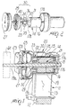
- FIG. 10 illustrates a permanent-magnet electric motor, which is generally designated by the reference numeral 10 and is of a per se known type already described in Italian patent application No. PD97A000124 filed June 12, 1997 in the name of the same Applicant.
- the electric motor 10 comprises a stator 11, a lamination pack 12 with windings 13, and a rotor 14 which is arranged between two poles 15 formed by the lamination pack 12.
- the rotor 14 is constituted by an annular cylindrical permanent magnet 16, on which a plastic element 17 is overmolded; the plastic element forms an internal tang 17a and end flanges 17b.
- the rotor 14 therefore is, as a whole, cylindrical with an axial hole 18 in which a shaft 19 is inserted; the rotor 14 can rotate freely about the shaft 19.
- the shaft 19 is in turn connected to a supporting structure, generally designated by the reference numeral 20, which in this case is composed of three complementary elements, designated by the reference numerals 21, 22 and 23 respectively, which are arranged coaxially and are joined by means of screws which are not illustrated.
- a supporting structure generally designated by the reference numeral 20, which in this case is composed of three complementary elements, designated by the reference numerals 21, 22 and 23 respectively, which are arranged coaxially and are joined by means of screws which are not illustrated.
- the supporting structure encloses the assembly constituted by the poles 15, the rotor 14 and the shaft 19, allowing the shaft in any case to protrude with an end 19a to which a working part to be turned is rigidly coupled.
- the working part is shown in dashed lines and designated by the reference numeral 24, and can be constituted for example by an impeller of a fan.
- the rotor 14 is arranged inside a hermetic housing, generally designated by the reference numeral 25, which is rigidly coupled to the shaft 19 and is composed of a cup-shaped element 26 and of a hermetic plug 27.
- the plug is arranged in a diametrically wider portion of the cup-shaped element 26 and is provided with vanes 28 which act as a turbine for a liquid which is contained in the hermetic housing 25 in which the rotor 14 is arranged.
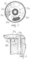
- the coupling 30 comprises at least one first driving tooth 31 and an internally hollow tang 32; both are monolithic with the corresponding flange 17b of the rotor 14 from which they protrude axially, and the tooth is eccentric (i.e., it is radially shifted with respect to the shaft 19 of the rotor 14).
- An annular element 33 made of an elastomer such as rubber is arranged so as to surround the tang 32 and one of its peripheral portions is adjacent to a radially internal portion of the first tooth 31.
- Two radial tabs designated by the reference numerals 34 and 35, respectively protrude from the annular element 33 and are arranged at the ends of the first tooth 31.
- At least one cantilevered element 36 protrudes from one of the radial tabs 34,35, in this case in particular the tab designated by the reference numeral 34, and is peripherally close to the cylindrical wall of the cup-shaped element 26, of which it partially follows the shape.
- the profile of the cantilevered element 36 has a circular portion 37, which is indeed adjacent to the wall of the cup-shaped element 26, and a straight portion 38, which gives it a wedge-like shape.
- the cantilevered element 36 forms, together with the annular element 33 with which it is monolithic, a hollow region 39 in which at least one second tooth 40 can partially enter.
- the second tooth 40 protrudes eccentrically with respect to the shaft 19 from the bladed impeller 29.
- the relative path, in one direction of rotation, between the second tooth 40 and the cantilevered element 36 causes the second tooth to radially push it outwards, flexing it against the cylindrical wall of the cup-shaped element 26 and blocking its motion.
- the second tooth 40 rests against the radial tab 35 and therefore interacts with the first tooth 31, making it rotate.
- the rotor 14 is disengaged from the load constituted by the bladed impeller 29 and can therefore start freely before rotationally driving the impeller.
- the impeller 29, together with the vanes 28, forms a viscous coupling in which the impeller provides kinetic energy to the working fluid contained in the housing 25 only in the direction in which the rotor 14 rotates.
- the kinetic energy is converted into pressure energy (head) by the shape of the vanes of the meridian ducts of the impeller 29.
- the working fluid moved in the vane ducts of the impeller 29 starts to circulate in the ducts of the vanes 28 of the plug 27, which accordingly start to rotate.
- the working part 24 is made to rotate.
- the viscous coupling combined with the driving coupling 30, ensures the direction-dependent start-up of the motor in conditions which are fully similar to those of an asynchronous motor.
- the element that provides direction-dependent motion (the annular element 33 with radial tabs 34 and 35 and a cantilevered element 36) is an independent part which is not integrated with the other parts of the coupling.
- a first effect of this is a simplification of the production mold, but in particular this allows to provide the element using the most adapted material in terms of mechanical characteristics and of impact cushioning in order to obtain low noise levels.
- the provision of the element that determines direction-dependent motion by using an elastomer such as rubber allows to utilize the high friction coefficient of the rubber to ensure initial quick and quiet blocking or allows to determine at will the degree of deformation of the cantilevered element 36 in a simple way by acting on the hardness of the material or on the geometry of the parts with no risk of jamming of the system, achieving adequate start-up responses.
- the radial tab 35 in the case of a correct direction of rotation at start-up, acts as a shock-absorber and therefore as a noise damping element.
- annular element 33 can be fitted equally with the radial tabs 34 and 35 on either side of the first tooth 31; this allows to decide the direction of rotation simply by changing the orientation with which it is assembled.
- the configuration of the load (for example the vane curvature of an impeller) must of course be adequate.
- the coupling has no articulated parts which may be easily subjected to jamming caused by the deposit of dirt.
- the first tooth now designated by the reference numeral 31a, covers an angle which is smaller than the angular space between the radial tabs, now designated by the reference numerals 34a and 35a, of the annular element, which is now designated by the reference numeral 33a.
- the annular element is provided, between the tabs 34a and 35a, with a tang 37a which has a semi-circular cross-section and is inserted in a complementarily shaped hollow 38a of the first tooth 31a, with which it makes contact.
- Friction can of course also be provided by simply acting on the interference between the annular element 33a and the tang arranged inside it, which is now designated by the reference numeral 32a.
- a permanent-magnet rotor 110 is arranged inside a tube-shaped chamber 111 (housing) which is arranged in the gap between two poles formed with a lamination pack 111a which are connected to windings (not shown), and can rotate freely with respect to a shaft 112 which is fixed axially to the chamber.
- the rotor 110 is composed of an annular permanent magnet 113 and of an overmolded element 114 made of plastics, which forms an internal tang 114a and end flanges 114b.
- a direction-dependent driving coupling according to the invention is arranged between the rotor 110 and the bladed impeller 115 which constitutes the working part.
- the impeller 115 which has a hub 117 fitted on an extension 118 of the internal tang 114a of the rotor 110, with respect to which it is in any case able to rotate freely, supports an annular element 119 which is rigidly coupled to the hub 117 and is of the same type as the preceding element 33.
- a first tooth 120 protrudes radially from the annular element 119 and in turn is rigidly (monolithically) provided with a cantilevered element 121, i.e., with an element which is peripherally close to the cylindrical wall of the tube-shaped chamber 111, of which it partially follows the shape and which has a substantially wedge-shaped free end.
- a hollow region 122 is formed between the cantilevered element 121 and the annular elastomeric element 119.
- annular element 119 As regards again the annular element 119, it is provided with grooves 123 which are complementary to grooves 124 of the hub 117 in order to rigidly rotationally couple it to the hub.
- the annular element 119 also is provided with axial hollows 125 which constitute seats for positioning raised portions 126 of the hub 117 in order to correctly position it and fix it axially.
- the driving coupling 116 also comprises a second tooth 127 which protrudes from a corresponding flange 114b of the overmolded element 114 of the rotor 110 and is arranged so that its path, in one direction, causes it to make contact with the first tooth 120, rotating it. In the opposite direction, the path of the second tooth causes it to make contact with the cantilevered element 121, partially entering the hollow region 122, causing a radial outward thrust which flexes it against the cylindrical wall of the chamber 111, blocking it.
- the cantilevered element 121 is rigidly coupled to the working part, differently from the preceding case, in which it was rigidly coupled to the rotor.
- this second embodiment also has shown the same advantages mentioned earlier for the first embodiment, except for the fact that in this case it is not possible to change, during assembly, the direction of rotation owing to the particular configuration of the coupling.
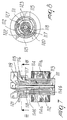
- a rotor 210 is composed of a permanent magnet 211 which has a cylindrical annular structure and on which a plastic element 212 is overmolded which forms an internal tang 212a and, at the ends, flanges 213.
- the rotor 210 has a cylindrical structure with an axial hole 214 in which a shaft 215 is inserted; the rotor 210 can rotate freely with respect to the shaft 215.
- the shaft 215 has a free end 215a which protrudes from the rotor 210 and with which a working part is rigidly associated, as will become apparent hereinafter.
- a direction-dependent driving coupling in this case in a third embodiment designated by the reference numeral 216 in the above figures, is interposed between the rotor 210 and the working part.
- the coupling 216 comprises a first driving tooth 217 which protrudes monolithically with respect to the flange 213 of the rotor 210 parallel to the shaft 215 in a radial eccentric position, i.e., shifted with respect to said shaft 215.
- a curved flap 218 protrudes monolithically from the flange 213 from a position which is rotated substantially through a right angle with respect to the first tooth 217; the flap is parallel to the shaft 215 and acts as an extension of the external structure of the rotor 210.
- a body 219 is overmolded on the shaft 215 proximate to the free end 215a, has a cylindrical structure and is axially crossed by the shaft 215.
- the body 219 has, on the side directed toward the rotor 210, an annular extension 220 which lies axially and has a smaller diameter and is also crossed with a rigid coupling by a corresponding portion of the shaft 215.
- a second tooth 221 protrudes from the body 219, is parallel to the annular extension 220 and is arranged eccentrically in a radial position, i.e., shifted with respect to the shaft 215 of the rotor 220.
- the external path covered by the second tooth 221 due to the rotation of the shaft 215 and of the body 219 that is rigidly coupled thereto does not interfere with the curved flap 218 which is rigidly coupled to the rotor 210.
- the driving coupling 216 comprises an annular element 222 made of an elastomer such as rubber which surrounds, on assembly, the extension 220 and has in particular a first radial tab 223 and a second radial tab 224 which are arranged at the ends of the second tooth 221.
- a cantilevered element 232 protrudes from the second radial tab 224 and is peripherally close to the cylindrical wall, schematically designated by the reference numeral 233, of a housing of the rotor 210.
- the overall shape of the second tab 224, produced by the cantilevered element 232 widens starting from the region proximate to the second tooth 221 until it interferes with the wall 233 of the housing.
- the free end 215a of the shaft 215 which is rigidly coupled to the working part, constituted for example by the bladed impeller of a fan not shown in the figures for the sake of simplicity, is supported by a cup-shaped element 226 on the bottom of which there is a hole which is crossed by the free end 215a.
- a thrust bearing 227 which absorbs the axial vibrations, and a sliding bearing, designated by the reference numeral 228 and of a per se known type, are arranged inside the cup-shaped supporting element 226.
- the direction of rotation is such as to bring the first driving tooth 217 to rest against the first radial tab 223, it also directly actuates the second tooth 221, which is in fact locked between the first radial tab 223 and the second radial tab 224, consequently rotating the body 219 as well and accordingly rotating the shaft 215 on which the working part is keyed.
- the curved flap 218 in fact is wedged, just before contact between the first tooth 217 and the first tab 223, between the second radial tab 224 and the cylindrical wall 223 of the housing, moving the cantilevered element 232 away from it so as to prevent contacts and consequent friction.
- first radial tab 223, pushed by the first tooth 217 rotates the second tooth 221 concordantly with it, it performs a shock-absorbing function, cushioning any impact and consequent noise.
- the materials used may be any according to the requirements.
Landscapes
- Engineering & Computer Science (AREA)
- General Engineering & Computer Science (AREA)
- Mechanical Engineering (AREA)
- Power Engineering (AREA)
- Structures Of Non-Positive Displacement Pumps (AREA)
- Permanent Magnet Type Synchronous Machine (AREA)
- Connection Of Motors, Electrical Generators, Mechanical Devices, And The Like (AREA)
- One-Way And Automatic Clutches, And Combinations Of Different Clutches (AREA)
- Dynamo-Electric Clutches, Dynamo-Electric Brakes (AREA)
- Synchronous Machinery (AREA)
- Iron Core Of Rotating Electric Machines (AREA)
Claims (16)
- Richtungsabhängige Antriebskupplung (30, 116, 216) zwischen dem Läufer (14, 110, 210) eines Synchronmotors mit Permanentmagneten und einer Arbeitspartie (24, 115) umfassend: wenigstens einen ersten exzentrischen Antriebszahn (31, 31a, 120, 217), der starr an ersterem, dem Läufer oder der Arbeitspartie (14, 210, 117), gekoppelt ist, zwischen denen Bewegung zu übertragen ist; einem Element (33, 119, 222), das richtungsabhängige Bewegung erlaubt, das wenigstens ein freitragendes Element (36, 121, 232) am Rand nahe der zylindrischen Wand angeordnet aufweist, deren Gestalt es teilweise folgt, wobei die Wand von einem Gehäuse (25, 111, 233) gebildet wird, in dem der Läufer (14, 110, 210) angeordnet ist, wobei das Gehäuse (25, 111, 233) beim Anfahren hinsichtlich der motorisierten Komponenten (14, 110, 210) bewegungslos ist; und wenigstens einen zweiten exzentrischen Zahn (40, 127, 221), der starr am zweiten, dem Läufer oder der Arbeitspartie (29, 110, 219), zwischen denen Bewegung zu übertragen ist, in einer solchen Position gekoppelt ist, dass der Lauf zwischen dem Läufer (14, 110, 210) und der Arbeitspartie (24, 115) den zweiten Zahn (40, 127, 210) veranlasst, in einer ersten Drehrichtung mit dem ersten Zahn (31, 31a, 120, 217) zusammenzuwirken und in einer zweiten, entgegengesetzten Drehrichtung mit dem freitragenden Element (36, 121, 232) zusammenzuwirken, einen radialen Schub nach Außen erzeugend, der das freitragende Element gegen die zylindrische Wand biegt, es dadurch blockierend, dadurch gekennzeichnet, dass das Element (33, 119, 222), das eine richtungsabhängige Bewegung erlaubt, wenigstens ein freitragendes Element (36, 121, 232) aufweist, als eine separate Komponente zwischen dem Läufer und der Arbeitspartie (14, 210, 117) vorgesehen ist und aus einem elastomeren Material gefertigt ist.
- Kupplung nach Anspruch 1, dadurch gekennzeichnet, dass sie ein freitragendes Element (36) umfasst, das von einem ringförmigen Element (33) absteht, welches das Element aufbaut, das die richtungsabhängige Bewegung erlaubt, welches zur Bewegungsübertragung an den ersten Zahn (31) gekoppelt ist.
- Kupplung nach Anspruch 2, dadurch gekennzeichnet, dass das ringförmige Element (33) radial innen hinsichtlich dem ersten exzentrischen Zahn (31) angeordnet ist und zwei Mitnehmer (34, 35) besitzt, die an dessen beiden Seiten angeordnet sind, wobei das freitragende Element (36) monolithisch mit einem (34) der Mitnehmer ist und davon absteht.
- Kupplung nach Anspruch 1, wobei das freitragende Element (36), bei Drehung in der zweiten Drehrichtung, mit einem seiner Abschnitte (37, 38) zwischen dem zweiten Zahn (40) und der Wand liegend angeordnet ist.
- Kupplung nach Anspruch 1, dadurch gekennzeichnet, dass der erste Zahn (31) starr an den Läufer (14) des Motors gekoppelt ist und dass das freitragende Element (36) zur Bewegungsübertragung an den ersten Zahn (31) gekoppelt ist, wobei die zylindrische Wand starr an die Arbeitspartie (24) gekoppelt ist.
- Kupplung nach Anspruch 5, dadurch gekennzeichnet, dass der zweite Zahn (40) monolithisch an ein geflügeltes Schaufelrad (29) gekoppelt ist, das als Pumpe wirkt und einem geflügelten Schaufelrad (27, 28) gegenüber liegt, das als Turbine wirkt und starr an die Wand gekoppelt ist, da es zusammen mit der Wand Teil eines drehbaren hermetischen Gehäuses (25) ist, in dem der Läufer (14) angeordnet ist.
- Kupplung nach Anspruch 1, dadurch gekennzeichnet, dass das freitragende Element (121) monolithisch mit dem ersten Zahn (120) ist.
- Kupplung nach Anspruch 7, dadurch gekennzeichnet, dass der erste Zahn (120) starr an die Arbeitspartie (115) gekoppelt ist und der zweite Zahn (127) starr an den Läufer (110) gekoppelt ist.
- Kupplung nach Anspruch 8, dadurch gekennzeichnet, dass die Arbeitspartie (115) eine Nabe (117) aufweist, die ein ringförmiges elastomeres Element (119) trägt, von dem der erste Zahn (120) radial absteht, das ringförmige Element (119) das freitragende Element (121) trägt, das starr daran gekoppelt ist und am Rand nahe der zylindrischen Wand einer röhrenförmigen Kammer (111) liegt, in welcher der Läufer (110) plaziert ist und die Teil der Trägerstruktur des Läufers (110) ist.
- Kupplung nach Anspruch 9, dadurch gekennzeichnet, dass der zweite Zahn (127) monolithisch mit dem Läufer (120) ist.
- Kupplung nach Anspruch 9, dadurch gekennzeichnet, dass das ringförmige Element innen mit Einkerbungen (123) versehen ist, die komplementär zu Einkerbungen (124) der Nabe (117) gestaltet sind, die angepasst sind, um das ringförmige Element (119) starr an die Nabe (117) für eine aneinander stoßende Drehung zu koppeln, das ringförmige Element (119) auch mit axialen Aushöhlungen (125) versehen ist, die Sitze zum Positionieren erhabener Abschnitte (126) der Nabe (117) zum korrekten Positionieren und axialen Fixieren aufbauen.
- Kupplung nach Anspruch 1, dadurch gekennzeichnet, dass wenigstens das freie Ende des freitragenden Elements (36, 121) im Wesentlichen keilförmig ist.
- Kupplung nach Anspruch 1, dadurch gekennzeichnet, dass zwischen dem ringförmigen elastomeren Element (33a) und der einen (14, 31a) der zwei Komponenten, die beim Anlaufen miteinander in einer Relativbewegung sein können, an der Seite, die der korrekten Drehrichtung entspricht, Teile (37a, 38a) vorhanden sind, die über einem vorgegebenen Winkel in Gleitkontakt stehen, um so eine Reibungswirkung zu liefern, um den Anlaufaufprall zu dämpfen.
- Kupplung nach Anspruch 13, dadurch gekennzeichnet, dass der Winkel, der vom ersten Zahn (31a) abgedeckt wird, kleiner ist, als der winkelige Raum zwischen den Mitnehmern (34a, 35a), die von dem ringförmigen Element (33a) abstehen, um so eine reibungsgesteuerte Relativbewegung beim Anlaufen zu liefern.
- Kupplung nach Anspruch 1, dadurch gekennzeichnet, dass der erste Zahn (217) starr an den Läufer (210) des Motors gekoppelt ist und der zweite Zahn (221) an die Arbeitspartie gekoppelt ist, eine gebogene Lasche (218) vom Läufer (210) absteht, an den sie starr gekoppelt ist, von einer Position, die hinsichtlich des ersten Zahns (217) gedreht ist, die Lasche (218) eine Verlängerung der äußeren Struktur des Läufers (210) bildet und sich selbst zwischen dem freitragenden Element (232) und der zylindrischen Wand (233) einkeilt, wenn der erste Zahn (217) den zweiten Zahn (221) antreibt, der an die Arbeitspartie gekoppelt ist, um so jeden Kontakt zu verhindern, die zylindrische Wand (233) hinsichtlich der motorisierten Komponente (210) fixiert wird.
- Kupplung nach Anspruch 6, dadurch gekennzeichnet, dass das Gehäuse (25), in dem der Läufer (14) angeordnet ist, in Hinblick auf den Ständer (11) fixiert ist.
Applications Claiming Priority (3)
| Application Number | Priority Date | Filing Date | Title |
|---|---|---|---|
| ITPD980003 | 1998-01-08 | ||
| IT98PD000003A ITPD980003A1 (it) | 1998-01-08 | 1998-01-08 | Giunto di trascinamento monodirezionale fra il rotore di un motore sincrono a magneti permanenti e l'organo operatore |
| PCT/EP1998/008518 WO1999035403A1 (en) | 1998-01-08 | 1998-12-30 | Direction-dependent driving coupling between the rotor of a permanent-magnet synchronous motor and the working part |
Publications (2)
| Publication Number | Publication Date |
|---|---|
| EP0966612A1 EP0966612A1 (de) | 1999-12-29 |
| EP0966612B1 true EP0966612B1 (de) | 2003-07-23 |
Family
ID=11392004
Family Applications (1)
| Application Number | Title | Priority Date | Filing Date |
|---|---|---|---|
| EP98965291A Expired - Lifetime EP0966612B1 (de) | 1998-01-08 | 1998-12-30 | Richtungsabhängige antriebskupplung zwischen dem rotor eines permanent-magnetischen synchronmotors und der last |
Country Status (7)
| Country | Link |
|---|---|
| US (1) | US6217452B1 (de) |
| EP (1) | EP0966612B1 (de) |
| AT (1) | ATE245770T1 (de) |
| AU (1) | AU2054999A (de) |
| DE (1) | DE69816597T2 (de) |
| IT (1) | ITPD980003A1 (de) |
| WO (1) | WO1999035403A1 (de) |
Families Citing this family (12)
| Publication number | Priority date | Publication date | Assignee | Title |
|---|---|---|---|---|
| ITPD980058A1 (it) * | 1998-03-19 | 1999-09-19 | Askoll Holding Srl | Dispositivo di trascinamento, con angolo di libera rotazione ampliato fra il motore sincrono a magneti permanenti e l'organo operatore |
| US6478555B1 (en) * | 1999-06-16 | 2002-11-12 | Lg Electronics, Inc. | Apparatus for controlling noise and vibration for drain pump |
| GB2353330B (en) * | 1999-08-04 | 2003-05-28 | Pet Mate Ltd | Pond pump |
| EP1365157B1 (de) * | 2000-07-06 | 2006-12-13 | Askoll Holding S.r.l. | Unidirektionales Laufrad für eine elektrische Kreiselpumpe mit einem Permanentmagnet Synchronmotor |
| CA2450459A1 (en) * | 2001-06-13 | 2002-12-19 | Tri-Tech, Inc. | Linear valve actuator |
| EP1357297B1 (de) * | 2002-04-24 | 2011-07-20 | Grundfos A/S | Elektromotorisch angetriebenes Kreiselpumpenaggregat |
| ES2268240T3 (es) | 2002-09-03 | 2007-03-16 | Emerson Appliance Motors Europe S.R.L. | Bomba centrifuga para aparatos electrodomesticos. |
| CN100465455C (zh) * | 2003-11-26 | 2009-03-04 | 普拉塞特股份有限公司 | 尤其用于家用电器中的离心泵 |
| EP1553681B1 (de) * | 2003-12-31 | 2017-03-15 | Askoll Holding S.r.l. | Kupplungsvorrichtung zwischen einem Rotor eines Permanentmagnetsynchronmotors und einem Funktionsteil |
| DE102004056508B3 (de) * | 2004-11-24 | 2006-03-09 | Hanning Elektro-Werke Gmbh & Co. Kg | Synchronmotor mit Anlaufeinrichtung |
| CN2916195Y (zh) * | 2006-01-26 | 2007-06-27 | 江门市汉宇电器有限公司 | 一种离心式排水泵 |
| ATE487415T1 (de) * | 2007-09-27 | 2010-11-15 | Electrolux Home Prod Corp | Rotationspumpe, insbesondere für geschirrspülmaschinen oder waschmaschinen |
Family Cites Families (10)
| Publication number | Priority date | Publication date | Assignee | Title |
|---|---|---|---|---|
| US770641A (en) * | 1904-09-20 | Clutch | ||
| GB361656A (en) * | 1930-12-13 | 1931-11-26 | Austin John Morgan Jones | An improved brake for preventing reverse motion |
| US1968771A (en) * | 1933-04-03 | 1934-07-31 | William A Jex | One-way clutch |
| US2224935A (en) * | 1939-02-02 | 1940-12-17 | William F Schultz | Starting motor drive |
| DE1230531B (de) * | 1965-04-10 | 1966-12-15 | Dornier System Gmbh | Bremseinrichtung fuer Seilschleppwinden, insbesondere in Luftziel-Schleppsystemen |
| US3581857A (en) * | 1969-09-24 | 1971-06-01 | North American Clutch Corp | One-way centrifugal clutch |
| DE3345323A1 (de) * | 1983-12-15 | 1985-06-27 | Gunther Eheim Fabrik Elektromechanischer Erzeugnisse, 7301 Deizisau | Motorpumpenaggregat |
| ES8705090A1 (es) | 1985-07-01 | 1987-04-16 | Easthorpe Investments Ltd | Bomba centrifuga,en particular para lavadoras, lavaplatos y aparatos domesticos similares. |
| US4803855A (en) * | 1987-08-10 | 1989-02-14 | Whirlpool Corporation | Single shaft agitate and spin drive for automatic washer |
| JPH07158663A (ja) * | 1993-12-07 | 1995-06-20 | Nikon Corp | 一方向クラッチ |
-
1998
- 1998-01-08 IT IT98PD000003A patent/ITPD980003A1/it unknown
- 1998-12-30 DE DE69816597T patent/DE69816597T2/de not_active Expired - Lifetime
- 1998-12-30 AU AU20549/99A patent/AU2054999A/en not_active Abandoned
- 1998-12-30 WO PCT/EP1998/008518 patent/WO1999035403A1/en active IP Right Grant
- 1998-12-30 US US09/380,568 patent/US6217452B1/en not_active Expired - Lifetime
- 1998-12-30 AT AT98965291T patent/ATE245770T1/de not_active IP Right Cessation
- 1998-12-30 EP EP98965291A patent/EP0966612B1/de not_active Expired - Lifetime
Also Published As
| Publication number | Publication date |
|---|---|
| DE69816597T2 (de) | 2004-04-08 |
| ATE245770T1 (de) | 2003-08-15 |
| WO1999035403A1 (en) | 1999-07-15 |
| ITPD980003A1 (it) | 1999-07-08 |
| DE69816597D1 (de) | 2003-08-28 |
| ITPD980003A0 (it) | 1998-01-08 |
| AU2054999A (en) | 1999-07-26 |
| EP0966612A1 (de) | 1999-12-29 |
| US6217452B1 (en) | 2001-04-17 |
Similar Documents
| Publication | Publication Date | Title |
|---|---|---|
| US7097434B2 (en) | Device for transmitting motion between the rotor of a synchronous permanent-magnet motor and the working part, having an increased free rotation angle | |
| EP0966612B1 (de) | Richtungsabhängige antriebskupplung zwischen dem rotor eines permanent-magnetischen synchronmotors und der last | |
| EP1908959B1 (de) | Pumpenrad-Kupplungsvorrichtung mit eingeschränkter freier Bewegung | |
| EP1365157B1 (de) | Unidirektionales Laufrad für eine elektrische Kreiselpumpe mit einem Permanentmagnet Synchronmotor | |
| US5668425A (en) | Startup device for the rotor of a permanent-magnet synchronous motor | |
| JP2008524975A (ja) | 回転と軸方向運動のための電動機 | |
| EP3135921B1 (de) | Flüssigkeitspumpe, motor und wellenbuchseneinheit dafür | |
| CN110873061A (zh) | 泵体及用于泵体的转子组件的制造方法 | |
| GB2425156A (en) | Bearing arrangement for an electric motor | |
| US20080219875A1 (en) | Magnetic drive vane pump | |
| US6478555B1 (en) | Apparatus for controlling noise and vibration for drain pump | |
| US6335579B1 (en) | Electric motor with permanent-magnet rotor having viscous shaft coupling | |
| EP0945622B1 (de) | Synchronmotorpumpe mit Schalldämpfereinrichtung | |
| US20170271968A1 (en) | Electric motor and electric apparatus using same | |
| KR20040089337A (ko) | 브러시리스 모터용 회전자 및 이의 제조방법 | |
| EP3926172B1 (de) | Motor, pumpe und waschvorrichtung | |
| JP4850665B2 (ja) | 流体ポンプ装置 |
Legal Events
| Date | Code | Title | Description |
|---|---|---|---|
| PUAI | Public reference made under article 153(3) epc to a published international application that has entered the european phase |
Free format text: ORIGINAL CODE: 0009012 |
|
| AK | Designated contracting states |
Kind code of ref document: A1 Designated state(s): AT CH DE DK ES FR GB IT LI NL SE |
|
| 17P | Request for examination filed |
Effective date: 19991223 |
|
| 17Q | First examination report despatched |
Effective date: 20020409 |
|
| GRAH | Despatch of communication of intention to grant a patent |
Free format text: ORIGINAL CODE: EPIDOS IGRA |
|
| GRAH | Despatch of communication of intention to grant a patent |
Free format text: ORIGINAL CODE: EPIDOS IGRA |
|
| GRAA | (expected) grant |
Free format text: ORIGINAL CODE: 0009210 |
|
| AK | Designated contracting states |
Designated state(s): AT CH DE DK ES FR GB IT LI NL SE |
|
| PG25 | Lapsed in a contracting state [announced via postgrant information from national office to epo] |
Ref country code: NL Free format text: LAPSE BECAUSE OF FAILURE TO SUBMIT A TRANSLATION OF THE DESCRIPTION OR TO PAY THE FEE WITHIN THE PRESCRIBED TIME-LIMIT Effective date: 20030723 Ref country code: LI Free format text: LAPSE BECAUSE OF FAILURE TO SUBMIT A TRANSLATION OF THE DESCRIPTION OR TO PAY THE FEE WITHIN THE PRESCRIBED TIME-LIMIT Effective date: 20030723 Ref country code: CH Free format text: LAPSE BECAUSE OF FAILURE TO SUBMIT A TRANSLATION OF THE DESCRIPTION OR TO PAY THE FEE WITHIN THE PRESCRIBED TIME-LIMIT Effective date: 20030723 Ref country code: AT Free format text: LAPSE BECAUSE OF FAILURE TO SUBMIT A TRANSLATION OF THE DESCRIPTION OR TO PAY THE FEE WITHIN THE PRESCRIBED TIME-LIMIT Effective date: 20030723 |
|
| REG | Reference to a national code |
Ref country code: GB Ref legal event code: FG4D |
|
| REG | Reference to a national code |
Ref country code: CH Ref legal event code: EP |
|
| REF | Corresponds to: |
Ref document number: 69816597 Country of ref document: DE Date of ref document: 20030828 Kind code of ref document: P |
|
| PG25 | Lapsed in a contracting state [announced via postgrant information from national office to epo] |
Ref country code: SE Free format text: LAPSE BECAUSE OF FAILURE TO SUBMIT A TRANSLATION OF THE DESCRIPTION OR TO PAY THE FEE WITHIN THE PRESCRIBED TIME-LIMIT Effective date: 20031023 Ref country code: DK Free format text: LAPSE BECAUSE OF FAILURE TO SUBMIT A TRANSLATION OF THE DESCRIPTION OR TO PAY THE FEE WITHIN THE PRESCRIBED TIME-LIMIT Effective date: 20031023 |
|
| PG25 | Lapsed in a contracting state [announced via postgrant information from national office to epo] |
Ref country code: ES Free format text: LAPSE BECAUSE OF FAILURE TO SUBMIT A TRANSLATION OF THE DESCRIPTION OR TO PAY THE FEE WITHIN THE PRESCRIBED TIME-LIMIT Effective date: 20031103 |
|
| NLV1 | Nl: lapsed or annulled due to failure to fulfill the requirements of art. 29p and 29m of the patents act | ||
| REG | Reference to a national code |
Ref country code: CH Ref legal event code: PL |
|
| ET | Fr: translation filed | ||
| PLBE | No opposition filed within time limit |
Free format text: ORIGINAL CODE: 0009261 |
|
| STAA | Information on the status of an ep patent application or granted ep patent |
Free format text: STATUS: NO OPPOSITION FILED WITHIN TIME LIMIT |
|
| 26N | No opposition filed |
Effective date: 20040426 |
|
| REG | Reference to a national code |
Ref country code: FR Ref legal event code: PLFP Year of fee payment: 18 |
|
| REG | Reference to a national code |
Ref country code: FR Ref legal event code: PLFP Year of fee payment: 19 |
|
| REG | Reference to a national code |
Ref country code: FR Ref legal event code: PLFP Year of fee payment: 20 |
|
| PGFP | Annual fee paid to national office [announced via postgrant information from national office to epo] |
Ref country code: DE Payment date: 20171120 Year of fee payment: 20 Ref country code: FR Payment date: 20171121 Year of fee payment: 20 |
|
| PGFP | Annual fee paid to national office [announced via postgrant information from national office to epo] |
Ref country code: GB Payment date: 20171121 Year of fee payment: 20 Ref country code: IT Payment date: 20171120 Year of fee payment: 20 |
|
| REG | Reference to a national code |
Ref country code: DE Ref legal event code: R071 Ref document number: 69816597 Country of ref document: DE |
|
| REG | Reference to a national code |
Ref country code: GB Ref legal event code: PE20 Expiry date: 20181229 |
|
| PG25 | Lapsed in a contracting state [announced via postgrant information from national office to epo] |
Ref country code: GB Free format text: LAPSE BECAUSE OF EXPIRATION OF PROTECTION Effective date: 20181229 |