EP0965794B1 - Support plate - Google Patents
Support plate Download PDFInfo
- Publication number
- EP0965794B1 EP0965794B1 EP99111499A EP99111499A EP0965794B1 EP 0965794 B1 EP0965794 B1 EP 0965794B1 EP 99111499 A EP99111499 A EP 99111499A EP 99111499 A EP99111499 A EP 99111499A EP 0965794 B1 EP0965794 B1 EP 0965794B1
- Authority
- EP
- European Patent Office
- Prior art keywords
- support plate
- film
- bottom face
- plate
- layers
- Prior art date
- Legal status (The legal status is an assumption and is not a legal conclusion. Google has not performed a legal analysis and makes no representation as to the accuracy of the status listed.)
- Expired - Lifetime
Links
Images

Classifications
-
- F—MECHANICAL ENGINEERING; LIGHTING; HEATING; WEAPONS; BLASTING
- F24—HEATING; RANGES; VENTILATING
- F24B—DOMESTIC STOVES OR RANGES FOR SOLID FUELS; IMPLEMENTS FOR USE IN CONNECTION WITH STOVES OR RANGES
- F24B13/00—Details solely applicable to stoves or ranges burning solid fuels
- F24B13/002—Surrounds
Definitions
- the invention relates to a support plate, in particular for ovens, e.g. Stoves, according to the Preamble of claim 1.
- a support plate of the generic type is e.g. known from DE 92 03 789 U1.
- the one in it described protection device for fireplaces in buildings is made of a safety glass plate with an increased thermal shock resistance, bending strength, impact and Impact resistance is formed and can be arranged in front of or below the hearth.
- This Safety glass plate should be visually appealing compared to stone slabs and the respective floor or floor covering of the installation site of the safety glass panel before sparks protect from the hearth.
- the disadvantage of this glass plate is that it unevenness the underlying soil or floor covering can not be compensated and thus the underside of the glass plate over the period of use of the oven standing thereon increasingly polluted.
- thermo-plate for ovens is known, both in the field of Rear wall as well as in the area of the floor can be arranged, so on the one hand the Protect the rear wall or the floor from direct heat exposure through the stove and on the other hand, to increase the efficiency of the furnace, as this is to prevent Heat is lost through heat conduction through the wall or the floor.
- This thermo shield consists of a non-asbestos insulating material, which is in the range of the furnace facing surfaces is covered by a metal sheet. About spacers is a reaches spaced support to the wall, so that the cherrieskonvetation is made possible.
- This thermowell is made by profile elements, which are arranged on the outer periphery, Held on the wall.
- the object of the invention is to develop a support plate, in particular for ovens in such a way that the support plate during the time of their use their own optical properties then retains, if it is only cleaned in the easily accessible places.
- Another advantage is a development according to claim 2, since thus the protection of the soil can be improved.
- An embodiment variant according to claim 6, according to which it is possible, is also advantageous adapt the support plate different load cases or the optical design to vary the support plate.
- Another advantage is also a development according to claims 7 to 9, since it makes it possible is to arrange the material so that it does not look when viewed from above through the support plate can be viewed and can thus improve the visual appearance of the support plate become.
- An advantage of the embodiment according to claim 11 is that by the multilayer structure a recess for the material to be recorded can be produced by simple means can.
- the arrangement of at least one film between two layers according to claim 12 allows On the one hand, to make the visual appearance of the support plate arbitrary and can be achieved on the other hand, that in case of accidental destruction of the support plate, this does not disintegrate into pieces.
- the support plate is given a visually appealing, very individual look and is it on the other hand with it possible to cover the material.
- an embodiment according to claim 23 is advantageous because so a simple cover of the material can be achieved and also sharp edges of the Support plate can be avoided.
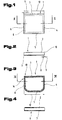
- Figs. 1 and 2 show a support plate 1 in a schematically simplified representation.
- Such support plates 1 may be used, for example, for ovens, e.g. Stoves or the like, be used as a protective device for floors when the support plate 1 between the oven and the floor is arranged. It is thus possible to use floors, e.g. Flooring made of plastic, wooden floors or the like, in front of the hearth of a furnace falling down To protect embers or sparks. Of course it is also possible to use this support plate 1 as footprint for other arbitrary body.
- the support plate 1 comprises a top 2, a bottom 3 and arranged therebetween Side surfaces 4 to 7, wherein depending on the outer shape of the support plate 1 only individual of these side surfaces 4 to 7 may be arranged. For example, show circular support plates 1 only one side surface 3.
- the support plate 1 any outer shape, so for example square, rectangular, oval, round or the like., Have.
- the support plate 1 can at least partially by an inorganic melt product, For example, be formed glass, especially safety glass.
- the support plate 1 may have a multilayer structure, wherein at least one Layer should be formed from the inorganic melt product.
- a material 8 in particular be fixed on the underside 3 of the support plate 1, a material 8, in particular be fixed. This material 8 is at a distance 9 arranged from the outer side edges 10 of the support plate 1.
- the material 8 is to be able to compensate for bumps, a modulus of elasticity which is less than the elastic modulus of the inorganic Melting product.
- the material 8 may, for example, in particular liquid and be formed dust-impermeable seal and the shape of a sealing cord, a sealing profile of any shape or the like.
- a material for the material 8 e.g. an elastically deformable polymer material, silicone, Rubber, sponge rubber or the like. Be used.
- the material 8 is within a width 11 on the underside 3 of the support plate 1 arranged.
- the width 11 is only a fraction of the total width 12 of Support plate 1.
- the arrangement of the material 8 can be achieved that uneven floors and thus compensated height differences between the bottom and the support plate 1 can be prevented, so that it can be prevented in the episode that dirt, dust, Moisture, water or the like.
- the optical quality that is, the appearance of the support plate 1 constantly deteriorates over the period of use, whereby the support plate 1 is unsightly over time.
- a cleaning the support plate 1, in particular in the region of the bottom 3, is due to the usual on the top 2 standing heavy body, such as the stoves, difficult or not possible, since in particular such stoves only below crazy and can be lowered from the top 2 or in this case is also the release of the connection to a flue-gas extraction device, For example, a chimney necessary and thus with an increased dust load, for example, by soot particles to be expected.
- a protective device for fire pits as described in the aforementioned DE 92 03 789 U1 is known, but can not meet these requirements, as this protection device consists of a rigid safety glass plate which is unable to naturally compensate for existing bumps.
- the material 8 in addition to the arrangement of the material 8 in the region of the bottom 3 and the side surfaces 4 to 7 but it is of course possible that, as in a later embodiment is shown, the material 8 additionally arranged on the top 2 is, especially in the areas near the side surfaces 4 to 7.
- FIG. 3 and 4 an embodiment of the support plate 1 in plan view and in Front view cut in accordance with the line IV - IV in Fig. 3 schematically simplified shown.
- the support plate 1 in this case has a shape which is rectilinear extending side surface 7 and a round side surface 5, which now the two other side surfaces 6 and 7, characterized. This should be the possibility the diversity of the support plate 1 are shown.
- This embodiment of the support plate 1 in turn has on the bottom 3 the Material 8 on.
- surface configurations 14 be arranged on the upper side 2, in the area 13, surface configurations 14 be arranged.
- the width of the region 13 can only a part of the total width 12 of the support plate 1 include.
- the width of the region 13 extends over the total width 12 and thus the surface configurations 14 are arranged over the entire surface of the upper side 2.
- the surface designs 14 attached to the side surfaces 4 to 7 and / or the bottom 3 are.
- the surface designs 14 may be, for example, by means of a printing process getting produced. It is also possible, of course, the surface designs 14 as a foil or film parts and perform this on the appropriate pages, in particular the top 2 and / or the bottom 3 and / or the side surfaces 4 bis 7 attach, for example, stick. But it can also be one in the inorganic Melt product einbrennbare film can be used, so that a good bond between the films or the film parts and the inorganic melt product can be.
- Another possibility is to use both the film and the printing process next to each other for the support plate 1 to use, so that both a printed image on at least one of the surfaces of the support plate 1 as well as one at least partially arranged film is present.
- the support plate 1 makes it possible on the one hand, the support plate 1 to give a visually appealing appearance and on the other hand is It thus possible to arrange the material 8 on the support plate 1, that it normally can not be seen through a view from above on the support plate 1 can.
- the material 8 can be, for example, along the dot-dash line in FIG Line be arranged within the area 13 at the bottom 3, so that it through the surface designs 14 at least partially, preferably completely, is covered.
- such materials can be used for the material 8 which do not have any special aesthetic shapes or colors or the like.
- the surface designs 14 may be of any shape. For example These can be used as points, stripes, flat entities of any size or Embodiment or the like. Be formed. It can be used as any design Patterns are designed.
- the surface features 14 may be any color and may be For example, mixed dyeings are used.
- FIG. 5 and 6 show a further embodiment of the support plate 1, which in this example is designed as a round disc.
- this support plate 1 or all conceivable embodiments of the support plate 1 no sharp-edged side edges 10, but rather rounded side edges 10 have.
- the visual appearance of the support plate 1 is additionally changed and thus can also prevent possible injury from sharp edges become.
- the bottom 3 and / or the top 2 and / or the side surfaces 4 to 7 - this particular embodiment naturally has only one side surface 4 - at least partially frosted, for example by sandblasting, Etching, e.g. with hydrofluoric acid or the like.
- the matting can be different levels and can be designed so that the support plate 1 at least partially is opaque or opaque. It is thus a running, for example increasing matting possible.
- FIGs. 7 to 8 another embodiment of the support plate 1 is schematically shown in simplified form. This is to express that the surface designs 14 may have any shape and thus the support plate. 1 For example, a marble-like design or the like. Can be awarded.
- the surface configurations 14 on the Bottom 3 and be arranged in the bottom 3 so that they are at least partially between the material 8 and the inorganic melt product, so that the material 8 in turn can be withdrawn from consideration.
- the support plate is formed multi-layered, it goes without saying possible that the surface configurations 14 between the material 8 instead of the inorganic Melt product and arranged above, suitable layer of Support plate 1 are available.
- the material 8 can be mixed with the inorganic melt product, So for example, with the glass or the interposed surface designs 14 connected, in particular glued. Will for the training the surface designs 14 uses a film, it is possible to self-adhesive so that the film easily adheres to the inorganic melted product or a corresponding other layer of the support plate 1 can be attached. But it is also possible to offer the individual components separately or as a package, so that the user of the support plate 1 this according to his wishes can shape. In particular, it is also possible with multi-layer support plates 1, to offer the individual layers separately.
- the film is self-adhesive on both sides, it can be achieved that Also, the material 8 is easy to attach, so that the support plate without special Expense can be put together by laymen.
- Fig. 9 shows a variant of the support plate 1 is shown, in which the Material not only along the outer circumference, but additionally in an interior area 15, e.g. in the area of a footprint of a body to be worn attached is.
- This additional material 8 can according to the contour of the footprint a body to be worn or it is possible, as this is shown by the dashed lines in Fig. 9, additional material 8 also to install within these contours.
- this additional material 8 can be achieved be that, in particular, when the support plate 1 for heavy objects, such as This example, stoves are, is used, the support plate 1 in the field of Contact surface of the body to be supported is supported and thus a deflection the support plate 1 can be largely prevented in this area.
- To the additional material 8 is preferably arranged on the underside 3 of the support plate 1.
- any x-any design design design the support plate 1 with imprints or films or the like. Possible.
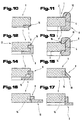
- FIGS. 10 to 17 show further possibilities in detail and schematically greatly simplified to attach the material 8 to or at least partially in the support plate 1, these possibilities by no means limit the invention but the invention also includes other conceivable embodiments.
- the material 8 may, for example, as shown in FIGS. 10, 12 to 17 in dash-dotted lines Representation shown, at least partially extend into a groove 16. This can be a secure bond, for example by gluing, between the material 8 and the overlying Layer of the support plate 1, for example, the inorganic melt product or the film or the imprint, and can be the material 8 are protected against lateral slippage.
- suitable Material choice for the material 8 is dispensed with an additional connection can be, for example, if the material of the polymer material with adhesive surface properties is formed.
- the arrangement of the groove 16 also allows that, especially if the support plate 1 is offered as a modular system, the support plate 1 easy and accurate fit can be put together by the buyer.
- the material 8 may be at least partially extend over all surfaces of the support plate 1, so both over a Part of the bottom 3, over the area of the side surfaces 4 to 7 and / or a Part of the top 2. Again, it is possible, as in Fig. 13 shows that at least one groove 16 in at least one layer of the support plate 1 is arranged.
- the material 8 Due to this design of the material 8 as a profile, which have any suitable shape can, on the one hand, on the other hand, it is possible, the material 8 of the exact fit or assign the layer (s) of the support plate 1 and can thus, in particular for the Case that the support plate 1 is made of a multi-layer, a secure cohesion of individual layers can be achieved. It is also possible, the side edges 10 to protect against accidental damage or may therefore the risk of injury be reduced by the side edges 10.
- the support plate can. 1 be formed multi-layered. At least one of the layers can be used as a glass plate, be designed as a plastic plate, as a ceramic plate or the like. Preferably is a top layer 17 made of a heat-resistant material, such as a Glass plate, formed.
- a film for example, a plastic film instead or in addition to arrange the surface configurations 14.
- this film or by area between the layers arranged film parts is an individual Design and adaptability of the support plate 1 to the body to be worn possible. For example, can slide parts of different colors between the layers to be ordered.
- the film is arranged only between two layers is or attached that between at least two layers imprints become.
- material 8 at least partially form so that it in a crooked Angle is inclined against the ground underneath or that a material underside 18 at least partially in the plane of the bottom 3 of the support plate. 1 is arranged.
- the inorganic melt product for example the glass plate
- the support plate 1 is made of a multi-layered is and between at least two layers a film is arranged, this film with Is provided recesses, so that a mixed color in different areas of the Support plate may arise, especially when using differently colored Layers.
- At least one of the layers or the entire support plate 1 has a increased thermal shock resistance, a corresponding bending strength or shock and impact resistance.
- the support plate 1 it is also possible that if a film is arranged between the layers, this is carried out so that in the event of damage or breakage of one of the layers of the support plate 1 the individual fragments, for example due to corresponding adhesive forces an adhesive layer, do not spread in the installation space of the support plate 1, but rather the support plate 1 held together substantially in shape becomes.
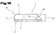
- Fig. 18 is a further embodiment of the support plate 1 according to the invention in shown schematically simplified representation. Based on this figure is the possibility are shown, at least one, preferably more of the side edges 10th be provided with a chamfer, for example, to grind (in Fig. 18 is the original Side edge 10 shown in dashed lines in the left part). Of course it is but also possible, this bevel already during the production of the single layer or layers, for example of the inorganic melt product, for the support plate 1, so that subsequent processing is no longer necessary is.
- the abrading or removal by means of suitable means of the side edge 10 offers the advantage that under certain circumstances a milky cloudy surface is created, so that thus arranged on the bottom 3 material 8 can be covered. It may therefore be an additional matting of this part of the support plate 1 under certain circumstances be waived or can be done supportive Matting.
- the chamfer may be over a total thickness 19 of the support plate 1 extend or, as shown in the left part of Fig. 18, only part of the total thickness 19 can be bevelled.
Abstract
Description
Die Erfindung betrifft eine Tragplatte, insbesondere für Öfen, z.B. Kaminöfen, gemäß dem
Oberbegriff des Anspruches 1.The invention relates to a support plate, in particular for ovens, e.g. Stoves, according to the
Preamble of
Eine Tragplatte der gattungsgemäßen Art ist z.B. aus der DE 92 03 789 U1 bekannt. Die darin beschriebene Schutzvorrichtung für Feuerstellen in Gebäuden ist aus einer Sicherheitsglasplatte mit einer erhöhten Temperaturwechselbeständigkeit, Biegebruch-festigkeit, Schlagund Stoßfestigkeit ausgebildet und kann vor oder unter der Feuerstelle angeordnet sein. Diese Sicherheitsglasplatte soll im Vergleich zu Steinplatten optisch ansprechender sein und den jeweiligen Boden bzw. Bodenbelag des Aufstellungsortes der Sicherheitsglasplatte vor Funken aus der Feuerstelle schützen. Nachteilig bei dieser Glasplatte ist, daß damit Unebenheiten des darunter angeordneten Bodens bzw. Bodenbelages nicht ausgeglichen werden können und somit die Unterseite der Glasplatte über die Verwendungsdauer des darauf stehenden Ofens immer stärker verschmutzt.A support plate of the generic type is e.g. known from DE 92 03 789 U1. The one in it described protection device for fireplaces in buildings is made of a safety glass plate with an increased thermal shock resistance, bending strength, impact and Impact resistance is formed and can be arranged in front of or below the hearth. This Safety glass plate should be visually appealing compared to stone slabs and the respective floor or floor covering of the installation site of the safety glass panel before sparks protect from the hearth. The disadvantage of this glass plate is that it unevenness the underlying soil or floor covering can not be compensated and thus the underside of the glass plate over the period of use of the oven standing thereon increasingly polluted.
Aus der US 4,416,251 A ist ein Thermoschild für Öfen bekannt, der sowohl im Bereich der Rückwand als auch im Bereich des Bodens angeordnet werden kann, um damit einerseits die Rückwand bzw. den Boden vor der direkten Hitzeeinwirkung durch den Ofen zu schützen und um andererseits die Effizienz des Ofens zu steigern, da damit verhindert werden soll, daß Wärme durch Wärmeleitung durch die Wand bzw. den Boden verloren geht. Dieser Thermoschild besteht aus einem nicht asbestösen Dämmmaterial, welches im Bereich der dem Ofen zugewandten Oberflächen durch ein Metallblech abgedeckt ist. Über Abstandshalter wird eine beabstandete Halterung zur Wand erreicht, sodaß die Wärmekonvektion ermöglicht wird. Dieser Thermoschild wird über Profilelemente, welche am äußeren Umfang angeordnet sind, an der Wand gehaltert.From US 4,416,251 A, a thermo-plate for ovens is known, both in the field of Rear wall as well as in the area of the floor can be arranged, so on the one hand the Protect the rear wall or the floor from direct heat exposure through the stove and on the other hand, to increase the efficiency of the furnace, as this is to prevent Heat is lost through heat conduction through the wall or the floor. This thermo shield consists of a non-asbestos insulating material, which is in the range of the furnace facing surfaces is covered by a metal sheet. About spacers is a reaches spaced support to the wall, so that the Wärmekonvektion is made possible. This thermowell is made by profile elements, which are arranged on the outer periphery, Held on the wall.
Aufgabe der Erfindung ist es, eine Tragplatte, insbesondere für Öfen derart weiterzubilden, daß die Tragplatte während der Zeit ihrer Verwendung ihre optischen Eigenschaften selbst dann beibehält, wenn diese nur an den leicht zugänglichen Stellen gereinigt wird.The object of the invention is to develop a support plate, in particular for ovens in such a way that the support plate during the time of their use their own optical properties then retains, if it is only cleaned in the easily accessible places.
Diese Aufgabe wird durch die Merkmale im Kennzeichenteil des Anspruches 1 gelöst. Vorteilhaft
ist dabei, daß durch die Anordnung eines Materials im Bereich der Seitenflächen
und/oder der Unterseite, dessen Elastizitätsmodul geringer ist, als der des anorganischen
Schmelzproduktes, Bodenunregelmäßigkeiten ausgeglichen werden können, sodaß der Raum
zwischen der Tragplatte und dem darunter angeordneten Boden im wesentlichen vor z.B.
Staub, Schmutz, Feuchtigkeit, wie z.B. Wasser oder Putzlösungen, geschützt ist. Damit kann
ein Eindringen dieser Substanzen in den Raum unterhalb der Glasplatte verhindert werden
und wird aufgrund dessen das optisch ansprechende Aussehen der Tragplatte nicht beeinträchtigt.This object is achieved by the features in the characterizing part of
Von Vorteil ist auch eine Weiterbildung nach Anspruch 2, da damit der Schutz des Bodens
verbessert werden kann.Another advantage is a development according to
Durch die Anordnung des Materials im Bereich des gesamten Umfanges der Tragplatte, wie
im Anspruch 3 beschrieben, kann eine bessere Lastabtragung auf den darunterliegenden Boden
erreicht werden.Due to the arrangement of the material in the area of the entire circumference of the support plate, such as
described in
Vorteilhaft ist aber auch eine Ausbildung nach Anspruch 4, wonach das Material im Bereich einer Aufstandsfläche eines zu tragenden Körpers angeordnet ist. Damit ist es einerseits möglich, dieses zusätzlich angeordnete Material durch den darüber angeordneten Körper zu verdecken und kann eine Durchbiegung der Tragplatte aufgrund des darauf lastenden Gewichts des zu tragenden Körpers weitgehend verhindert werden.But also advantageous is an embodiment according to claim 4, according to which the material in the field a footprint of a body to be worn is arranged. On the one hand, this makes it possible to cover this additionally arranged material by the overlying body and may cause deflection of the support plate due to the weight bearing thereon of the body to be worn largely prevented.
Von Vorteil ist weiters eine Weiterbildung nach Anspruch 5, da es damit möglich ist, die
Kanten sowie die Seitenflächen der Tragplatte vor einer unbeabsichtigten Zerstörung bzw.
Beschädigung zu schützen.Another advantage is a further development according to
Vorteilhaft ist weiters eine Ausführungsvariante gemäß Anspruch 6, wonach es möglich ist,
die Tragplatte unterschiedlichen Belastungsfällen anzupassen bzw. die optische Gestaltung
der Tragplatte zu variieren.An embodiment variant according to
Von Vorteil ist aber auch eine Weiterbildung nach den Ansprüchen 7 bis 9, da es damit möglich
ist, das Material so anzuordnen, daß es beim Blick von oben durch die Tragplatte nicht
eingesehen werden kann und kann damit das optische Aussehen der Tragplatte verbessert
werden.Another advantage is also a development according to
Durch die Anordnung des Materials in einer Aussparung gemäß Anspruch 10 kann ein unbeabsichtigtes
Entfernen des Materials von der Tragplatte wirkungsvoll verhindert werden. The arrangement of the material in a recess according to
Vorteilhaft bei der Ausbildung nach Anspruch 11 ist, daß durch den mehrschichtigen Aufbau
eine Aussparung für das aufzunehmende Material mit einfachen Mitteln hergestellt werden
kann.An advantage of the embodiment according to
Die Anordnung von zumindest einer Folie zwischen zwei Schichten nach Anspruch 12 ermöglicht
es zum einen, das optische Aussehen der Tragplatte beliebig zu gestalten und kann
dadurch andererseits erreicht werden, daß bei einer unbeabsichtigten Zerstörung der Tragplatte,
diese nicht in Einzelteile zerfällt.The arrangement of at least one film between two layers according to
Von Vorteil bei einer Ausbildung nach Anspruch 13 ist, daß durch die Folie bzw. den Aufdruck
der Tragplatte jedes beliebige Design gegeben werden kann und dieses insbesondere
auf den jeweils zu tragenden Körper abgestimmt werden kann.An advantage of an embodiment according to
Vorteilhaft sind aber auch Weiterbildungen nach den Ansprüchen 14 bis 16, da damit einfache
Mittel zur Verfügung gestellt werden können, mit denen Bodenunebenheiten ausgeglichen
werden können, sodaß der unter der Glasplatte sich befindende Raum vor Flüssigkeiten
und Schmutz geschützt ist.But are also advantageous developments according to
Durch die vorteilhaften Weiterbildungen gemäß den Ansprüchen 17 und 18 kann einerseits
der Tragplatte eine optisch ansprechende, sehr individuelle Optik verliehen werden und ist es
andererseits damit möglich, das Material zu verdecken.Due to the advantageous developments according to
Vorteilhaft ist aber auch eine Weiterbildung gemäß Anspruch 19, da damit eine einfache
Möglichkeit für einen festen Zusammenhalt der einzelnen Schichten geschaffen werden kann.But also advantageous is a development according to
Vorteilhaft sind weiters Ausbildungen nach den Ansprüchen 20 bis 22, wonach es einerseits
möglich ist, die Tragplatte an den jeweiligen Raum individuell anzupassen und es andererseits
möglich ist, die Tragplatte auf das zu tragende Objekt abzustimmen.Further advantageous embodiments according to
Schließlich ist aber auch eine Ausführungsvariante nach Anspruch 23 von Vorteil, da damit eine einfache Abdeckung des Materials erreicht werden kann und zudem scharfe Kanten der Tragplatte vermieden werden können. Finally, however, an embodiment according to claim 23 is advantageous because so a simple cover of the material can be achieved and also sharp edges of the Support plate can be avoided.
Zum besseren Verständnis wird die Erfindung anhand der folgenden Figuren näher beschrieben.For a better understanding, the invention will be described in more detail with reference to the following figures.
Es zeigen:
- Fig. 1
- eine Tragplatte in Draufsicht und schematisch vereinfachter Darstellung;
- Fig. 2
- einen Schnitt durch die Tragplatte nach Fig. 1 gemäß der Linie II - II in Fig. 1;
- Fig. 3
- eine Ausführungsvariante der Tragplatte in schematisch vereinfachter Darstellung und Draufsicht;
- Fig. 4
- einen Schnitt durch die Tragplatte der Fig. 3 geschnitten gemäß der Linie IV - IV in Fig. 3;
- Fig. 5
- eine Ausführungsvariante der Tragplatte in Draufsicht und schematisch vereinfachter Darstellung;
- Fig. 6
- die Tragplatte nach Fig. 5 in Frontansicht geschnitten gemäß der Linie VI - VI in Fig. 5;
- Fig. 7
- eine weitere Ausführungsvariante der Tragplatte in Draufsicht und schematisch vereinfachter Darstellung;
- Fig. 8
- die Tragplatte nach Fig. 7 in Frontansicht geschnitten gemäß der Linie VIII - VIII in Fig. 7;
- Fig. 9
- eine Ausführungsvariante der Tragplatte in schematisch vereinfachter Darstellung;
- Fig. 10
- ein Detail einer erfindungsgemäßen Tragplatte in Frontansicht geschnitten und schematisch vereinfachter Darstellung;
- Fig. 11
- ein Detail einer erfindungsgemäßen Tragplatte in Frontansicht geschnitten und schematisch vereinfachter Darstellung;
- Fig. 12
- ein Detail einer erfindungsgemäßen Tragplatte in Frontansicht geschnitten und schematisch vereinfachter Darstellung;
- Fig. 13
- ein Detail einer erfindungsgemäßen Tragplatte in Frontansicht geschnitten und schematisch vereinfachter Darstellung;
- Fig. 14
- ein Detail einer erfindungsgemäßen Tragplatte in Frontansicht geschnitten und schematisch vereinfachter Darstellung;
- Fig. 15
- ein Detail einer erfindungsgemäßen Tragplatte in Frontansicht geschnitten und schematisch vereinfachter Darstellung;
- Fig. 16
- ein Detail einer erfindungsgemäßen Tragplatte in Frontansicht geschnitten und schematisch vereinfachter Darstellung;
- Fig. 17
- ein Detail einer erfindungsgemäßen Tragplatte in Frontansicht geschnitten und schematisch vereinfachter Darstellung;
- Fig. 18
- eine weitere Ausführungsvariante der Tragplatte in schematisch vereinfachter Darstellung.
- Fig. 1
- a support plate in plan view and schematically simplified representation;
- Fig. 2
- a section through the support plate of Figure 1 along the line II - II in Fig. 1.
- Fig. 3
- a variant of the support plate in a simplified schematic representation and plan view;
- Fig. 4
- a section through the support plate of Figure 3 taken along the line IV - IV in Fig. 3.
- Fig. 5
- a variant of the support plate in plan view and schematically simplified representation;
- Fig. 6
- the support plate of Figure 5 in front view cut along the line VI - VI in Fig. 5.
- Fig. 7
- a further embodiment of the support plate in plan view and schematically simplified representation;
- Fig. 8
- the support plate of Figure 7 in front view cut along the line VIII - VIII in Fig. 7.
- Fig. 9
- a variant of the support plate in a schematically simplified representation;
- Fig. 10
- a detail of a support plate according to the invention in front view cut and schematically simplified representation;
- Fig. 11
- a detail of a support plate according to the invention in front view cut and schematically simplified representation;
- Fig. 12
- a detail of a support plate according to the invention in front view cut and schematically simplified representation;
- Fig. 13
- a detail of a support plate according to the invention in front view cut and schematically simplified representation;
- Fig. 14
- a detail of a support plate according to the invention in front view cut and schematically simplified representation;
- Fig. 15
- a detail of a support plate according to the invention in front view cut and schematically simplified representation;
- Fig. 16
- a detail of a support plate according to the invention in front view cut and schematically simplified representation;
- Fig. 17
- a detail of a support plate according to the invention in front view cut and schematically simplified representation;
- Fig. 18
- a further embodiment of the support plate in a schematically simplified representation.
Einführend sei festgehalten, daß in den unterschiedlich beschriebenen Ausführungsformen gleiche Teile mit gleichen Bezugszeichen bzw. gleichen Bauteilbezeichnungen versehen werden, wobei die in der gesamten Beschreibung enthaltenen Offenbarungen sinngemäß auf gleiche Teile mit gleichen Bezugszeichen bzw. gleichen Bauteilbezeichnungen übertragen werden können. Auch sind die in der Beschreibung gewählten Lageangaben, wie z.B. oben, unten, seitlich usw. auf die unmittelbar beschriebene sowie dargestellte Figur bezogen und sind bei einer Lageänderung sinngemäß auf die neue Lage zu übertragen. Weiters können auch Einzelmerkmale oder Merkmalskombinationen aus den gezeigten und beschriebenen unterschiedlichen Ausführungsbeispielen für sich eigenständige, erfinderische oder erfindungsgemäße Lösungen darstellen.By way of introduction, it should be noted that in the differently described embodiments like parts with the same reference numerals or the same component designations provided with disclosures throughout the specification mutatis mutandis to the same parts with the same reference numerals or the same component names can be transmitted. Also, those chosen in the description Location information, such as top, bottom, side, etc. on the immediately described as well as illustrated figure and are mutatis mutandis to a change in position on the transfer new situation. Furthermore, individual features or feature combinations can also be used from the illustrated and described different embodiments represent for themselves, inventive or inventive solutions.
Die Fig. 1 und 2 zeigen eine Tragplatte 1 in schematisch vereinfachter Darstellung.
Derartige Tragplatten 1 können beispielsweise für Öfen, z.B. Kaminöfen oder dgl.,
als Schutzvorrichtung für Böden verwendet werden, wenn die Tragplatte 1 zwischen
dem Ofen und dem Boden angeordnet wird. Es ist damit möglich, Böden, z.B. Bodenbeläge
aus Kunststoff, Holzböden oder dgl., vor aus der Feuerstelle eines Ofens herabfallender
Glut bzw. Funken zu schützen. Selbstverständlich ist es aber auch möglich,
diese Tragplatte 1 als Aufstandsfläche für andere beliebige Körper zu verwenden.Figs. 1 and 2 show a
Die Tragplatte 1 umfaßt eine Oberseite 2, eine Unterseite 3 sowie dazwischen angeordnete
Seitenflächen 4 bis 7, wobei je nach der äußeren Form der Tragplatte 1 nur
einzelne dieser Seitenflächen 4 bis 7 angeordnet sein können. Beispielsweise weisen
kreisförmige Tragplatten 1 nur eine Seitenfläche 3 auf.The
Selbstverständlich kann die Tragplatte 1 jede beliebige äußere Form, also beispielsweise
quadratisch, rechteckig, oval, rund oder dgl., aufweisen.Of course, the
Die Tragplatte 1 kann zumindest teilweise durch ein anorganisches Schmelzprodukt,
beispielsweise Glas, insbesondere Sicherheitsglas gebildet sein.The
Die Tragplatte 1 kann einen mehrschichtigen Aufbau aufweisen, wobei zumindest eine
Schicht aus dem anorganischen Schmelzprodukt gebildet sein soll.The
Wie in Fig. 2 besser gezeigt ist, kann an der Unterseite 3 der Tragplatte 1 ein Material
8 angeordnet, insbesondere befestigt sein. Dieses Material 8 ist dabei in einem Abstand
9 von den äußeren Seitenkanten 10 der Tragplatte 1 angeordnet.As better shown in Fig. 2, on the
Es ist aber natürlich auch möglich, daß das Material 8 mit der Seitenkante 10 abschließt,
wie dies in Fig. 4 gezeigt ist.But it is of course also possible that the
Obwohl in den Fig. 1 und 2 gezeigt ist, daß sich das Material 8 über den gesamten
Umfang der Tragplatte 1 erstreckt, ist es möglich, daß das Material 8 nur bereichsweise
entlang des Umfanges der Tragplatte 1 angeordnet ist.Although shown in Figs. 1 and 2 that the
Das Material 8 soll, um Bodenunebenheiten ausgleichen zu können, einen Elastizitätsmodul
aufweisen, der geringer ist als der Elastizitätsmodul des anorganischen
Schmelzproduktes. Das Material 8 kann beispielsweise als insbesondere flüssigkeitsund
staubundurchlässige Dichtung ausgebildet sein und kann die Form einer Dichtschnur,
eines Dichtungsprofils beliebiger Form oder dgl. aufweisen. Als Werkstoff
für das Material 8 kann z.B. ein elastisch verformbares Polymermaterial, Silikon,
Kautschuk, Moosgummi oder dgl. verwendet werden.The
Vorzugsweise ist das Material 8 innerhalb einer Breite 11 an der Unterseite 3 der Tragplatte
1 angeordnet. Die Breite 11 ist dabei nur ein Bruchteil der Gesamtbreite 12 der
Tragplatte 1.Preferably, the
Durch die Anordnung des Material 8 kann erreicht werden, daß Bodenunebenheiten
und somit Höhenunterschiede zwischen dem Boden und der Tragplatte 1 ausgeglichen
werden können, sodaß in der Folge verhindert werden kann, daß Schmutz, Staub,
Feuchtigkeit, Wasser oder dgl. in den Raum zwischen der Tragplatte 1 und deren Aufstandsfläche
auf dem darunterliegenden Boden des Aufstellungsortes eindringen.
Durch eine derartige Ansammlung von Schmutz, Partikeln und Feuchtigkeit zwischen
dem Boden bzw. einem Bodenbelag und der Tragplatte 1 wird die optische Qualität,
d.h., das Aussehen der Tragplatte 1 über die Dauer ihrer Verwendung ständig verschlechtert,
wodurch die Tragplatte 1 mit der Zeit unansehnlich wird. Eine Reinigung
der Tragplatte 1, insbesondere im Bereich der Unterseite 3, ist aufgrund der üblicherweise
auf der Oberseite 2 stehenden schweren Körper, beispielsweise der Kaminöfen,
nur schwer bzw. nicht möglich, da insbesondere derartige Kaminöfen nur unter
großem Aufwand verrückt bzw. von der Oberseite 2 herabgestellt werden können bzw.
ist in diesem Fall auch das Lösen der Verbindung zu einer Rauchgasabzugsvorrichtung,
beispielsweise eines Kamins nötig und damit mit einer erhöhten Staubbelastung,
beispielsweise durch Rußpartikel, zu rechnen.The arrangement of the
Eine Schutzvorrichtung für Feuerstellen, wie sie aus der eingangs erwähnten DE 92 03 789 U1 bekannt ist, kann diese Anforderungen aber nicht erfüllen, da diese Schutzvorrichtung aus einer starren Sicherheitsglasplatte besteht, welche nicht in der Lage ist, naturgemäß vorhandene Bodenunebenheiten auszugleichen.A protective device for fire pits, as described in the aforementioned DE 92 03 789 U1 is known, but can not meet these requirements, as this protection device consists of a rigid safety glass plate which is unable to naturally compensate for existing bumps.
Neben der Anordnung des Materials 8 im Bereich der Unterseite 3 bzw. der Seitenflächen
4 bis 7 ist es aber selbstverständlich möglich, daß, wie in einem späteren Ausführungsbeispiel
gezeigt wird, das Material 8 zusätzlich auf der Oberseite 2 angeordnet
ist, insbesondere in den Bereichen in der Nähe der Seitenflächen 4 bis 7.In addition to the arrangement of the
In den Fig. 3 und 4 ist eine Ausführungsvariante der Tragplatte 1 in Draufsicht bzw. in
Frontansicht geschnitten gemäß der Linie IV - IV in Fig. 3 schematisch vereinfacht
dargestellt. Die Tragplatte 1 weist dabei eine Gestalt auf, die durch eine geradlinig
verlaufende Seitenfläche 7 und eine runde Seitenfläche 5, welche nunmehr die beiden
anderen Seitenflächen 6 und 7 umfaßt, gekennzeichnet. Dadurch soll die Möglichkeit
der Vielgestaltigkeit der Tragplatte 1 dargestellt werden.3 and 4, an embodiment of the
Diese Ausführungsvariante der Tragplatte 1 weist wiederum auf der Unterseite 3 das
Material 8 auf. Auf der Oberseite 2 können im Bereich 13 Oberflächengestaltungen 14
angeordnet sein. Die Breite des Bereichs 13 kann dabei nur einen Teil der Gesamtbreite
12 der Tragplatte 1 umfassen. Selbstverständlich ist es aber auch möglich, daß
die Breite des Bereichs 13 sich über die Gesamtbreite 12 erstreckt und somit die Oberflächengestaltungen
14 über die gesamte Oberfläche der Oberseite 2 angeordnet sind.
Ebenso ist es natürlich möglich, daß neben oder anstelle der Oberseite 2 die Oberflächengestaltungen
14 an den Seitenflächen 4 bis 7 und/oder der Unterseite 3 angebracht
sind.This embodiment of the
Die Oberflächengestaltungen 14 können beispielsweise mit Hilfe eines Druckverfahrens
hergestellt werden. Ebenso ist es natürlich möglich, die Oberflächengestaltungen
14 als Folie bzw. Folienteile auszuführen und diese an den entsprechenden Seiten, insbesondere
der Oberseite 2 und/oder der Unterseite 3 und/oder den Seitenflächen 4 bis
7 anzubringen, beispielsweise anzukleben. Es kann aber auch eine in das anorganische
Schmelzprodukt einbrennbare Folie verwendet werden, sodaß ein guter Verbund zwischen
der Folien bzw. den Folienteilen und dem anorganischen Schmelzprodukt hergestellt
werden kann.The surface designs 14 may be, for example, by means of a printing process
getting produced. It is also possible, of course, the surface designs
14 as a foil or film parts and perform this on the appropriate pages, in particular
the top 2 and / or the
Eine weitere Möglichkeit besteht darin, sowohl die Folie als auch das Druckverfahren
nebeneinander für die Tragplatte 1 zu verwenden, sodaß sowohl ein Druckbild auf zumindest
einer der Oberflächen der Tragplatte 1 als auch eine zumindest teilweise darauf
angeordnete Folie vorhanden ist.Another possibility is to use both the film and the printing process
next to each other for the
Das Anbringen der Folie bzw. das Aufdrucken von Mustern ermöglicht es einerseits,
der Tragplatte 1 ein optisch ansprechendes Äußeres zu verleihen und andererseits ist
es dadurch möglich, das Material 8 so auf der Tragplatte 1 anzuordnen, daß es normalerweise
durch einen Blick von oben auf die Tragplatte 1 nicht eingesehen werden
kann. Dazu kann das Material 8 dabei beispielsweise entlang der in Fig. 3 strichpunktierten
Linie innerhalb des Bereichs 13 an der Unterseite 3 angeordnet sein, sodaß es
durch die Oberflächengestaltungen 14 zumindest teilweise, vorzugsweise vollständig,
verdeckt wird. Dadurch können für das Material 8 auch solche Werkstoffe verwendet
werden, welche keine besonderen ästhetischen Formen bzw. Farben oder dgl. aufweisen.The application of the film or the printing of patterns makes it possible on the one hand,
the
Die Oberflächengestaltungen 14 können jede beliebige Form aufweisen. Beispielsweise können diese als Punkte, Streifen, flächige Gebilde beliebigen Umfanges bzw. Ausgestaltung oder dgl. ausgebildet sein. Es können damit x-beliebige designmäßige Muster gestaltet werden.The surface designs 14 may be of any shape. For example These can be used as points, stripes, flat entities of any size or Embodiment or the like. Be formed. It can be used as any design Patterns are designed.
Die Oberflächengestaltungen 14 können jede beliebige Farbe aufweisen und können beispielsweise auch gemischte Färbungen verwendet werden.The surface features 14 may be any color and may be For example, mixed dyeings are used.
Die Fig. 5 und 6 zeigen eine weitere Ausführungsvariante der Tragplatte 1, welche in
diesem Beispiel als runde Scheibe ausgebildet ist. Selbstverständlich ist es auch möglich,
daß diese Tragplatte 1 bzw. sämtliche denkbaren Ausführungsvarianten der Tragplatte
1 keine scharfkantigen Seitenkanten 10, sondern vielmehr gerundete Seitenkanten
10 aufweisen. Dadurch kann das optische Aussehen der Tragplatte 1 zusätzlich verändert
und können damit auch mögliche Verletzungen durch scharfe Kanten verhindert
werden.5 and 6 show a further embodiment of the
Durch die punktiert dargestellte Fläche im Bereich 13 soll angedeutet werden, daß es
möglich ist, die Unterseite 3 und/oder die Oberseite 2 und/oder die Seitenflächen 4 bis
7 - diese spezielle Ausführungsform weist naturgemäß nur eine Seitenfläche 4 auf -
zumindest bereichsweise mattiert werden kann, beispielsweise durch Sandstrahlen,
Ätzen, z.B. mit Flußsäure oder dgl. Die Mattierung kann dabei verschiedene Stufen
aufweisen und kann so ausgeführt werden, daß die Tragplatte 1 zumindest bereichsweise
undurchsichtig bzw. opak ist. Es ist damit auch eine verlaufende, beispielsweise
zunehmende Mattierung möglich.By dotted area shown in
Neben der wiederum designmäßigen Gestaltung der Tragplatte 1 kann mit Hilfe dieser
Mattierung erreicht werden, daß insbesondere dann, wenn das Material 8 innerhalb des
mattierten Bereiches 13 an der Unterseite 3 angeordnet ist, dieses nicht bzw. nur teilweise
eingesehen werden kann.In addition to the design again design of the
In den Fig. 7 bis 8 ist ein anderes Ausführungsbeispiel der Tragplatte 1 schematisch
vereinfacht dargestellt. Damit soll zum Ausdruck gebracht werden, daß die Oberflächengestaltungen
14 jede beliebige Form aufweisen können und somit der Tragplatte 1
beispielsweise ein marmorartiges Design oder dgl. verliehen werden kann.In Figs. 7 to 8, another embodiment of the
Wie besser aus Fig. 8 ersichtlich ist, können die Oberflächengestaltungen 14 auf der
Unterseite 3 bzw. in der Unterseite 3 so angeordnet sein, daß sie sich zumindest teilweise
zwischen dem Material 8 und dem anorganischen Schmelzprodukt befinden, sodaß
das Material 8 wiederum der Betrachtung entzogen werden kann.As better seen in Fig. 8, the
Für den Fall, daß die Tragplatte mehrschichtig ausgebildet ist, ist es selbstverständlich
möglich, daß die Oberflächengestaltungen 14 zwischen dem Material 8 anstelle des anorganischen
Schmelzproduktes und der darüber angeordneten, geeigneten Schicht der
Tragplatte 1 vorhanden sind. Das Material 8 kann mit dem anorganischen Schmelzprodukt,
also beispielsweise mit dem Glas bzw. den dazwischen angeordneten Oberflächengestaltungen
14 verbunden, insbesondere verklebt sein. Wird für die Ausbildung
der Oberflächengestaltungen 14 eine Folie verwendet, so ist es möglich, diese selbstklebend
auszuführen, sodaß die Folie einfach an dem anorganischen Schmelzprodukt
bzw. einer entsprechenden anderen Schicht der Tragplatte 1 angebracht werden kann.
Es ist damit aber auch möglich, die einzelnen Bestandteile getrennt oder als Paket anzubieten,
sodaß der jeweilige Verwender der Tragplatte 1 diese nach seinen Wünschen
gestalten kann. Insbesondere ist es auch bei mehrschichtigen Tragplatten 1 möglich,
die einzelnen Schichten getrennt anzubieten. In the event that the support plate is formed multi-layered, it goes without saying
possible that the
Ist die Folie beidseitig selbstklebend ausgeführt, so kann damit erreicht werden, daß
auch das Material 8 einfach zu befestigen ist, sodaß die Tragplatte ohne besonderen
Aufwand auch von Laien zusammengestellt werden kann.If the film is self-adhesive on both sides, it can be achieved that
Also, the
In Fig. 9 ist eine Ausführungsvariante der Tragplatte 1 dargestellt, bei welcher das
Material nicht nur entlang des äußeren Umfanges, sondern zusätzlich in einem Innenbereich
15, z.B. im Bereich einer Aufstandsfläche eines zu tragenden Körpers angebracht
ist. Dieses zusätzliche Material 8 kann dabei entsprechend der Kontur der Aufstandsfläche
eines zu tragenden Körpers ausgebildet sein bzw. ist es möglich, wie dies
in Fig. 9 durch die strichlierten Linien dargestellt ist, zusätzliches Material 8 auch
innerhalb dieser Konturen anzubringen. Durch dieses zusätzliche Material 8 kann erreicht
werden, daß insbesondere, wenn die Tragplatte 1 für schwere Gegenstände, wie
dies beispielsweise Kaminöfen sind, verwendet wird, die Tragplatte 1 im Bereich der
Aufstandsfläche des zu tragenden Körpers abgestützt wird und somit eine Durchbiegung
der Tragplatte 1 in diesem Bereich weitestgehend verhindert werden kann. Dazu
ist das zusätzliche Material 8 vorzugsweise auf der Unterseite 3 der Tragplatte 1 angeordnet.In Fig. 9 shows a variant of the
Selbstverständlich ist auch bei dieser Ausführungsvariante so wie bei sämtlichen beschriebenen
und denkbaren Ausführungsvarianten jede x-beliebige designmäßige Gestaltung
der Tragplatte 1 mit Aufdrucken oder Folien oder dgl. möglich.Of course, in this embodiment as well as in all described
and conceivable embodiments any x-any design design
the
Die Fig. 10 bis 17 zeigen im Detail und schematisch stark vereinfacht weitere Möglichkeiten
auf, das Material 8 an bzw. zumindest teilweise in der Tragplatte 1 anzubringen,
wobei diese Möglichkeiten keineswegs für die Erfindung beschränkend zu sehen
sind, sondern umfaßt die Erfindung auch andere denkbare Ausführungsvarianten.FIGS. 10 to 17 show further possibilities in detail and schematically greatly simplified
to attach the
Obwohl in diesen Figuren zur besseren Darstellung verzichtet wurde, die Oberflächengestaltungen
14 an bzw. in der Tragplatte 1 auszubilden, ist es selbstverständlich möglich,
daß diese an den entsprechenden Stellen bzw. über die gesamte(n) Oberfläche(n)
auch bei diesen Ausführungsvarianten angebracht werden können.Although omitted in these figures for better illustration, the surface designs
14 on or in the
Das Material 8 kann sich beispielsweise, wie in den Fig. 10, 12 bis 17 in strichlierter
Darstellung gezeigt, zumindest teilweise in eine Nut 16 erstrecken. Damit kann ein
sicherer Verbund, beispielsweise durch Kleben, zwischen dem Material 8 und der darüberliegenden
Schicht der Tragplatte 1, beispielsweise dem anorganischen Schmelzprodukt
oder der Folie bzw. dem Aufdruck, hergestellt werden und kann das Material
8 gegen ein seitliches Verrutschen geschützt werden. Dieses könnte beispielsweise
auftreten, wenn die Tragplatte 1 durch den zu tragenden Körper belastet wird und das
Material 8 aufgrund seiner möglichen plastischen Verformbarkeit so durch das Gewicht
des Körpers zusammengedrückt werden, daß ein nachträgliches Positionieren
des zu tragenden Körpers auf der Tragplatte 1 die Haftkraft der Verbindung des Materials
8 mit der darüberliegenden Schicht der Tragplatte 1, beispielsweise einer Kleberstelle,
übersteigt und sich das Material 8 beispielsweise bereichsweise löst.The
Andererseits ist es aber durch die Anordnung der Nut 16 möglich, daß bei geeigneter
Werkstoffwahl für das Material 8 auf eine zusätzliche Verbindungsherstellung verzichtet
werden kann, beispielsweise, wenn das Material aus dem Polymerwerkstoff mit
adhäsiven Oberflächeneigenschaften gebildet ist.On the other hand, it is possible by the arrangement of the
Die Anordnung der Nut 16 ermöglicht aber auch, daß, insbesondere wenn die Tragplatte
1 als Baukastensystem angeboten wird, die Tragplatte 1 einfach und paßgenau
durch den Käufer zusammengestellt werden kann.However, the arrangement of the
Wie in den Fig. 11 und 13 dargestellt, kann sich das Material 8 zumindest bereichsweise
über sämtliche Oberflächen der Tragplatte 1 erstrecken, also sowohl über einen
Teilbereich der Unterseite 3, über den Bereich der Seitenflächen 4 bis 7 und/oder einen
Teilbereich der Oberseite 2. Auch in diesem Fall ist es wiederum möglich, wie in
Fig. 13 dargestellt, daß zumindest eine Nut 16 in zumindest einer Schicht der Tragplatte
1 angeordnet ist.As shown in FIGS. 11 and 13, the
Durch diese Ausbildung des Materials 8 als Profil, welches jede geeignete Form aufweisen
kann, ist es einerseits wiederum möglich, das Material 8 paßgenau der bzw.
den Schichte(n) der Tragplatte 1 zuzuordnen und kann damit, insbesondere für den
Fall, daß die Tragplatte 1 mehrschichtig ausgeführt ist, ein sicherer Zusammenhalt der
einzelnen Schichten erreicht werden. Es ist dadurch aber auch möglich, die Seitenkanten
10 vor einer unbeabsichtigten Beschädigung zu schützen bzw. kann damit die Verletzungsgefahr
durch die Seitenkanten 10 verringert werden. Außerdem bietet eine derartige
Anordnung des Materials 8 ein zusätzliches gestalterisches Element für das Gesamtaussehen
der Tragplatte 1 und kann damit erreicht werden, daß, wenn beispielsweise
Asche aus der Feuerstelle eines Ofens auf die Tragplatte 1 herausfällt, daß diese
Asche auf der Oberseite 2 gesammelt wird und damit leicht entfernt werden kann bzw.
sich diese nicht über den gesamten Raum, in dem die Tragplatte 1 verwendet wird, verteilt. Due to this design of the
Wie in Fig. 12 strichliert dargestellt und bereits erwähnt wurde, kann die Tragplatte 1
mehrschichtig ausgebildet sein. Zumindest eine der Schichten kann dabei als Glasplatte,
als Kunststoffplatte, als Keramikplatte oder dgl. ausgeführt sein. Vorzugsweise
ist eine oberste Schicht 17 aus einem hitzebeständigen Material, beispielsweise einer
Glasplatte, gebildet.As shown in Fig. 12 by dashed lines and already mentioned, the support plate can. 1
be formed multi-layered. At least one of the layers can be used as a glass plate,
be designed as a plastic plate, as a ceramic plate or the like. Preferably
is a
Durch den mehrschichtigen Aufbau wird es möglich, zumindest eine der Schichten in
ihrer Größe kleiner auszuführen als die übrigen Schichten, sodaß die Nut 16 ohne zusätzliche
Arbeitsschritte hergestellt werden kann und das Material wiederum in diese
Nut 16 zumindest teilweise eingreifen kann.Due to the multi-layered structure, it is possible, at least one of the layers in
Make their size smaller than the other layers, so that the
Durch den mehrschichtigen Aufbau wird es aber auch möglich, zwischen den einzelnen
Schichten eine Folie, beispielsweise eine Kunststoffolie anstelle oder zusätzlich
zu den Oberflächengestaltungen 14 anzuordnen. Mit Hilfe dieser Folie bzw. von bereichsweise
zwischen den Schichten angeordneten Folienteilen ist eine individuelle
Gestaltung und Anpaßbarkeit der Tragplatte 1 an den zu tragenden Körper möglich.
Beispielsweise können Folienteile unterschiedlichster Farbe zwischen den Schichten
angeordnet werden.Due to the multi-layered structure, it is also possible between the individual
Layers a film, for example, a plastic film instead or in addition
to arrange the
Es ist aber selbstverständlich möglich, daß die Folie nur zwischen zwei Schichten angeordnet wird bzw. daß zwischen zumindest zwei Schichten Aufdrucke angebracht werden.However, it is of course possible that the film is arranged only between two layers is or attached that between at least two layers imprints become.
Durch eine derartige Ausgestaltung der Folie bzw. der Aufdrucke kann erreicht werden,
daß diese vor Umwelteinflüssen geschützt sind und beispielsweise abriebfest in
der Tragplatte 1 angeordnet sind. Außerdem kann damit eine Reinigung der Oberseite
2 erleichtert werden, da diese nunmehr völlig glatt ausgeführt sein kann, wie dies bei
der Ausführungsvariante der Anbringung der Folie bzw. der Aufdrucke auf der Unterseite
3 der Fall ist.By such a configuration of the film or the imprints can be achieved
that they are protected from environmental influences and, for example, abrasion resistant in
the
Wie in den Fig. 15 und 16 noch andeutungsweise dargestellt ist, ist es einerseits möglich,
daß Material 8 zumindest teilweise so auszubilden, daß es in einem schiefen
Winkel gegen den sich darunter befindenden Boden geneigt ist bzw. daß eine Materialunterseite
18 zumindest bereichsweise in der Ebene der Unterseite 3 der Tragplatte 1
angeordnet ist.As shown in FIGS. 15 and 16, it is possible, on the one hand,
that
Das anorganische Schmelzprodukt, beispielsweise die Glasplatte, kann glasklar, als Milchglasplatte, als Rauchglasplatte, als gefärbte bzw. getönte Glasplatte oder dgl. ausgeführt sein bzw. ist eine Kombination unterschiedlicher Glasarten, beispielsweise der eben aufgezählten, innerhalb einer Schicht möglich und können diese verschiedenen Glassorten beispielsweise mit Hilfe von Klebern oder Kitten oder dgl. bewegungsfest miteinander verbunden werden.The inorganic melt product, for example the glass plate, can be crystal clear, as Frosted glass plate, as a smoked glass plate, as a colored or tinted glass plate or the like. be executed or is a combination of different types of glass, for example the just enumerated, within a shift possible and can these different Glass types, for example, with the help of adhesives or kitten or the like. Resistant to movement be connected to each other.
Weiters ist es möglich, daß für den Fall, daß die Tragplatte 1 mehrschichtig ausgeführt
ist und zwischen zumindest zwei Schichten eine Folie angeordnet ist, diese Folie mit
Aussparungen versehen ist, sodaß eine Mischfärbung in verschiedenen Bereichen der
Tragplatte entstehen kann, insbesondere bei Verwendung unterschiedlich gefärbter
Schichten.Furthermore, it is possible that in the event that the
Vorzugsweise weist zumindest eine der Schichten bzw. die gesamte Tragplatte 1 eine
erhöhte Temperaturwechselbeständigkeit, eine entsprechende Biegebruchfestigkeit
bzw. Schlag- und Stoßfestigkeit auf.Preferably, at least one of the layers or the
Bei der mehrschichtigen Ausführung der Tragplatte 1 ist es außerdem möglich, daß,
wenn zwischen den Schichten eine Folie angeordnet ist, diese so ausgeführt wird, daß
bei einer allfälligen Beschädigung bzw. bei einem Bruch einer der Schichten der Tragplatte
1 die einzelnen Bruchstücke, beispielsweise aufgrund entsprechender Kleberkräfte
einer Kleberschicht, sich nicht im Aufstellungsraum der Tragplatte 1 verteilen,
sondern vielmehr die Tragplatte 1 im wesentlichen in ihrer Form zusammengehalten
wird.In the multi-layered embodiment of the
Bei Verwendung entsprechender Glasschichten ist es weiters möglich, daß diese zumindest bereichsweise, auf zumindest einer Oberfläche durch geeignete Verarbeitungstechniken z.B. muschelig ausgeführt ist.When using appropriate glass layers, it is also possible that these at least In some areas, on at least one surface by suitable processing techniques e.g. is executed musselig.
In Fig. 18 ist eine weitere Ausführungsvariante der erfindungsgemäßen Tragplatte 1 in
schematisch vereinfachter Darstellung gezeigt. Anhand dieser Figur soll die Möglichkeit
dargestellt werden, zumindest eine, vorzugsweise mehrere der Seitenkanten 10
mit einer Fase zu versehen, beispielsweise abzuschleifen (in Fig. 18 ist die ursprüngliche
Seitenkante 10 im linken Teil strichliert dargestellt). Selbstverständlich ist es
aber auch möglich, diese Fase bereits während der Herstellung der einzelnen Schicht
bzw. Schichten, beispielsweise des anorganischen Schmelzproduktes, für die Tragplatte
1 zu berücksichtigen, sodaß eine nachträgliche Bearbeitung nicht mehr erforderlich
ist. In Fig. 18 is a further embodiment of the
Das Abschleifen bzw. Abtragen mittels geeigneter Mittel der Seitenkante 10 bietet jedoch
den Vorteil, daß damit unter Umständen eine milchig trübe Oberfläche entsteht,
sodaß damit das auf der Unterseite 3 angeordnete Material 8 abgedeckt werden kann.
Es kann damit auf ein zusätzliches Mattieren dieses Teils der Tragplatte 1 unter Umständen
verzichtet werden bzw. kann das Mattieren unterstützend erfolgen.However, the abrading or removal by means of suitable means of the
Wie im rechten Teil der Fig. 18 dargestellt, kann sich die Fase über eine Gesamtdicke
19 der Tragplatte 1 erstrecken bzw., wie dies im linken Teil der Fig. 18 dargestellt ist,
kann nur ein Teil der Gesamtdicke 19 abgeschrägt sein.As shown in the right part of FIG. 18, the chamfer may be over a
Selbstverständlich ist es möglich, daß eine dadurch entstehende Schrägfläche 20 in jedem
beliebigen Winkel 21 zur Unterseite 3 verläuft, also beispielsweise auch, anders
als dargestellt, mit stumpfem Winkel.Of course, it is possible that a resulting
Selbstverständlich sind aber auch gerundete Schrägflächen 20 möglich, wodurch beispielsweise
ein gerundeter Übergang zwischen der Schrägfläche 20 und der Oberseite
2 oder der Unterseite 3 bzw. den Seitenflächen 4 bis 7 erreicht werden kann.Of course, but also rounded
Der Ordnung halber sei abschließend darauf hingewiesen, daß zum besseren Verständnis
des Aufbaus der Tragplatte 1 diese bzw. deren Bestandteile teilweise unmaßstäblich
und/oder vergrößert und/oder verkleinert dargestellt wurden.For the sake of order, it should finally be pointed out that for better understanding
the structure of the
Die den eigenständigen erfinderischen Lösungen zugrundeliegende Aufgabe kann der Beschreibung entnommen werden.The task underlying the independent inventive solutions can be Description are taken.
Vor allem können die einzelnen in den Fig. 1, 2; 3, 4; 5, 6; 7, 8; 9; 10; 11; 12; 13; 14; 15; 16; 17; 18 gezeigten Ausführungen den Gegenstand von eigenständigen, erfindungsgemäßen Lösungen bilden. Die diesbezüglichen, erfindungsgemäßen Aufgaben und Lösungen sind den Detailbeschreibungen dieser Figuren zu entnehmen.Above all, the individual in Figs. 1, 2; 3, 4; 5, 6; 7, 8; 9; 10; 11; 12; 13; 14; 15; 16; 17; 18 shown embodiments of the subject of independent, inventive Form solutions. The relevant objects of the invention and solutions can be found in the detailed descriptions of these figures.
Claims (23)
- Support plate (1), in particular for stoves, e.g. chimney stoves, having a top face (2), a bottom face (3) and side faces (4 to 7) disposed in between, with an at least single-layered structure in which at least one layer is made from an inorganic fused product, such as glass for example, in particular safety glass, characterised in that a material (8) is provided at least in certain areas in the region of the side faces (4 to7) and/or the bottom face (3) which projects out beyond the bottom face (3) in at least certain regions in the non-loaded state and its modulus of elasticity is lower than that of the inorganic fused product.
- Support plate as claimed in claim 1, characterised in that the material is provided in at least certain regions along the side edges (10) and/or at a distance therefrom.
- Support plate as claimed in claim 2, characterised in that the material (8) is provided in the region of the entire periphery of the support plate (1).
- Support plate as claimed in one of the preceding claims, characterised in that the material (8) on the bottom face (3) is also provided in an inner region (15), e.g. in the region of a standing surface of a body to be supported, in particular a stove, for example matching the contour of the standing surface and/or within this periphery.
- Support plate as claimed in one of the preceding claims, characterised in that the material (8) extends from the bottom face (3) across the side faces (4 to 7) and into the region of the top face (2), in particular into the regions (13) of the top face (2) immediately adjoining the side faces (4 to 7).
- Support plate as claimed in one of the preceding claims, characterised in that at least one of the layers is a glass plate, a plastics plate or a ceramic plate.
- Support plate as claimed in one of the preceding claims, characterised in that at least certain regions of the bottom face (3) and/or the side faces (4 to 7) and/or the top face (2) are provided with a textured surface (14), e.g. imprinted.
- Support plate as claimed in one of the preceding claims, characterised in that a film, in particular a film which can be hot-transferred onto the inorganic fused product, is provided on at least certain regions of the bottom face (3) and/or the side faces (4 to 7) and/or the top face (2).
- Support plate as claimed in claim 7 or 8, characterised in that the impression or film is disposed between the material (8) and the inorganic fused product.
- Support plate as claimed in one of the preceding claims, characterised in that the material (8) extends at least partially into a recess, e.g. groove (16), in at least one of the side faces (4 to 7) and/or the bottom face (3) and/or the top face (2).
- Support plate as claimed in one of the preceding claims, characterised in that the support plate (1) is constructed from several layers, in particular three, so that at least one of the middle layers is smaller in size than the other layers.
- Support plate as claimed in claim 11, characterised in that at least one film, for example a plastics film, is provided at least between two layers.
- Support plate as claimed in one of claims 8 to 12, characterised in that the film is arranged or the impression designed so as to produce a pre-determinable pattern, such as a marble design or dotted patterns, for example.
- Support plate as claimed in one of the preceding claims, characterised in that the material (8) is a seal which is impervious to liquid and dust in particular.
- Support plate as claimed in claim 14, characterised in that the material (8) is designed in the form of a sealing trim or sealing section.
- Support plate as claimed in one of the preceding claims, characterised in that the material (8) is made in particular from an elastically deformable polymer material, silicone, rubber or microcellular rubber.
- Support plate as claimed in one of the preceding claims, characterised in that at least certain regions of the top face (2) and/or the bottom face (3) and/or the side faces (4 to 7) are of a matt and non-transparent design or opaque, applied by sand-blasting or etching with liduid acid, for example.
- Support plate as claimed in claim 17, characterised in that the material (8) is provided on or in the region (13) of the matt-coated surfaces, in particular on the bottom face (3) of the support plate (1).
- Support plate as claimed in one of claims 7 to 18, characterised in that the material (8) is joined to the inorganic fused product or to the impression or hot-transferred film thereon, in particular bonded.
- Support plate as claimed in one of the preceding claims, characterised in that at least certain regions of the inorganic fused product is a transparent, for example clear, glass plate, a translucent glass plate, a smoked glass plate or a glass plate of any of a variety of colour shades.
- Support plate as claimed in one of the preceding claims, characterised in that at least two layers are of differing colours.
- Support plate as claimed in one of the preceding claims, characterised in that the support plate (1) may be of any external shape, for example four-cornered, oval or round.
- Support plate as claimed in one of the preceding claims, characterised in that at least certain regions of at least one of the side edges (10) is interrupted, for example is provided with a chamfer.
Priority Applications (1)
| Application Number | Priority Date | Filing Date | Title |
|---|---|---|---|
| AT99111499T ATE239890T1 (en) | 1998-06-15 | 1999-06-14 | SUPPORT PLATE |
Applications Claiming Priority (2)
| Application Number | Priority Date | Filing Date | Title |
|---|---|---|---|
| AT102598 | 1998-06-15 | ||
| AT0102598A AT410970B (en) | 1998-06-15 | 1998-06-15 | SUPPORT PLATE |
Publications (2)
| Publication Number | Publication Date |
|---|---|
| EP0965794A1 EP0965794A1 (en) | 1999-12-22 |
| EP0965794B1 true EP0965794B1 (en) | 2003-05-07 |
Family
ID=3505082
Family Applications (1)
| Application Number | Title | Priority Date | Filing Date |
|---|---|---|---|
| EP99111499A Expired - Lifetime EP0965794B1 (en) | 1998-06-15 | 1999-06-14 | Support plate |
Country Status (3)
| Country | Link |
|---|---|
| EP (1) | EP0965794B1 (en) |
| AT (2) | AT410970B (en) |
| DE (1) | DE59905409D1 (en) |
Families Citing this family (1)
| Publication number | Priority date | Publication date | Assignee | Title |
|---|---|---|---|---|
| DE10143215B4 (en) * | 2001-09-04 | 2007-05-16 | Bodenplatten Kontor Kiel Gmbh | Dirt lip for in particular a spark protection plate |
Family Cites Families (3)
| Publication number | Priority date | Publication date | Assignee | Title |
|---|---|---|---|---|
| US2199916A (en) * | 1938-01-21 | 1940-05-07 | Jackes Evans Mfg Company | Stove board |
| US4416251A (en) * | 1981-10-30 | 1983-11-22 | Rachels-Horton Industries, Inc. | Thermoshield |
| DE9203789U1 (en) * | 1992-03-20 | 1992-06-25 | Maier-Glas Gmbh, 7920 Heidenheim, De |
-
1998
- 1998-06-15 AT AT0102598A patent/AT410970B/en not_active IP Right Cessation
-
1999
- 1999-06-14 DE DE59905409T patent/DE59905409D1/en not_active Expired - Lifetime
- 1999-06-14 AT AT99111499T patent/ATE239890T1/en active
- 1999-06-14 EP EP99111499A patent/EP0965794B1/en not_active Expired - Lifetime
Also Published As
| Publication number | Publication date |
|---|---|
| ATA102598A (en) | 2003-01-15 |
| AT410970B (en) | 2003-09-25 |
| DE59905409D1 (en) | 2003-06-12 |
| EP0965794A1 (en) | 1999-12-22 |
| ATE239890T1 (en) | 2003-05-15 |
Similar Documents
| Publication | Publication Date | Title |
|---|---|---|
| EP2586929B1 (en) | Floor lining | |
| EP1512808A1 (en) | Panels with moisture-protected joint | |
| DE20315676U1 (en) | Panel, especially floor panel | |
| DE19822425C1 (en) | Covering part for decorative purposes and process for its manufacture | |
| EP3234280B1 (en) | Panel and panel assembly comprising a plurality of such panels | |
| DE3937617A1 (en) | Ski with core and plastics covering - has trough in upper cover to hold transparent plate | |
| EP0965794B1 (en) | Support plate | |
| DE60202538T2 (en) | building board | |
| DE202011107236U1 (en) | flooring | |
| DE202010004016U1 (en) | Composite panel with worktop and support plate and a visible edge trim | |
| WO1998031864A1 (en) | Screen, in particular for household appliances | |
| DE10033495C2 (en) | Cork surface cladding, in particular cork flooring, and process for their production | |
| DE10256501A1 (en) | Flooring panel of wood material has angled edges and/or interlocking elements along its longitudinal side edges provided with lacquer coating | |
| DE19951812C2 (en) | Floor or wall covering | |
| DE20017058U1 (en) | Floor element | |
| DE19528719C1 (en) | Work top with wooden support panel and stuck on covering layer | |
| DE10004763B4 (en) | Laying bed for plate-like coverings such as floor tiles | |
| DE102008038009B4 (en) | Profile strip and furniture | |
| DE102017117648A1 (en) | plastic panel | |
| DE202022000573U1 (en) | Puzzle and composite with a puzzle | |
| DE102007023241B4 (en) | Laminated panel with colored core | |
| DE202021100820U1 (en) | Kit for creating a niche | |
| DE19816787C2 (en) | Building material, especially floor tile | |
| EP1484195A2 (en) | Covering panel having a coloured strip | |
| WO1992000676A1 (en) | Arrangement for improving the storability of sugar items |
Legal Events
| Date | Code | Title | Description |
|---|---|---|---|
| PUAI | Public reference made under article 153(3) epc to a published international application that has entered the european phase |
Free format text: ORIGINAL CODE: 0009012 |
|
| AK | Designated contracting states |
Kind code of ref document: A1 Designated state(s): AT BE CH DE FR IT LI NL SE |
|
| AX | Request for extension of the european patent |
Free format text: AL;LT;LV;MK;RO;SI |
|
| 17P | Request for examination filed |
Effective date: 20000229 |
|
| AKX | Designation fees paid |
Free format text: AT BE CH DE FR IT LI NL SE |
|
| 17Q | First examination report despatched |
Effective date: 20020612 |
|
| GRAH | Despatch of communication of intention to grant a patent |
Free format text: ORIGINAL CODE: EPIDOS IGRA |
|
| GRAH | Despatch of communication of intention to grant a patent |
Free format text: ORIGINAL CODE: EPIDOS IGRA |
|
| GRAA | (expected) grant |
Free format text: ORIGINAL CODE: 0009210 |
|
| AK | Designated contracting states |
Designated state(s): AT BE CH DE FR IT LI NL SE |
|
| PG25 | Lapsed in a contracting state [announced via postgrant information from national office to epo] |
Ref country code: NL Free format text: LAPSE BECAUSE OF FAILURE TO SUBMIT A TRANSLATION OF THE DESCRIPTION OR TO PAY THE FEE WITHIN THE PRESCRIBED TIME-LIMIT Effective date: 20030507 Ref country code: IT Free format text: LAPSE BECAUSE OF FAILURE TO SUBMIT A TRANSLATION OF THE DESCRIPTION OR TO PAY THE FEE WITHIN THE PRESCRIBED TIME-LIMIT;WARNING: LAPSES OF ITALIAN PATENTS WITH EFFECTIVE DATE BEFORE 2007 MAY HAVE OCCURRED AT ANY TIME BEFORE 2007. THE CORRECT EFFECTIVE DATE MAY BE DIFFERENT FROM THE ONE RECORDED. Effective date: 20030507 Ref country code: FR Free format text: LAPSE BECAUSE OF FAILURE TO SUBMIT A TRANSLATION OF THE DESCRIPTION OR TO PAY THE FEE WITHIN THE PRESCRIBED TIME-LIMIT Effective date: 20030507 |
|
| REG | Reference to a national code |
Ref country code: CH Ref legal event code: EP |
|
| REF | Corresponds to: |
Ref document number: 59905409 Country of ref document: DE Date of ref document: 20030612 Kind code of ref document: P |
|
| PG25 | Lapsed in a contracting state [announced via postgrant information from national office to epo] |
Ref country code: BE Free format text: LAPSE BECAUSE OF NON-PAYMENT OF DUE FEES Effective date: 20030630 |
|
| PG25 | Lapsed in a contracting state [announced via postgrant information from national office to epo] |
Ref country code: SE Free format text: LAPSE BECAUSE OF FAILURE TO SUBMIT A TRANSLATION OF THE DESCRIPTION OR TO PAY THE FEE WITHIN THE PRESCRIBED TIME-LIMIT Effective date: 20030807 |
|
| REG | Reference to a national code |
Ref country code: CH Ref legal event code: NV Representative=s name: ABP PATENT NETWORK SWISS GMBH |
|
| NLV1 | Nl: lapsed or annulled due to failure to fulfill the requirements of art. 29p and 29m of the patents act | ||
| BERE | Be: lapsed |
Owner name: *RIENER KARL STEFAN Effective date: 20030630 |
|
| PLBE | No opposition filed within time limit |
Free format text: ORIGINAL CODE: 0009261 |
|
| STAA | Information on the status of an ep patent application or granted ep patent |
Free format text: STATUS: NO OPPOSITION FILED WITHIN TIME LIMIT |
|
| 26N | No opposition filed |
Effective date: 20040210 |
|
| EN | Fr: translation not filed | ||
| PGFP | Annual fee paid to national office [announced via postgrant information from national office to epo] |
Ref country code: CH Payment date: 20130624 Year of fee payment: 15 |
|
| REG | Reference to a national code |
Ref country code: CH Ref legal event code: PK Free format text: DER VETRETER LAUTETE AB DEM 5.3.2003 RICHTIG: ABP PATENT NETWORK SWISS GMBH Ref country code: CH Ref legal event code: NV Representative=s name: ABP PATENT NETWORK AG, CH Ref country code: CH Ref legal event code: NV Representative=s name: ABP PATENT NETWORK SWISS GMBH, CH |
|
| REG | Reference to a national code |
Ref country code: CH Ref legal event code: PL |
|
| PG25 | Lapsed in a contracting state [announced via postgrant information from national office to epo] |
Ref country code: LI Free format text: LAPSE BECAUSE OF NON-PAYMENT OF DUE FEES Effective date: 20140630 Ref country code: CH Free format text: LAPSE BECAUSE OF NON-PAYMENT OF DUE FEES Effective date: 20140630 |
|
| PGFP | Annual fee paid to national office [announced via postgrant information from national office to epo] |
Ref country code: DE Payment date: 20160608 Year of fee payment: 18 |
|
| PGFP | Annual fee paid to national office [announced via postgrant information from national office to epo] |
Ref country code: AT Payment date: 20160607 Year of fee payment: 18 |
|
| REG | Reference to a national code |
Ref country code: DE Ref legal event code: R119 Ref document number: 59905409 Country of ref document: DE |
|
| REG | Reference to a national code |
Ref country code: AT Ref legal event code: MM01 Ref document number: 239890 Country of ref document: AT Kind code of ref document: T Effective date: 20170614 |
|
| PG25 | Lapsed in a contracting state [announced via postgrant information from national office to epo] |
Ref country code: DE Free format text: LAPSE BECAUSE OF NON-PAYMENT OF DUE FEES Effective date: 20180103 |
|
| PG25 | Lapsed in a contracting state [announced via postgrant information from national office to epo] |
Ref country code: AT Free format text: LAPSE BECAUSE OF NON-PAYMENT OF DUE FEES Effective date: 20170614 |