EP0965483A2 - Delay element for pyrotechnical charge - Google Patents
Delay element for pyrotechnical charge Download PDFInfo
- Publication number
- EP0965483A2 EP0965483A2 EP99890091A EP99890091A EP0965483A2 EP 0965483 A2 EP0965483 A2 EP 0965483A2 EP 99890091 A EP99890091 A EP 99890091A EP 99890091 A EP99890091 A EP 99890091A EP 0965483 A2 EP0965483 A2 EP 0965483A2
- Authority
- EP
- European Patent Office
- Prior art keywords
- piston
- gas pressure
- delay element
- cylinder
- acts
- Prior art date
- Legal status (The legal status is an assumption and is not a legal conclusion. Google has not performed a legal analysis and makes no representation as to the accuracy of the status listed.)
- Withdrawn
Links
Images

Classifications
-
- F—MECHANICAL ENGINEERING; LIGHTING; HEATING; WEAPONS; BLASTING
- F15—FLUID-PRESSURE ACTUATORS; HYDRAULICS OR PNEUMATICS IN GENERAL
- F15B—SYSTEMS ACTING BY MEANS OF FLUIDS IN GENERAL; FLUID-PRESSURE ACTUATORS, e.g. SERVOMOTORS; DETAILS OF FLUID-PRESSURE SYSTEMS, NOT OTHERWISE PROVIDED FOR
- F15B15/00—Fluid-actuated devices for displacing a member from one position to another; Gearing associated therewith
- F15B15/19—Pyrotechnical actuators
-
- F—MECHANICAL ENGINEERING; LIGHTING; HEATING; WEAPONS; BLASTING
- F15—FLUID-PRESSURE ACTUATORS; HYDRAULICS OR PNEUMATICS IN GENERAL
- F15B—SYSTEMS ACTING BY MEANS OF FLUIDS IN GENERAL; FLUID-PRESSURE ACTUATORS, e.g. SERVOMOTORS; DETAILS OF FLUID-PRESSURE SYSTEMS, NOT OTHERWISE PROVIDED FOR
- F15B21/00—Common features of fluid actuator systems; Fluid-pressure actuator systems or details thereof, not covered by any other group of this subclass
- F15B21/10—Delay devices or arrangements
Definitions
- the present invention relates to a delay element, which is the effect of the gas pressure that occurs when a pyrotechnic Charge arises, distributed over a somewhat longer time, especially as a drive for adjusting neck supports in case of an accident.
- Neck supports in the normal position a few centimeters away away from the head (6.5 cm is common). This has reasons of comfort: the headrest would be constantly on the head, it would be uncomfortable if the driver turns around, restrict the view.
- the burning rate can be pyrotechnic Slow charges within certain limits by chemical additives, but this is for use with neck supports Delay not sufficient.
- This task is accomplished by a delay element at the beginning mentioned type solved according to the invention in that the Gas pressure acts on a first piston, the one with its opposite one Face presses on hydraulic oil, which in turn acts on a second piston, being in the channel a restriction of the hydraulic oil is provided.
- the hydraulic oil cannot because of its toughness and narrowing streaming too quickly; this is how the two move Piston at almost constant speed until it reaches the have run through the entire adjustment range. The speed can be varied by adjusting the constriction.
- the gas pressure on a first piston acts on the opposite end face Compression spring supports with its other end on one second piston acts, this second piston in one second cylinder is airtight and in the second cylinder a damping hole is provided.
- the two pistons can be different to move fast.
- the first piston moves due to the gas pressure generated by the pyrotechnic charge very much quickly and thereby tension the spring.
- the second piston moves now due to the spring force, but is replaced by the Overpressure that builds up in the second cylinder is damped.
- the overpressure can only slowly pass through the damping hole dismantle, so that here you can choose any delay can be achieved. (The delay depends on the Size of the damping bore.)
- FIG. 1 shows a hydraulic one Embodiment
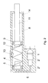
- Fig. 2 shows a mechanical embodiment by means of a spring.
- a electric detonator 1 and a propellant charge 2 in one housing 2 'housed are a electric detonator 1 and a propellant charge 2 in one housing 2 'housed. If the electric igniter 1 is ignited, then the propellant charge 2 burns off. The resulting gases arrive through an opening 3 in the housing 2 'on the end face a first piston 5, which is displaceable in a first cylinder 4 is.
- the space behind the first piston 5 is with Hydraulic oil 10 filled.
- the gas pressure becomes the first Piston 5 shifted to the left and presses hydraulic oil 10 into a channel 6.
- the channel 6 is with a second cylinder 8 in connection, in which a second piston 9 is displaceable is. Hydraulic oil 10 thus makes second piston 9 shifted to the right.
- the second piston 9 has a larger cross-sectional area than the first piston 5. As a result, the second piston 9 moves slower than the first piston 5, so an additional Slowing the movement is achieved.
- the gas pressure that arises when the propellant charge 2 burns off the first piston 5 is moved to the right and thereby the compression spring 12 tensioned.
- a pawl 13 is provided which prevents the first piston 5 from moving back, once he has moved all the way to the right.
- the second Piston 9 is then followed by the tensioned compression spring 12 moved to the right. His movement is hindered by that it is guided airtight in the second cylinder 8, so that an overpressure builds up to the right of the second piston 9.
- the compressed air can only pass slowly through a damping hole 14 escape.
- the dimensions of the damping bore 14 thus determine the speed at which the piston rod moves 11 moved to the right. Since the piston rod 11 the neck support The speed is also shifted forward the displacement of the headrest.
Landscapes
- Engineering & Computer Science (AREA)
- Chemical & Material Sciences (AREA)
- Analytical Chemistry (AREA)
- Physics & Mathematics (AREA)
- Fluid Mechanics (AREA)
- Mechanical Engineering (AREA)
- General Engineering & Computer Science (AREA)
- Automotive Seat Belt Assembly (AREA)
- Seats For Vehicles (AREA)
- Fluid-Damping Devices (AREA)
Abstract
Description
Die vorliegende Erfindung betrifft ein Verzögerungselement, das die Wirkung des Gasdrucks, der beim Abbrand einer pyrotechnischen Ladung entsteht, auf eine etwas längere Zeit verteilt, insbesondere als Antrieb zur Verstellung von Nackenstützen im Falle eines Unfalls.The present invention relates to a delay element, which is the effect of the gas pressure that occurs when a pyrotechnic Charge arises, distributed over a somewhat longer time, especially as a drive for adjusting neck supports in case of an accident.
In der Sicherheitstechnik von Kraftfahrzeugen wird in zunehmendem Maße Pyrotechnik eingesetzt. Am häufigsten wird die Pyrotechnik zum Aufblasen von Air-Bags eingesetzt.In the safety technology of motor vehicles is increasing Dimensions pyrotechnics used. The most common is Pyrotechnics used to inflate air bags.
Mittlerweile wird sie aber auch zum Straffen von Sicherheitsgurten im Falle eines Unfalles zunehmend verwendet. Dazu wird ein Kolben mit dem Gasdruck, der beim Abbrand der pyrotechnischen Ladung entsteht, beaufschlagt. Dieser wird infolge des Gasdrucks verschoben und zieht dadurch das Gurtschloß zurück, sodass sich der Gurt spannt. In der zurückgezogenen Stellung wird das Gurtschloss dann arretiert.In the meantime, however, it is also used to tighten seat belts increasingly used in the event of an accident. To becomes a piston with the gas pressure that burns when the pyrotechnic Charge arises, acted upon. This will result the gas pressure shifted and pulls the buckle back so that the belt tightens. In the withdrawn The belt buckle is then locked in position.
Bei dieser Anwendung ist es ziemlich gleichgültig, wie schnell das Gurtschloss zurückgezogen wird, es muss nur ausreichend schnell sein, damit der Gurt gestrafft ist, bevor die Person, die vom Gurt gehalten werden soll, in den Gurt fällt.With this application, it is pretty indifferent to how the belt buckle is pulled back quickly, it only has to be sufficient be quick so that the belt is tightened before the person to be held by the belt in the belt falls.
Ein weiteres Anwendungsgebiet, wo Pyrotechnik zum Einsatz gelangen könnte, sind die Nackenstützen. Nackenstützen befinden sich in der normalen Stellung in einigen Zentimetern Abstand vom Kopf entfernt (üblich sind 6,5 cm). Dies hat Komfortgründe: würde die Nackenstütze ständig am Kopf anliegen, so wäre dies unangenehm, außerdem würde dies beim Rückwärtsfahren, wenn sich der Fahrer umdreht, die Sicht einschränken.Another area of application where pyrotechnics are used the neck supports. Neck supports in the normal position a few centimeters away away from the head (6.5 cm is common). This has reasons of comfort: the headrest would be constantly on the head, it would be uncomfortable if the driver turns around, restrict the view.
Es ist daher schon vorgeschlagen worden, die Nackenstützen im Falle eines Unfalls um einige Zentimeter nach vorne zu bewegen. Am Markt ist ein mechanisches System: wenn bei einem Heckaufprall die Person in den Sitz (gegen die Rückenlehne) gedrückt wird, dann wird durch ein Hebelsystem in der Rückenlehne die Nackenstütze nach vorne bewegt. Der wesentliche Nachteil dieses System besteht darin, dass die Bewegung der Nackenstütze sehr spät erfolgt: wenn der Oberkörper der Person in den Sitz gedrückt wird, bewegt sich auch schon deren Kopf in Richtung Nackenstütze. Dadurch ist der Aufprall besonders stark. Es wäre besser, wenn die Nackenstütze vorwärts bewegt wird, bevor sich der Kopf infolge des Aufpralls in Bewegung setzt.It has therefore already been suggested the neck supports move forward a few centimeters in the event of an accident. There is a mechanical system on the market: if at one Rear impact the person in the seat (against the backrest) is then pressed by a lever system in the backrest the headrest moves forward. The essential Disadvantage of this system is that the movement of the Neck support occurs very late: when the person's upper body is pressed into the seat, theirs already moves Head towards the neck support. This makes the impact special strong. It would be better if the neck support were forward is moved before the head moves due to the impact puts.
Es ist daher auch schon vorgeschlagen worden, für eine derart schnelle Bewegung Pyrotechnik einzusetzen (s. die EP 826 553 A). Versuche haben aber gezeigt, dass die Pyrotechnik für diese Anwendung schneller als erwünscht ist: die Nackenstütze bewegt sich derartig schnell nach vorne, dass sie - wenn die Person den Kopf zufällig gerade etwas weiter hinten als vorgesehen hat - so schnell auf den Kopf schlägt, dass bereits dadurch Verletzungen möglich sind.It has therefore already been proposed for such a use rapid motion pyrotechnics (see EP 826 553 A). However, tests have shown that pyrotechnics is faster than desired for this application: the Neck support moves forward so quickly that them - if the person's head just happens to be a little further in the back as planned - hitting the head so quickly, that injuries are already possible.
Man kann zwar die Abbrandgeschwindigkeit pyrotechnischer Ladungen in gewissen Grenzen durch chemische Zusätze verlangsamen, aber für die Anwendung bei Nackenstützen ist diese Verzögerung nicht ausreichend.The burning rate can be pyrotechnic Slow charges within certain limits by chemical additives, but this is for use with neck supports Delay not sufficient.
Es ist somit Aufgabe der vorliegenden Erfindung, ein Verzögerungselement zu schaffen, das die Wirkung des Gasdrucks, der beim Abbrand einer pyrotechnischen Ladung entsteht, auf eine etwas längere Zeit verteilt, um eine Nackenstütze mit optimaler Geschwindigkeit zu verstellen.It is therefore an object of the present invention to provide a delay element to create the effect of gas pressure, that arises when a pyrotechnic charge burns up spread out a little longer to use a neck support optimal speed to adjust.
Diese Aufgabe wird durch ein Verzögerungselement der eingangs genannten Art erfindungsgemäß dadurch gelöst, dass der Gasdruck auf einen ersten Kolben wirkt, der mit seiner gegenüberliegenden Stirnfläche auf Hydrauliköl drückt, welches seinerseits auf einen zweiten Kolben wirkt, wobei im Kanal des Hydrauliköls eine Verengung vorgesehen ist. Das Hydrauliköl kann auf Grund seiner Zähigkeit und der Verengung nicht allzu schnell strömen; auf diese Weise bewegen sich die beiden Kolben mit nahezu konstanter Geschwindigkeit, bis sie den gesamten Verstellweg durchlaufen haben. Die Geschwindigkeit kann durch Einstellung der Verengung variiert werden.This task is accomplished by a delay element at the beginning mentioned type solved according to the invention in that the Gas pressure acts on a first piston, the one with its opposite one Face presses on hydraulic oil, which in turn acts on a second piston, being in the channel a restriction of the hydraulic oil is provided. The hydraulic oil cannot because of its toughness and narrowing streaming too quickly; this is how the two move Piston at almost constant speed until it reaches the have run through the entire adjustment range. The speed can be varied by adjusting the constriction.
Es ist dabei zweckmäßig, wenn im ersten Kolben eine Bohrung vorgesehen ist, die als Zylinderbohrung für den zweiten Kolben dient, sodass die beiden Kolben ineinander liegen. Auf diese Weise ist der Platzbedarf für das Verzögerungselement minimal.It is useful if there is a bore in the first piston is provided as a cylinder bore for the second piston serves, so that the two pistons lie in each other. On this is the space requirement for the delay element minimal.
Eine weitere Lösung der Aufgabe der vorliegenden Erfindung besteht darin, dass der Gasdruck auf einen ersten Koben wirkt, auf dessen gegenüberliegende Stirnfläche sich eine Druckfeder abstützt, die mit ihrem anderen Ende auf einen zweiten Kolben wirkt, wobei dieser zweite Kolben in einem zweiten Zylinder luftdicht geführt ist und im zweiten Zylinder eine Dämpfungsbohrung vorgesehen ist. Bei dieser Ausführungsform können sich die beiden Kolben unterschiedlich schnell bewegen. Der erste Kolben bewegt sich auf Grund des von der pyrotechnischen Ladung erzeugten Gasdrucks sehr schnell und spannt dadurch die Feder. Der zweite Kolben bewegt sich nun auf Grund der Federkraft, wird aber durch den Überdruck, der sich im zweiten Zylinder aufbaut, gedämpft. Der Überdruck kann sich nur langsam durch die Dämpfungsbohrung abbauen, sodass auch hier eine beliebig wählbare Verzögerung erzielt werden kann. (Die Verzögerung hängt von der Größe der Dämpfungsbohrung ab.)Another solution to the problem of the present invention is that the gas pressure on a first piston acts on the opposite end face Compression spring supports with its other end on one second piston acts, this second piston in one second cylinder is airtight and in the second cylinder a damping hole is provided. In this embodiment the two pistons can be different to move fast. The first piston moves due to the gas pressure generated by the pyrotechnic charge very much quickly and thereby tension the spring. The second piston moves now due to the spring force, but is replaced by the Overpressure that builds up in the second cylinder is damped. The overpressure can only slowly pass through the damping hole dismantle, so that here you can choose any delay can be achieved. (The delay depends on the Size of the damping bore.)
Anhand der beiliegenden Zeichnungen wird die vorliegende Erfindung näher erläutert. Es zeigt: Fig. 1 eine hydraulische Ausführungsform und Fig. 2 eine mechanische Ausführungsform mittels einer Feder.Based on the accompanying drawings, the present Invention explained in more detail. 1 shows a hydraulic one Embodiment and Fig. 2 shows a mechanical embodiment by means of a spring.
Bei der hydraulischen Ausführungsform (s. Fig. 1) sind ein
elektrischer Zünder 1 und eine Treibladung 2 in einem Gehäuse
2' untergebracht. Wird der elektrische Zünder 1 gezündet,
dann brennt die Treibladung 2 ab. Die entstehenden Gase gelangen
durch eine Öffnung 3 im Gehäuse 2' auf die Stirnfläche
eines ersten Kolbens 5, der in einem ersten Zylinder 4 verschiebbar
ist. Der Raum hinter dem ersten Kolben 5 ist mit
Hydrauliköl 10 gefüllt. Durch den Gasdruck wird der erste
Kolben 5 nach links verschoben und drückt das Hydrauliköl 10
in einen Kanal 6. Der Kanal 6 steht mit einem zweiten Zylinder
8 in Verbindung, in dem ein zweiter Kolben 9 verschiebbar
ist. Durch das Hydrauliköl 10 wird somit der zweite Kolben 9
nach rechts verschoben.In the hydraulic embodiment (see Fig. 1) are a
In den Kanal 6 ragt eine Schraube 7, die eine Verengung des
Kanals 6 bewirkt. Durch diese Verengung wird die Fließgeschwindigkeit
des Hydrauliköls 10 reduziert, und durch Verstellung
der Schraube 7 lässt sich die Fließgeschwindigkeit
einstellen. Durch die begrenzte Fließgeschwindigkeit des Hydrauliköls
10 wird auch die Geschwindigkeit, mit der sich die
beiden Kolben 5 und 9 bewegen, entsprechend reduziert. Auch
die Größe der Öffnung 3 hat Einfluss auf diese Geschwindigkeit:
je kleiner die Öffnung 3 ist, umso langsamer strömt das
Gas zum ersten Kolben 5 und umso langsamer ist die Bewegung
der beiden Kolben 5,9.In the
Der zweite Kolben 9 hat eine größere Querschnittsfläche als
der erste Kolben 5. Dadurch bewegt sich der zweite Kolben 9
langsamer als der erste Kolben 5, sodass eine zusätzliche
Verlangsamung der Bewegung erzielt wird.The
Zur Verstellung von Nackenstützen kann man mit der Kolbenstange
11 des zweiten Kolbens 9 eine Kulisse verbinden, durch
deren Verschiebung wird dann die Neigung der Nackenstützen um
eine waagrechte Achse, die sich im Inneren der Rückenlehne
befindet, verändert. Die Kulisse muss dabei waagrecht verschoben
werden, d.h. die Anordnung des Verzögerungselements
erfolgt in der Rückenlehne so wie dargestellt. Die Gesamtlänge
darf daher nicht zu groß sein, aus diesem Grunde ist
der Kanal 6 abgewinkelt ausgeführt, sodass die beiden Zylinder
4 und 8 nebeneinander liegen. Eine noch Platz sparendere
Ausführungsform wäre, die beiden Kolben ineinander anzuordnen,
d.h. der erste Kolben hätte dann eine Mittelbohrung, die
als Zylinder für den zweiten Kolben dient.You can use the piston rod to adjust the neck supports
11 of the
Bei der Ausführungsform mit Feder (s. Fig. 2) sind auch ein
Zünder 1 und eine Treibladung 2 in einem Gehäuse 2' untergebracht.
Die beim Abbrennen der Treibladung 2 entstehenden
Gase gelangen direkt (ohne Mitwirkung eines Hydrauliköls)
durch einen Kanal 6 zur Stirnfläche eines ersten Kolbens 5.
Dieser ist in einem ersten Zylinder 4 verschiebbar. An der
gegenüberliegenden Stirnfläche des ersten Kolbens 5 greift
eine Druckfeder 12 an, die sich mit ihrem anderen Ende an einem
zweiten Kolben 9 abstützt. Dieser zweite Kolben 9 ist in
einem zweiten Zylinder 8 verschiebbar. In der dargestellten
Ausführungsform ist der zweite Zylinder 8 die unmittelbare
Verlängerung des ersten Zylinders 4; es ist aber auch möglich,
ihn mit einem anderen Durchmesser auszubilden.In the embodiment with spring (see Fig. 2) are also a
Igniter 1 and a
Durch den Gasdruck, der beim Abbrand der Treibladung 2 entsteht,
wird der erste Kolben 5 nach rechts bewegt und dadurch
die Druckfeder 12 gespannt. Es ist eine Klinke 13 vorgesehen,
die den ersten Kolben 5 daran hindert, sich zurückzubewegen,
sobald er sich einmal ganz nach rechts bewegt hat. Der zweite
Kolben 9 wird dann von der gespannten Druckfeder 12 nach
rechts bewegt. Er wird in seiner Bewegung dadurch gehindert,
dass er luftdicht im zweiten Zylinder 8 geführt ist, sodass
sich rechts vom zweiten Kolben 9 ein Überdruck aufbaut. Die
komprimierte Luft kann nur langsam durch eine Dämpfungsbohrung
14 entweichen. Die Abmessungen der Dämpfungsbohrung 14
bestimmen somit die Geschwindigkeit, mit der sich die Kolbenstange
11 nach rechts bewegt. Da die Kolbenstange 11 die Nackenstütze
nach vorn verschiebt, wird damit auch die Geschwindigkeit
der Verschiebung der Nackenstütze festgelegt.The gas pressure that arises when the
Erste Versuche mit solchen Verzögerungselementen lieferten sehr viel versprechende Ergebnisse. Es ist möglich, die Geschwindigkeit der Bewegung der Nackenstütze präzise so einzustellen, dass die Bewegung genau in dem Augenblick vollendet ist, in dem der Kopf infolge des Heckaufpralls die Nackenstütze berührt. Es erfolgt dabei eine Bewegung um 40 mm in 25 ms.Initial attempts with such delay elements delivered very promising results. It is possible the speed precisely adjust the movement of the neck support so that the movement is completed at that very moment in which the head is the headrest due to the rear impact touched. There is a movement of 40 mm in 25 ms.
Claims (3)
Applications Claiming Priority (2)
| Application Number | Priority Date | Filing Date | Title |
|---|---|---|---|
| AT103398 | 1998-06-16 | ||
| AT103398A AT405729B (en) | 1998-06-16 | 1998-06-16 | Delay element for pyrotechnic charges |
Publications (2)
| Publication Number | Publication Date |
|---|---|
| EP0965483A2 true EP0965483A2 (en) | 1999-12-22 |
| EP0965483A3 EP0965483A3 (en) | 2001-09-26 |
Family
ID=3505193
Family Applications (1)
| Application Number | Title | Priority Date | Filing Date |
|---|---|---|---|
| EP99890091A Withdrawn EP0965483A3 (en) | 1998-06-16 | 1999-03-11 | Delay element for pyrotechnical charge |
Country Status (2)
| Country | Link |
|---|---|
| EP (1) | EP0965483A3 (en) |
| AT (1) | AT405729B (en) |
Cited By (2)
| Publication number | Priority date | Publication date | Assignee | Title |
|---|---|---|---|---|
| WO2006010562A3 (en) * | 2004-07-23 | 2006-04-27 | Delphi Tech Inc | Pyrotechnic actuator |
| US10059577B2 (en) | 2014-04-14 | 2018-08-28 | Daicel Corporation | Perforator and gas discharge apparatus |
Citations (1)
| Publication number | Priority date | Publication date | Assignee | Title |
|---|---|---|---|---|
| EP0826553A2 (en) | 1996-08-28 | 1998-03-04 | TRW Occupant Restraint Systems GmbH | Vehicle seat with a headrest, adjustably mounted on the backrest |
Family Cites Families (4)
| Publication number | Priority date | Publication date | Assignee | Title |
|---|---|---|---|---|
| DE2232726A1 (en) * | 1972-07-04 | 1974-01-24 | Volkswagenwerk Ag | SAFETY DEVICE |
| JPS4987971A (en) * | 1972-12-27 | 1974-08-22 | ||
| DE3717458A1 (en) * | 1987-05-23 | 1988-12-01 | Diehl Gmbh & Co | Pyrotechnic force element |
| FR2685741A1 (en) * | 1991-12-31 | 1993-07-02 | Thomson Brandt Armements | PYROTECHNIC CYLINDER WITH AMORTIZED RUN. |
-
1998
- 1998-06-16 AT AT103398A patent/AT405729B/en not_active IP Right Cessation
-
1999
- 1999-03-11 EP EP99890091A patent/EP0965483A3/en not_active Withdrawn
Patent Citations (1)
| Publication number | Priority date | Publication date | Assignee | Title |
|---|---|---|---|---|
| EP0826553A2 (en) | 1996-08-28 | 1998-03-04 | TRW Occupant Restraint Systems GmbH | Vehicle seat with a headrest, adjustably mounted on the backrest |
Cited By (2)
| Publication number | Priority date | Publication date | Assignee | Title |
|---|---|---|---|---|
| WO2006010562A3 (en) * | 2004-07-23 | 2006-04-27 | Delphi Tech Inc | Pyrotechnic actuator |
| US10059577B2 (en) | 2014-04-14 | 2018-08-28 | Daicel Corporation | Perforator and gas discharge apparatus |
Also Published As
| Publication number | Publication date |
|---|---|
| ATA103398A (en) | 1999-03-15 |
| AT405729B (en) | 1999-11-25 |
| EP0965483A3 (en) | 2001-09-26 |
Similar Documents
| Publication | Publication Date | Title |
|---|---|---|
| DE19707998B4 (en) | Automotive seat | |
| DE2024749C3 (en) | Device for continuously adjusting the inclination of the backrest of seats, in particular motor vehicle seats | |
| DE10011829C2 (en) | Actuator for a vehicle occupant restraint system | |
| DE60118079T2 (en) | Protection device for vehicle occupants | |
| EP1427603B1 (en) | Backrest for a vehicle seat | |
| DE2253657C2 (en) | Device for tensioning seat belts in vehicles | |
| DE102006061427B4 (en) | Method and belt tensioning system for restraining occupants of a vehicle in the event of an impact with an obstacle | |
| DE102007000747A1 (en) | Headrest movement device for a motor vehicle | |
| DE19952771A1 (en) | Child's active vehicle safety seat with an integrated shock absorber system to reduce the energy of heavy braking and thus injury to the child | |
| DE2366271C2 (en) | Pulling device operated by a propellant charge | |
| DE2408173A1 (en) | SEAT BELT SYSTEM WITH SERVO MOTOR | |
| DE60121278T2 (en) | Personal protection system in the motor vehicle | |
| EP0916557A2 (en) | Buckle retractor | |
| EP0979182A2 (en) | Automobile airbag system | |
| DE2016761A1 (en) | Vehicle security device | |
| EP0965483A2 (en) | Delay element for pyrotechnical charge | |
| DE10150899B4 (en) | Backrest for vehicle seat | |
| DE2415769A1 (en) | Hydraulic seat mounting for smooth adjustment - fitted with spring loaded safety valves for absorbing impact forces | |
| DE102005043706B4 (en) | Restraint system | |
| DE19957794C2 (en) | Seat belt arrangement in vehicles | |
| DE10061043A1 (en) | Impact resistance actuator for motor vehicle seat drives seat in reverse direction to impact induced movement | |
| DE112014003724T5 (en) | Dual-chamber passenger airbag | |
| EP3042144A1 (en) | Headrest for a vehicle seat | |
| DE2308343A1 (en) | BRACKET FOR HUMAN BODIES ON SEATS OF MOTOR VEHICLES | |
| DE102006052332A1 (en) | Drive unit for tightening system of seat belt arrangement, has cylinder and piston supported to move axially in cylinder |
Legal Events
| Date | Code | Title | Description |
|---|---|---|---|
| PUAI | Public reference made under article 153(3) epc to a published international application that has entered the european phase |
Free format text: ORIGINAL CODE: 0009012 |
|
| AK | Designated contracting states |
Kind code of ref document: A2 Designated state(s): AT BE CH CY DE DK ES FI FR GB GR IE IT LI LU MC NL PT SE Kind code of ref document: A2 Designated state(s): AT DE ES FR GB IT |
|
| AX | Request for extension of the european patent |
Free format text: AL;LT;LV;MK;RO;SI |
|
| PUAL | Search report despatched |
Free format text: ORIGINAL CODE: 0009013 |
|
| AK | Designated contracting states |
Kind code of ref document: A3 Designated state(s): AT BE CH CY DE DK ES FI FR GB GR IE IT LI LU MC NL PT SE |
|
| AX | Request for extension of the european patent |
Free format text: AL;LT;LV;MK;RO;SI |
|
| RIC1 | Information provided on ipc code assigned before grant |
Free format text: 7B 60N 2/48 A, 7F 15B 15/19 B |
|
| 17P | Request for examination filed |
Effective date: 20020207 |
|
| AKX | Designation fees paid |
Free format text: AT DE ES FR GB IT |
|
| 17Q | First examination report despatched |
Effective date: 20031208 |
|
| STAA | Information on the status of an ep patent application or granted ep patent |
Free format text: STATUS: THE APPLICATION IS DEEMED TO BE WITHDRAWN |
|
| 18D | Application deemed to be withdrawn |
Effective date: 20050806 |