EP0965479B1 - Vehicle Seat Assembly - Google Patents
Vehicle Seat Assembly Download PDFInfo
- Publication number
- EP0965479B1 EP0965479B1 EP99630052A EP99630052A EP0965479B1 EP 0965479 B1 EP0965479 B1 EP 0965479B1 EP 99630052 A EP99630052 A EP 99630052A EP 99630052 A EP99630052 A EP 99630052A EP 0965479 B1 EP0965479 B1 EP 0965479B1
- Authority
- EP
- European Patent Office
- Prior art keywords
- seat
- power unit
- vehicle seat
- assembly
- seat assembly
- Prior art date
- Legal status (The legal status is an assumption and is not a legal conclusion. Google has not performed a legal analysis and makes no representation as to the accuracy of the status listed.)
- Expired - Lifetime
Links
Images


Classifications
-
- B—PERFORMING OPERATIONS; TRANSPORTING
- B60—VEHICLES IN GENERAL
- B60N—SEATS SPECIALLY ADAPTED FOR VEHICLES; VEHICLE PASSENGER ACCOMMODATION NOT OTHERWISE PROVIDED FOR
- B60N2/00—Seats specially adapted for vehicles; Arrangement or mounting of seats in vehicles
- B60N2/24—Seats specially adapted for vehicles; Arrangement or mounting of seats in vehicles for particular purposes or particular vehicles
- B60N2/42—Seats specially adapted for vehicles; Arrangement or mounting of seats in vehicles for particular purposes or particular vehicles the seat constructed to protect the occupant from the effect of abnormal g-forces, e.g. crash or safety seats
- B60N2/427—Seats or parts thereof displaced during a crash
- B60N2/42727—Seats or parts thereof displaced during a crash involving substantially rigid displacement
- B60N2/42754—Seats or parts thereof displaced during a crash involving substantially rigid displacement of the cushion
- B60N2/42763—Seats or parts thereof displaced during a crash involving substantially rigid displacement of the cushion with anti-submarining systems
-
- B—PERFORMING OPERATIONS; TRANSPORTING
- B60—VEHICLES IN GENERAL
- B60N—SEATS SPECIALLY ADAPTED FOR VEHICLES; VEHICLE PASSENGER ACCOMMODATION NOT OTHERWISE PROVIDED FOR
- B60N2/00—Seats specially adapted for vehicles; Arrangement or mounting of seats in vehicles
- B60N2/24—Seats specially adapted for vehicles; Arrangement or mounting of seats in vehicles for particular purposes or particular vehicles
- B60N2/42—Seats specially adapted for vehicles; Arrangement or mounting of seats in vehicles for particular purposes or particular vehicles the seat constructed to protect the occupant from the effect of abnormal g-forces, e.g. crash or safety seats
- B60N2/4207—Seats specially adapted for vehicles; Arrangement or mounting of seats in vehicles for particular purposes or particular vehicles the seat constructed to protect the occupant from the effect of abnormal g-forces, e.g. crash or safety seats characterised by the direction of the g-forces
- B60N2/4214—Seats specially adapted for vehicles; Arrangement or mounting of seats in vehicles for particular purposes or particular vehicles the seat constructed to protect the occupant from the effect of abnormal g-forces, e.g. crash or safety seats characterised by the direction of the g-forces longitudinal
- B60N2/4221—Seats specially adapted for vehicles; Arrangement or mounting of seats in vehicles for particular purposes or particular vehicles the seat constructed to protect the occupant from the effect of abnormal g-forces, e.g. crash or safety seats characterised by the direction of the g-forces longitudinal due to impact coming from the front
-
- B—PERFORMING OPERATIONS; TRANSPORTING
- B60—VEHICLES IN GENERAL
- B60N—SEATS SPECIALLY ADAPTED FOR VEHICLES; VEHICLE PASSENGER ACCOMMODATION NOT OTHERWISE PROVIDED FOR
- B60N2/00—Seats specially adapted for vehicles; Arrangement or mounting of seats in vehicles
- B60N2/24—Seats specially adapted for vehicles; Arrangement or mounting of seats in vehicles for particular purposes or particular vehicles
- B60N2/42—Seats specially adapted for vehicles; Arrangement or mounting of seats in vehicles for particular purposes or particular vehicles the seat constructed to protect the occupant from the effect of abnormal g-forces, e.g. crash or safety seats
- B60N2/427—Seats or parts thereof displaced during a crash
- B60N2/42772—Seats or parts thereof displaced during a crash characterised by the triggering system
- B60N2/4279—Seats or parts thereof displaced during a crash characterised by the triggering system electric or electronic triggering
Definitions
- the present invention relates to a vehicle seat assembly, and in particular to a vehicle seat assembly which is adapted to prevent a vehicle occupant from slipping forward under a seat belt in case of an impact such as a vehicle crash.
- United States Patent No. 5,340,185 discloses a seat assembly using a wire and pulley arrangement for converting a forward movement of the seat in case of a vehicle crash into a lifting movement of the front edge of the seat.
- This arrangement uses the inertia force as a power source for actuating the front edge of the seat, and is advantageous in not requiring any other power source.
- the arrangement is highly complex, and there would be considerable difficulty in achieving a successful design.
- Japanese utility model laid open publication No. 3-61440 discloses a similar seat assembly relying on a propellant as a power source for selectively raising the front edge of the vehicle seat.
- An automobile is often equipped with an emergency locking retractor (ELR) which locks up a winding shaft for the seat belt in case of a sudden stop or a vehicle crash.
- An ELR device is capable of locking up the winding shaft in a very short time upon detecting a deceleration level greater than a prescribed value so as to prevent any further pay-out of the seat belt.
- simply locking up the winding shaft would not prevent a pay-out of a length of the seat belt corresponding to the tightening of the part of the seat belt wound on the winding shaft.
- a pretensioner device proposed in the United States Patent No. 4,705,296, the buckle which is attached to an end of the seat belt is rapidly moved in the direction to tension the seat belt to enhance the restraining capability of the seat belt.
- the pretensioner device is provided with a reversing preventing device such as a ratchet and a one-way clutch, separately from that of the ELR device.
- a reversing preventing device such as a ratchet and a one-way clutch
- Such a pretensioner device is typically provided with a power unit for pulling the buckle powered by high pressure gas produced from a chemical reaction, for instance, as was the case with the invention disclosed in Japanese patent laid open publication No. 10-181529 by the same applicant.
- a vehicle seat assembly as defined in the precharacterizing portion of independent claim 1 is disclosed in DE-A-36 31 881.
- a spreading scissors-like linkage has a first arm mounted on a fixed part of the seat and a second arm mounted at the leading end to a deformable member of the seat cushion.
- An actuator is connected to the interconnected ends of the two arms of the linkage and the linkage is designed to lock in the spreaded position.
- a primary object of the present invention is to provide a vehicle seat assembly which provides a sitting comfort under normal condition, but can prevent a submarine phenomenon in a reliable manner.
- a second object of the present invention is to provide a vehicle seat assembly which is simple in structure so as to allow a high level of flexibility in layout.
- a third object of the present invention is to provide a vehicle seat assembly which is economical to manufacture.
- a vehicle seat assembly comprising a slip preventing member supported by a fixed part of a seat so as to be pivotable between a retracted position and a raised position; a power unit comprising a cylinder and a piston assembly being interposed between a fixed part of said seat and a part of said slip preventing member, and adapted to move said slip preventing member toward said raised position, and a one-way lock mechanism for retaining said slip preventing member at said raised position; characterized in that said lock mechanism is incorporated in the power unit and is acting on a piston or on a piston rod of the piston assembly.
- the slip preventing member may comprise a lever member supported by a fixed part of the seat so as to be pivotable around a laterally extending pivot shaft, and a rod member extending along a front edge of the seat and attached to a free end of the lever member.
- the slip preventing member comprises a pair of lever members supported on either side of the seat by a fixed part of the seat so as to be pivotable around a laterally extending pivot shaft, and a rod member extending along a front edge of the seat and attached across free ends of the lever members.
- at least one of the lever members preferably consists of a bell crank having a first end attached to the rod member, and a second end adapted to be actuated by the actuator which typically consists of a piston/cylinder arrangement including a propellant.
- the pretensioner device may comprise a bell crank member which is pivotally supported by a fixed part of the seat so as to be pivotable around a pivot shaft extending laterally with respect the seat, the bell crank member having a first end attached to the buckle, and a second end attached to an end of the actuator which is common to the submarine preventing arrangement.
- FIG 1 is a perspective view of a vehicle seat assembly S embodying the present invention
- Figure 2 is a partly broken away side view of this vehicle seat assembly S.
- a seat frame 2 is supported by seat rails 1 fixedly attached to the vehicle body so as to be slidable in the fore-and-aft direction, and can be selectively secured at a desired position by a lock mechanism not shown in the drawings. So far, the seat assembly is quite conventional.
- the L-shaped link member 3 includes a long arm section 3a and a short arm section 3b, and is pivotally supported at the intersection or the bent portion by the pivot shaft 5.
- the arm 4 can be considered as consisting solely of a long arm section, and is supported by the scat frame 2 at a base end thereof by the pivot shaft 5 which is hidden from view in Figure 1.
- the arm 4 can also consist of a bell crank identical to the L-shaped link member 3 for reducing the variations in the component parts although the short arm section of the bell crank 4 may not serve any useful purpose in that case.
- the free ends of the long arm section 3a of the L-shaped link member 3 and the arm 4 are joined by a bar 6 extending laterally along a front edge of the seat, and serving as a main part of the slip preventing member.
- the free end of the short arm section 3b of the link member 3 is pivotally connected to a free end 9a of a piston assembly 9 of a power unit 7.
- the free end of the short arm section 3b of the link member 3 is provided with an elongated slot so as to accommodate the arcuate motion of the link member 3 to the linear motion of the piston assembly 9.
- the power unit 7 comprises a cylinder 8 fixedly secured to the seat frame 2, a piston 9b which is slidably received in the cylinder 8, and a gas generator 10 received in the cylinder 8 on the base end of the piston. 9b.
- a collar 11 is interposed between the piston 9b and the gas generator 10.
- the piston 9b engages the wall surface of the bore of the cylinder 8 via an O-ring. Therefore, by rapidly increasing the inner pressure of the cylinder 8 with the gas generator 10, the free end 9a of the piston assembly 9 may be projected from the cylinder 8 at high speed.
- the opening on the working end (left end) of the cylinder 8 is reduced in diameter by swaging so as to engage the outer circumferential surface of the intermediate part of a piston rod 9c of the piston assembly 9.
- a ball-type one-way lock mechanism is incorporated in the power unit 7 for retaining the bar 6 serving as the slip preventing member at its raised position.
- a casing 23 is fixedly secured to the cylinder 8 or the seat frame 2 so as to surround the outer periphery of the piston rod 9c, and a number of balls 24 and springs 25 for urging the balls 24 in the direction to retract the piston rod 9c are received in a chamber defined between the piston rod 9c and the casing 23.
- the inner wall of the casing 23 is inclined to make the chamber narrower on the side of the base end of the piston assembly 9 than on the side of the free end of the piston assembly 9.
- the piston assembly 9 is allowed to move freely in the projecting direction to raise the bar 6 but prohibited from moving into the cylinder 8 because the balls 24 wedge into a gap defined between the piston rod 9c and the wall surface of the casing 23, and prevent any further movement of the piston assembly 9 thus preventing the bar 6 from moving down.
- the ball-type one-way lock mechanism prevents the raised bar 6 from moving down, and thereby maintains the capability to prevent the submarine phenomenon.
- a chamber is defined inside the cylinder 8 of the power unit 7 between the inner wall surface of the cylinder 8 and the piston 9b, and a number of balls 26 and springs 27 for urging the balls 26 in the direction to oppose the retracting influence of the piston assembly 9 are received in this chamber.
- the outer circumferential surface of the piston 9b defines an inclined surface inside the chamber in such a manner that the chamber gets narrower from the base end of the piston assembly to the free end thereof.
- the lock mechanism is incorporated in the power unit 7.
- a casing 28 is fixedly secured to the cylinder 8 or the seat frame 2 so as to surround the outer periphery of the piston rod 9b, and a number of engagement pieces 29 and spring 30 for urging the engagement pieces 29 toward the base end of the piston 9b or toward the cylinder 8 are received inside the casing 28.
- the outer peripheral surface of each of the engagement pieces 29 is gradually diminished in outer diameter from the free end of the piston assembly 9 to the base end thereof.
- the interior of the casing 28 includes a large diameter section 28a and a tapered section 28b which is progressively reduced in diameter away from the large diameter section 28a.
- the engagement pieces 29 engage the outer circumferential surface of the piston 9 because the engagement pieces 29 are urged by the spring 30 and pressed upon by the tapered section 28b as a result in the state illustrated in Figure 5.
- the engagement pieces 29 are moved in the projecting direction of the piston assembly 9 against the urging force of the spring 30 until they reach the large diameter section 28a, thereby disengaging themselves from the piston rod 9c, and allowing the piston assembly 9 to move freely.
- Figure 6 is a view similar to Figure 2 showing another embodiment of the present invention.
- the parts corresponding to those in Figure 2 are denoted with like numerals without repeating a detailed description of such parts.
- the power unit 2 shown in Figure 2 additionally serves as a power unit for moving a buckle of a seat belt in the tensioning direction in a pretensioner device 31 for automatically tensioning a seat belt in case of a vehicle crash.
- the ball-type one-way lock mechanism of Figure 3 described above or the modified embodiments thereof ( Figures 4 and 5) additionally serves as a lock mechanism for retaining the buckle 32 of the seat belt at a position for maintaining a tension in the seat belt.
- the pretensioner device 31 comprises a bell crank or a rotary arm 34 pivotally attached to a side of the seat so as to be rotatable around a laterally extending pivot axis.
- the rotary arm 34 is provided with a first end which is pivotally attached to a base end of the buckle 32, and a second send which is pivotally attached to a link member 33 which is in turn pivotally attached to the free end 9a of the piston assembly 9 of the power unit 7.
- the buckle 32 As the bar 6 moves or projects upward, the buckle 32 is pulled downward as indicated by the imaginary line at the same time, applying a tension to the seat belt and increasing the restraining force for me vehicle occupant. Even when the drive force of the power unit 7 is all spent, the ball-type one-way lock mechanism of Figure 3 or the modifications thereof ( Figures 4 and 5) prevents the reversing of the buckle 32 or the slackening of the seat belt.
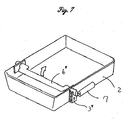
- the link member 3 consisted of an L-shaped member in the above described embodiments, it is also possible to rotatably support a bar 6' having a C-shaped middle section which is provided with a lever 3' at an end thereof as illustrated in Figure 7, and to drive this lever 3' with the power unit 7 so as to selectively raise the C-shaped part of the bar 6'.
- the output end of the power unit 7 is connected to the lever 3' via a pin and slot arrangement similar to that shown in Figure 2.
- a slip preventing member for preventing the vehicle occupant from slipping forward under the seat belt in case of an impact is either directly or indirectly connected to a power unit which can project a piston received in a cylinder with gas generating means in such a manner that the slip preventing member is projected upward upon detecting an impact to the vehicle, and is retained at its projected state with a lock mechanism. Therefore, in a case of an impact, a submarine phenomenon can be prevented in a reliable manner, and the simplicity in structure allows a high level of flexibility in layout.
- the power unit additionally serves as a power unit for moving a buckle of a seat belt in the tensioning direction in a pretensioner device for automatically tensioning a seat belt in case of a vehicle crash
- the number of necessary component parts can be minimized, and the device can be compactly designed.
Landscapes
- Engineering & Computer Science (AREA)
- Aviation & Aerospace Engineering (AREA)
- Transportation (AREA)
- Mechanical Engineering (AREA)
- Seats For Vehicles (AREA)
- Automotive Seat Belt Assembly (AREA)
Description
- The present invention relates to a vehicle seat assembly, and in particular to a vehicle seat assembly which is adapted to prevent a vehicle occupant from slipping forward under a seat belt in case of an impact such as a vehicle crash.
- Conventionally is known a submarine phenomenon in which a vehicle occupant slips forward under a seat belt in case of an impact such as a vehicle crash, thereby causing the hip belt to dislodge from the hip bone of the vehicle occupant. This phenomenon tends to occur when the vehicle occupant sits on the front edge of the seat or when the seat back is tilted rearward, and could diminish the effectiveness of the seat belt in restraining the vehicle occupant because the seat belt is dislodged from the proper part of the vehicle occupant which is suited for restraining the vehicle occupant.
- In view of such a problem, it is conceivable to provide a projection in a front part of the seat frame, and install a panel in a front part of the seat to raise the front end thereof. However, such a projection or a panel is too low to be effective and too high to provide a desired sitting comfort.
- There have been various proposals. For instance, United States Patent No. 5,340,185 discloses a seat assembly using a wire and pulley arrangement for converting a forward movement of the seat in case of a vehicle crash into a lifting movement of the front edge of the seat. This arrangement uses the inertia force as a power source for actuating the front edge of the seat, and is advantageous in not requiring any other power source. However, the arrangement is highly complex, and there would be considerable difficulty in achieving a successful design. Japanese utility model laid open publication No. 3-61440 discloses a similar seat assembly relying on a propellant as a power source for selectively raising the front edge of the vehicle seat. According to this arrangement, although it is necessary to restrain the vehicle occupant for a prolonged period of time depending on the situation, the seat front end will drop again after the thrust of the propellant actuator is used up, and this prevents this prior art arrangement from being truly effective in preventing a submarine phenomenon.
- An automobile is often equipped with an emergency locking retractor (ELR) which locks up a winding shaft for the seat belt in case of a sudden stop or a vehicle crash. An ELR device is capable of locking up the winding shaft in a very short time upon detecting a deceleration level greater than a prescribed value so as to prevent any further pay-out of the seat belt. However, simply locking up the winding shaft would not prevent a pay-out of a length of the seat belt corresponding to the tightening of the part of the seat belt wound on the winding shaft. According to a pretensioner device proposed in the United States Patent No. 4,705,296, the buckle which is attached to an end of the seat belt is rapidly moved in the direction to tension the seat belt to enhance the restraining capability of the seat belt. Also, to prevent the buckle from moving backward immediately thereafter, the pretensioner device is provided with a reversing preventing device such as a ratchet and a one-way clutch, separately from that of the ELR device. Such a pretensioner device is typically provided with a power unit for pulling the buckle powered by high pressure gas produced from a chemical reaction, for instance, as was the case with the invention disclosed in Japanese patent laid open publication No. 10-181529 by the same applicant.
- A vehicle seat assembly as defined in the precharacterizing portion of
independent claim 1 is disclosed in DE-A-36 31 881. A spreading scissors-like linkage has a first arm mounted on a fixed part of the seat and a second arm mounted at the leading end to a deformable member of the seat cushion. An actuator is connected to the interconnected ends of the two arms of the linkage and the linkage is designed to lock in the spreaded position. - In view of such problems of the prior art, a primary object of the present invention is to provide a vehicle seat assembly which provides a sitting comfort under normal condition, but can prevent a submarine phenomenon in a reliable manner.
- A second object of the present invention is to provide a vehicle seat assembly which is simple in structure so as to allow a high level of flexibility in layout.
- A third object of the present invention is to provide a vehicle seat assembly which is economical to manufacture.
- According to the present invention, these objects are accomplished by providing a vehicle seat assembly, comprising a slip preventing member supported by a fixed part of a seat so as to be pivotable between a retracted position and a raised position; a power unit comprising a cylinder and a piston assembly being interposed between a fixed part of said seat and a part of said slip preventing member, and adapted to move said slip preventing member toward said raised position, and a one-way lock mechanism for retaining said slip preventing member at said raised position; characterized in that said lock mechanism is incorporated in the power unit and is acting on a piston or on a piston rod of the piston assembly.
- Typically, the slip preventing member may comprise a lever member supported by a fixed part of the seat so as to be pivotable around a laterally extending pivot shaft, and a rod member extending along a front edge of the seat and attached to a free end of the lever member.
- Thus, the present invention provides both a favorable sitting comfort under normal condition and a reliable operation in case of a high impact situation. The simple arrangement contributes to the economy, compactness and reliability of the arrangement. According to a particularly preferred embodiment of the present invention, the slip preventing member comprises a pair of lever members supported on either side of the seat by a fixed part of the seat so as to be pivotable around a laterally extending pivot shaft, and a rod member extending along a front edge of the seat and attached across free ends of the lever members. In particular, at least one of the lever members preferably consists of a bell crank having a first end attached to the rod member, and a second end adapted to be actuated by the actuator which typically consists of a piston/cylinder arrangement including a propellant.
- Because the submarine preventing arrangement is preferably combined with a pretensioner for full protection of the vehicle occupant, and they are normally placed adjacent to each other, it is advantageous to use a common actuator. For instance, the pretensioner device may comprise a bell crank member which is pivotally supported by a fixed part of the seat so as to be pivotable around a pivot shaft extending laterally with respect the seat, the bell crank member having a first end attached to the buckle, and a second end attached to an end of the actuator which is common to the submarine preventing arrangement.
- Now the present invention is described in the following with reference to the appended drawings, in which:
- Figure 1 is a perspective view of a vehicle seat assembly embodying the present invention;
- Figure 2 is a partly broken away side view of the vehicle seat assembly of Figure 1;
- Figure 3 is a sectional view showing the structure of a power unit of the vehicle seat assembly of Figure 1, having a ball-type one-way lock mechanism for retaining the slip preventing member at its raised position;
- Figure 4 is a view showing the structure of the power unit with a modified embodiment of the lock mechanism for retaining the slip preventing member at its raised position;
- Figure 5 is a view showing the structure of the power unit with another modified embodiment of the lock mechanism for retaining the slip preventing member at its raised position;
- Figure 6 is a view similar to Figure 2 showing an embodiment of the present invention in which the actuator additionally serves as a power unit for a seatbelt buckle; and
- Figure 7 is a perspective view of an modified embodiment of an essential part of the seat assembly according to the present invention.
- Figure 1 is a perspective view of a vehicle seat assembly S embodying the present invention, and Figure 2 is a partly broken away side view of this vehicle seat assembly S.
A seat frame 2 is supported byseat rails 1 fixedly attached to the vehicle body so as to be slidable in the fore-and-aft direction, and can be selectively secured at a desired position by a lock mechanism not shown in the drawings. So far, the seat assembly is quite conventional. In theseat frame 2, are supported a bell crank or an L-shaped link member 3 and anarm 4 which are pivotally supported, at either side end of theseat frame 2, by a pair ofpivot shafts 5, which are aligned on a common pivot axis extending in the lateral direction with respect to the vehicle body or perpendicularly through the paper of Figure 2. The L-shaped link member 3 includes along arm section 3a and ashort arm section 3b, and is pivotally supported at the intersection or the bent portion by thepivot shaft 5. Thearm 4 can be considered as consisting solely of a long arm section, and is supported by thescat frame 2 at a base end thereof by thepivot shaft 5 which is hidden from view in Figure 1. Thearm 4 can also consist of a bell crank identical to the L-shaped link member 3 for reducing the variations in the component parts although the short arm section of thebell crank 4 may not serve any useful purpose in that case. - The free ends of the
long arm section 3a of the L-shaped link member 3 and thearm 4 are joined by abar 6 extending laterally along a front edge of the seat, and serving as a main part of the slip preventing member. The free end of theshort arm section 3b of thelink member 3 is pivotally connected to a free end 9a of apiston assembly 9 of apower unit 7. The free end of theshort arm section 3b of thelink member 3 is provided with an elongated slot so as to accommodate the arcuate motion of thelink member 3 to the linear motion of thepiston assembly 9. - Referring to Figure 3, the
power unit 7 comprises acylinder 8 fixedly secured to theseat frame 2, a piston 9b which is slidably received in thecylinder 8, and agas generator 10 received in thecylinder 8 on the base end of the piston. 9b. Acollar 11 is interposed between the piston 9b and thegas generator 10. The piston 9b engages the wall surface of the bore of thecylinder 8 via an O-ring. Therefore, by rapidly increasing the inner pressure of thecylinder 8 with thegas generator 10, the free end 9a of thepiston assembly 9 may be projected from thecylinder 8 at high speed. The opening on the working end (left end) of thecylinder 8 is reduced in diameter by swaging so as to engage the outer circumferential surface of the intermediate part of a piston rod 9c of thepiston assembly 9. - As illustrated in Figure 3, a ball-type one-way lock mechanism is incorporated in the
power unit 7 for retaining thebar 6 serving as the slip preventing member at its raised position. Acasing 23 is fixedly secured to thecylinder 8 or theseat frame 2 so as to surround the outer periphery of the piston rod 9c, and a number ofballs 24 andsprings 25 for urging theballs 24 in the direction to retract the piston rod 9c are received in a chamber defined between the piston rod 9c and thecasing 23. The inner wall of thecasing 23 is inclined to make the chamber narrower on the side of the base end of thepiston assembly 9 than on the side of the free end of thepiston assembly 9. In other words, thepiston assembly 9 is allowed to move freely in the projecting direction to raise thebar 6 but prohibited from moving into thecylinder 8 because theballs 24 wedge into a gap defined between the piston rod 9c and the wall surface of thecasing 23, and prevent any further movement of thepiston assembly 9 thus preventing thebar 6 from moving down. - Now the mode of operation of this embodiment is described in the following. First of all, when an impact such as that produced by a vehicle crash is detected by a sensor or the like not shown in the drawing, gas is produced from the
gas generator 10, and rapidly increases the inner pressure in thecylinder 8, causing the free end 9a of thepiston assembly 9 to project from thecylinder 8 at high speed. Then, because thelink member 3 attached to the free end 9a of thepiston assembly 9 turns in clockwise direction, and the free end of theshort arm section 3b is connected to thepower generator 7, thebar 6 is raised via thelong arm section 3a as indicated by the imaginary lines in Figure 2. This in turn causes a front part of the seat to rise, and thereby prevents the submarine phenomenon from occurring to the vehicle occupant. Even after the gas ceases to be produced from thegas generator 10 thereby stopping the generation of power from thepower unit 7 or the drive force from thepower unit 7, the ball-type one-way lock mechanism prevents the raisedbar 6 from moving down, and thereby maintains the capability to prevent the submarine phenomenon. - In the embodiment illustrated in Figure 4, a chamber is defined inside the
cylinder 8 of thepower unit 7 between the inner wall surface of thecylinder 8 and the piston 9b, and a number ofballs 26 and springs 27 for urging theballs 26 in the direction to oppose the retracting mouvement of thepiston assembly 9 are received in this chamber. The outer circumferential surface of the piston 9b defines an inclined surface inside the chamber in such a manner that the chamber gets narrower from the base end of the piston assembly to the free end thereof. As it operates in a substantially same manner as that illustrated in Figure 3, a detailed description of the operation of this embodiment is omitted. - In the embodiment illustrated in Figure 5, the lock mechanism is incorporated in the
power unit 7. Acasing 28 is fixedly secured to thecylinder 8 or theseat frame 2 so as to surround the outer periphery of the piston rod 9b, and a number ofengagement pieces 29 andspring 30 for urging theengagement pieces 29 toward the base end of the piston 9b or toward thecylinder 8 are received inside thecasing 28. The outer peripheral surface of each of theengagement pieces 29 is gradually diminished in outer diameter from the free end of thepiston assembly 9 to the base end thereof. The interior of thecasing 28 includes alarge diameter section 28a and atapered section 28b which is progressively reduced in diameter away from thelarge diameter section 28a. Therefore, theengagement pieces 29 engage the outer circumferential surface of thepiston 9 because theengagement pieces 29 are urged by thespring 30 and pressed upon by the taperedsection 28b as a result in the state illustrated in Figure 5. However, as thepiston assembly 9 against the urging force of the in the direction to raise thebar 6, theengagement pieces 29 are moved in the projecting direction of thepiston assembly 9 against the urging force of thespring 30 until they reach thelarge diameter section 28a, thereby disengaging themselves from the piston rod 9c, and allowing thepiston assembly 9 to move freely. Conversely, when thepiston assembly 9 is moved in the retracting direction, theengagement pieces 29 are moved in the direction of the taperedsection 28b under the urging force of the springy 30, and engage the outer circumferential surface of the piston rod 9c so as to fixedly secure the piston rod 9c thereto. This arrangement alone can provide a lock mechanism, but annular grooves or projections or a screw thread are formed on the inner circumferential surface of eachengagement piece 29. The base end of the piston rod 9c is also provided with corresponding annular grooves or projections or a corresponding screw thread. Therefore, when an attempt is made to move thepiston assembly 9 in the retracting direction, the inner circumferential surface of eachengagement piece 29 and the outer circumferential surface of the piston rod 9c engage each other, and firmly retain each other. - Figure 6 is a view similar to Figure 2 showing another embodiment of the present invention. In this drawing, the parts corresponding to those in Figure 2 are denoted with like numerals without repeating a detailed description of such parts. In this embodiment, the
power unit 2 shown in Figure 2 additionally serves as a power unit for moving a buckle of a seat belt in the tensioning direction in apretensioner device 31 for automatically tensioning a seat belt in case of a vehicle crash. The ball-type one-way lock mechanism of Figure 3 described above or the modified embodiments thereof (Figures 4 and 5) additionally serves as a lock mechanism for retaining thebuckle 32 of the seat belt at a position for maintaining a tension in the seat belt. - More specifically, the
pretensioner device 31 comprises a bell crank or arotary arm 34 pivotally attached to a side of the seat so as to be rotatable around a laterally extending pivot axis. Therotary arm 34 is provided with a first end which is pivotally attached to a base end of thebuckle 32, and a second send which is pivotally attached to alink member 33 which is in turn pivotally attached to the free end 9a of thepiston assembly 9 of thepower unit 7. Thus, when an impact due to a vehicle crash or the like is detected by a sensor not shown in the drawing, gas is generated from agas generator 10, and the resulting rapid increase in the inner pressure of thecylinder 8 causes the free end of thepiston assembly 9 to project from thecylinder 8 at high speed. As thebar 6 moves or projects upward, thebuckle 32 is pulled downward as indicated by the imaginary line at the same time, applying a tension to the seat belt and increasing the restraining force for me vehicle occupant. Even when the drive force of thepower unit 7 is all spent, the ball-type one-way lock mechanism of Figure 3 or the modifications thereof (Figures 4 and 5) prevents the reversing of thebuckle 32 or the slackening of the seat belt. - The
link member 3 consisted of an L-shaped member in the above described embodiments, it is also possible to rotatably support a bar 6' having a C-shaped middle section which is provided with a lever 3' at an end thereof as illustrated in Figure 7, and to drive this lever 3' with thepower unit 7 so as to selectively raise the C-shaped part of the bar 6'. In this embodiment also, to accommodate the arcuate motion of the lever 3' to the linear motion of thepower unit 7, the output end of thepower unit 7 is connected to the lever 3' via a pin and slot arrangement similar to that shown in Figure 2. - As can be appreciated from the above description, according to the vehicle seat assembly of the present invention, a slip preventing member for preventing the vehicle occupant from slipping forward under the seat belt in case of an impact is either directly or indirectly connected to a power unit which can project a piston received in a cylinder with gas generating means in such a manner that the slip preventing member is projected upward upon detecting an impact to the vehicle, and is retained at its projected state with a lock mechanism. Therefore, in a case of an impact, a submarine phenomenon can be prevented in a reliable manner, and the simplicity in structure allows a high level of flexibility in layout. In particular, when the power unit additionally serves as a power unit for moving a buckle of a seat belt in the tensioning direction in a pretensioner device for automatically tensioning a seat belt in case of a vehicle crash, the number of necessary component parts can be minimized, and the device can be compactly designed.
- Although the present invention has been described in terms of preferred embodiments thereof, it is obvious to a person skilled in the art that various alterations and modifications are possible without departing from the scope of the present invention which is set forth in the appended claims.
Claims (9)
- A vehicle seat assembly (S), comprising:a slip preventing member (3, 4, 6; 3', 6') supported by a fixed part (2) of a seat so as to be pivotable between a retracted position and a raised position;a power unit (7) comprising a cylinder (8) and a piston assembly (9) being interposed between a fixed part (2) of said seat and a part (3) of said slip preventing member (3, 4, 6; 3', 6'), and adapted to move said slip preventing member (3, 4, 6; 3', 6') toward said raised position, anda one-way lock mechanism for retaining said slip preventing member (3, 4, 6; 3', 6') at said raised position;characterized in that said lock mechanism is inoorporated in the power unit (7) and is acting on a piston (9b) or on a piston rod (9c) of the piston assembly (9).
- A vehicle seat assembly (S) according to claim 1, characterized in that said slip preventing member (3, 4, 6, 3', 6') comprises a lever member (3; 3') supported by a fixed part (2) of said seat so as to be pivotable around a laterally extending pivot shaft (5), and a rod member (6; 6') extending along a front edge of said seat (S) and attached to a free end of said lever member (3; 3').
- A vehicle seat assembly (S) according to claim 1, characterized in that said slip preventing member (3, 4, 6) comprises a pair of lever members (3, 4) supported on either side of said seat by a fixed part (2) of said seat so as to be pivotable around a laterally extending pivot shaft (5), and a rod member (6) extending along a front edge of said seat and attached across free ends of said lever members (3, 4).
- A vehicle seat assembly (S) according to claim 3, characterized in that at least one (3) of said lever members (3, 4) consists of a bell crank having a first end attached to said rod member (6), and a second end adapted to be actuated by said power unit (7).
- A vehicle seat assembly (S) according to claim 4, characterized in that said power unit (7) is connected between said second end and said fixed part (2) of said seat and comprises a gas generator (10) received in said cylinder (8).
- A vehicle seat assembly (S) according to claim 1, characterized in that said lock mechanism is provided inside said cylinder (8).
- A vehicle seat assembly (S) according to claim 1, characterized in that said lock mechanism is provided outside said cylinder (8).
- A vehicle seat assembly (S) according to claim 1, characterized by further comprising a seat belt pretensioner device (31) which is adapted to selectively move a seat belt buckle (32) in a direction to apply a tension to a seat belt and is powered by said power unit (7).
- A vehicle seat assembly (S) according to claim 8, characterized in that said pretensioner device (31) comprises a bell crank member (34) which is pivotally supported by a fixed part (2) of said seat so as to be pivotable around a pivot shaft extending laterally with respect said seat, said bell crank member (34) having a first end attached to said buckle (32), and a second end attached to an end of said power unit (7).
Applications Claiming Priority (2)
| Application Number | Priority Date | Filing Date | Title |
|---|---|---|---|
| JP16843198 | 1998-06-16 | ||
| JP16843198A JP3715106B2 (en) | 1998-06-16 | 1998-06-16 | Vehicle seat device |
Publications (3)
| Publication Number | Publication Date |
|---|---|
| EP0965479A2 EP0965479A2 (en) | 1999-12-22 |
| EP0965479A3 EP0965479A3 (en) | 2001-11-07 |
| EP0965479B1 true EP0965479B1 (en) | 2006-05-24 |
Family
ID=15868000
Family Applications (1)
| Application Number | Title | Priority Date | Filing Date |
|---|---|---|---|
| EP99630052A Expired - Lifetime EP0965479B1 (en) | 1998-06-16 | 1999-06-14 | Vehicle Seat Assembly |
Country Status (4)
| Country | Link |
|---|---|
| US (1) | US6386631B1 (en) |
| EP (1) | EP0965479B1 (en) |
| JP (1) | JP3715106B2 (en) |
| DE (1) | DE69931427T2 (en) |
Families Citing this family (52)
| Publication number | Priority date | Publication date | Assignee | Title |
|---|---|---|---|---|
| DE10011829C2 (en) * | 1999-03-15 | 2002-08-08 | Nhk Spring Co Ltd | Actuator for a vehicle occupant restraint system |
| US6604599B2 (en) | 1999-03-15 | 2003-08-12 | Nhk Spring Co., Ltd. | Anti-submarine vehicle occupant restraint system |
| DE10011817B4 (en) * | 1999-03-15 | 2005-05-25 | NHK Spring Co., Ltd., Yokohama | Vehicle seat device for lifting a front seat part |
| FR2798629B1 (en) * | 1999-09-16 | 2001-11-09 | Faure Bertrand Equipements Sa | SEAT OF A MOTOR VEHICLE SEAT COMPRISING AN ANTI-SUBMARINE CROSSING |
| DE60138352D1 (en) * | 2000-10-13 | 2009-05-28 | Nhk Spring Co Ltd | Vehicle occupant restraint system to prevent the submergence |
| EP1199214B1 (en) * | 2000-10-13 | 2006-06-21 | Nhk Spring Co.Ltd. | Anti-submarining vehicle occupant restraint system |
| EP1362737A4 (en) * | 2001-02-21 | 2008-12-31 | Daihatsu Motor Co Ltd | CAR SEAT |
| FR2830219B1 (en) * | 2001-10-01 | 2003-12-05 | Faurecia Sieges Automobile | VEHICLE SEAT WITH MOBILE SECURITY DEVICE |
| FR2832106B1 (en) * | 2001-11-12 | 2005-02-18 | Faurecia Sieges Automobile | SEAT OF A MOTOR VEHICLE SEAT COMPRISING AN ANTI-SUBMARINAGE TRAVERSE |
| FR2832961B1 (en) * | 2001-12-03 | 2004-02-13 | Faurecia Sieges Automobile | VEHICLE SEAT |
| US6773075B2 (en) * | 2002-01-24 | 2004-08-10 | Ford Global Technologies, Llc | Four point seat belt restraint system |
| JP4004342B2 (en) * | 2002-07-02 | 2007-11-07 | 日本発条株式会社 | Crew restraint system |
| DE10231794A1 (en) * | 2002-07-10 | 2004-02-12 | Takata-Petri Ag | Automotive seat |
| JP2004322735A (en) * | 2003-04-22 | 2004-11-18 | Nhk Spring Co Ltd | Actuator |
| WO2005047054A1 (en) * | 2003-11-07 | 2005-05-26 | Johnson Controls Gmbh | Vehicle seat comprising an adjustable safety means for preventing especially an accident-related excessive forward displacement of the pelvis |
| US7740311B2 (en) | 2004-02-02 | 2010-06-22 | Daihatsu Motor Co., Ltd. | Car seat |
| FR2877284B1 (en) * | 2004-11-04 | 2007-03-02 | Peugeot Citroen Automobiles Sa | ANTI-SUBMARINING DEVICE |
| JP4496924B2 (en) * | 2004-11-04 | 2010-07-07 | アイシン精機株式会社 | Vehicle seat device |
| GB2420272B (en) * | 2004-11-19 | 2008-06-04 | Kongsberg Automotive Ltd | Seat structure with a collapsible bolster |
| JP2006192986A (en) * | 2005-01-12 | 2006-07-27 | Tachi S Co Ltd | Seat structure with lifter for vehicles |
| EP1930209B1 (en) * | 2005-09-30 | 2010-06-02 | TS Tech Co., Ltd | Occupant weight measurement device for vehicle seat and installation structure for load sensor |
| JP4290701B2 (en) * | 2006-01-13 | 2009-07-08 | テイ・エス テック株式会社 | Vehicle seat |
| US8240758B2 (en) * | 2006-03-27 | 2012-08-14 | Nissan North America, Inc. | Deformable seat pan for a tiltable vehicle seat |
| DE102006029331B4 (en) | 2006-06-23 | 2016-07-28 | Johnson Controls Gmbh | Vehicle seat with a seat part and with a restraining device for preventing a passenger slipping, restraint device |
| DE102006029330A1 (en) * | 2006-06-23 | 2007-12-27 | Johnson Controls Gmbh | A vehicle seat with a seat portion and a restraining device for preventing a passenger from slipping, restraint device and manufacturing method |
| DE102006029299A1 (en) * | 2006-06-23 | 2007-12-27 | Johnson Controls Gmbh | Vehicle seat with a seat part and with a restraint device for preventing a passenger slippage, restraint device and manufacturing method |
| US10842280B2 (en) | 2006-10-04 | 2020-11-24 | Access Enterprise, Llc | Therapeutic back support and stabilization |
| US8616641B2 (en) | 2006-10-04 | 2013-12-31 | Access Enterprise, Llc | Therapeutic back support and stabilization |
| DE102007049864B4 (en) * | 2007-01-31 | 2017-08-03 | Adient Luxembourg Holding S.à.r.l. | Seat frame of a motor vehicle seat with a seat support, which has two side parts |
| JP5182843B2 (en) * | 2007-02-15 | 2013-04-17 | テイ・エス テック株式会社 | Vehicle seat |
| DE102007026600B4 (en) * | 2007-06-05 | 2009-02-19 | Recaro Gmbh & Co. Kg | Vehicle seat, in particular motor vehicle seat |
| ES2340648B1 (en) * | 2008-05-06 | 2011-06-24 | Viza Automocion S.A.U | SEAT FOR CARS. |
| JP5395457B2 (en) * | 2009-02-25 | 2014-01-22 | テイ・エス テック株式会社 | Vehicle seat |
| JP2011136685A (en) * | 2009-12-09 | 2011-07-14 | Tk Holdings Inc | Occupant safety system |
| KR101238433B1 (en) | 2010-03-29 | 2013-03-04 | 대일공업주식회사 | Apparatus for absorbing impact induced rear-end collision of vehicle |
| DE102011112259A1 (en) * | 2011-09-02 | 2013-03-07 | GM Global Technology Operations LLC (n. d. Gesetzen des Staates Delaware) | Vehicle seat e.g. for motor vehicle, has traction mechanism that is provided for increasing inclination angle of seat surface of seat portion during vehicle accident, and safety belt that is actuated or operated by traction mechanism |
| JP6173812B2 (en) * | 2013-07-18 | 2017-08-02 | タカタ株式会社 | Vehicle seat |
| US9688170B2 (en) * | 2014-06-13 | 2017-06-27 | Lear Corporation | Seat assembly having a tiltable front cushion module |
| US9352671B1 (en) * | 2015-01-29 | 2016-05-31 | Autoliv Asp, Inc. | Vehicle seat displacement systems and related methods and apparatus |
| CA2975551C (en) * | 2015-02-20 | 2023-06-20 | The Braun Corporation | Seat base assembly of a vehicle |
| US9994135B2 (en) * | 2016-03-30 | 2018-06-12 | Ford Global Technologies, Llc | Independent cushion thigh support |
| JP7035515B2 (en) * | 2017-12-25 | 2022-03-15 | トヨタ自動車株式会社 | Vehicle seat |
| JP6962845B2 (en) * | 2018-03-29 | 2021-11-05 | 日本発條株式会社 | Vehicle seat |
| JP7056508B2 (en) * | 2018-10-19 | 2022-04-19 | 豊田合成株式会社 | Vehicle occupant protection device |
| JP7040407B2 (en) * | 2018-11-05 | 2022-03-23 | トヨタ自動車株式会社 | Vehicle seat |
| CN111376802A (en) * | 2018-12-28 | 2020-07-07 | 观致汽车有限公司 | Active anti-dive device and vehicle seat with active anti-dive device |
| US10940776B2 (en) | 2019-04-17 | 2021-03-09 | Ford Global Technologies, Llc | Adjustable seat |
| US11091070B2 (en) | 2019-05-16 | 2021-08-17 | Ford Global Technologies, Llc | Suspension system for vehicle seat |
| US11072265B2 (en) * | 2019-09-18 | 2021-07-27 | Lear Corporation | Vehicle seat assembly with front seat pan height adjustment mechanism |
| DE102020128810A1 (en) | 2020-11-02 | 2022-05-05 | Bayerische Motoren Werke Aktiengesellschaft | Vehicle seat with an anti-submersion device |
| US11772531B1 (en) * | 2023-02-15 | 2023-10-03 | Richard Swierczewski | Automatic emergency adjusting vehicle seat |
| US12522118B2 (en) | 2023-07-18 | 2026-01-13 | Lear Corporation | Vehicle seat with features to enhance lap belt effectiveness |
Family Cites Families (35)
| Publication number | Priority date | Publication date | Assignee | Title |
|---|---|---|---|---|
| US3591232A (en) | 1969-04-01 | 1971-07-06 | Lewis B Simon | Automatic vehicle occupant restraint |
| US3858930A (en) | 1972-07-11 | 1975-01-07 | Donald A Calandra | Safety vehicle seat system and trigger means for the same |
| JPS5835U (en) * | 1981-06-26 | 1983-01-05 | トヨタ自動車株式会社 | Seat front height adjustment device |
| JPS5853525A (en) * | 1981-09-25 | 1983-03-30 | Mazda Motor Corp | Seat for automobile |
| US4705296A (en) | 1985-02-21 | 1987-11-10 | Autoliv Development Ab | Seat belt pre-tensioning device |
| JPS61158538U (en) * | 1985-03-26 | 1986-10-01 | ||
| DE3631881A1 (en) * | 1986-09-19 | 1988-04-07 | Daimler Benz Ag | Restraint device for an occupant of a vehicle |
| DE3729505A1 (en) | 1987-09-03 | 1989-03-23 | Bsrd Ltd | DEVICE FOR TIGHTENING A SEAT BELT OF A VEHICLE, IN PARTICULAR MOTOR VEHICLE |
| JPH02149328A (en) | 1988-11-29 | 1990-06-07 | Matsushita Electric Ind Co Ltd | Mixing device |
| NL8900892A (en) | 1989-04-10 | 1990-11-01 | Werner & Pfleiderer Haton Bv | DOUGH ROLLING DEVICE. |
| JPH03121947A (en) | 1989-10-04 | 1991-05-23 | Seiyoo Denshi Kk | Accident site recording device |
| JPH03227745A (en) | 1989-12-25 | 1991-10-08 | Mazda Motor Corp | Crew position control device |
| JP2567133B2 (en) | 1990-07-11 | 1996-12-25 | 日産自動車株式会社 | Car occupant restraint system |
| JPH0493222A (en) | 1990-08-08 | 1992-03-26 | Yazaki Corp | Removing method and device for metallic foreign matter mixed into pelletlike insulation material |
| DE4032385C2 (en) | 1990-10-12 | 1994-06-23 | Audi Ag | Safety device for a vehicle occupant |
| DE59104340D1 (en) | 1991-08-16 | 1995-03-02 | Trw Repa Gmbh | Release mechanism for belt tensioners. |
| JP3227745B2 (en) | 1991-12-05 | 2001-11-12 | 松下電器産業株式会社 | Temperature control device |
| JPH05229378A (en) | 1992-02-20 | 1993-09-07 | Toyota Motor Corp | Vehicle seat |
| DE4222985A1 (en) | 1992-05-05 | 1993-11-11 | Trw Repa Gmbh | Linear drive for a belt tensioner |
| US5374105A (en) * | 1992-11-19 | 1994-12-20 | Hoover Universal, Inc. | Vehicle seat assembly with improved front panel |
| JP3121947B2 (en) | 1993-02-01 | 2001-01-09 | 株式会社日立製作所 | Radiation shield, radiation shield device, and method of dismantling radioactive waste |
| JPH0781466A (en) * | 1993-09-10 | 1995-03-28 | Nissan Motor Co Ltd | Seat lower structure for restraining forward movement of passengers |
| US5449214A (en) | 1993-10-27 | 1995-09-12 | Totani; Hideo | Safety system for an occupant of an automotive vehicle |
| FR2716423B1 (en) * | 1994-02-22 | 1996-05-03 | Peugeot | Safety device integrated into a vehicle seat. |
| US5451094A (en) | 1994-06-27 | 1995-09-19 | Indiana Mills & Manufacturing, Inc. | Seat and occupant restraint system |
| US5556160A (en) | 1994-10-04 | 1996-09-17 | Mikami; Tatuya | Seat with user protecting means |
| US5490706A (en) | 1995-03-22 | 1996-02-13 | Totani; Hideo | Safety system for occupant of an automotive vehicle |
| US5695242A (en) * | 1996-02-15 | 1997-12-09 | Breed Automotive Technology, Inc. | Seat cushion restraint system |
| DE29610078U1 (en) * | 1996-06-07 | 1996-10-02 | Trw Occupant Restraint Systems Gmbh, 73551 Alfdorf | Restraint system for vehicle occupants |
| GB2320886B (en) * | 1996-12-27 | 2001-04-11 | Nhk Spring Co Ltd | Seat belt pre-tensioner assembly |
| JPH10181527A (en) | 1996-12-27 | 1998-07-07 | Nhk Spring Co Ltd | Pretensioner device for seat belt |
| JPH10181529A (en) | 1996-12-27 | 1998-07-07 | Nhk Spring Co Ltd | Nonreturn device and seat belt pretensioner device |
| GB2330334A (en) | 1997-06-02 | 1999-04-21 | Alliedsignal Ltd | Buckle pretensioner for a vehicle |
| JP3662739B2 (en) | 1998-04-20 | 2005-06-22 | 本田技研工業株式会社 | Seat belt pretensioner |
| JP4080609B2 (en) | 1998-09-29 | 2008-04-23 | 日本発条株式会社 | Vehicle seat |
-
1998
- 1998-06-16 JP JP16843198A patent/JP3715106B2/en not_active Expired - Lifetime
-
1999
- 1999-06-14 EP EP99630052A patent/EP0965479B1/en not_active Expired - Lifetime
- 1999-06-14 DE DE69931427T patent/DE69931427T2/en not_active Expired - Lifetime
- 1999-06-15 US US09/334,116 patent/US6386631B1/en not_active Expired - Lifetime
Also Published As
| Publication number | Publication date |
|---|---|
| DE69931427D1 (en) | 2006-06-29 |
| US6386631B1 (en) | 2002-05-14 |
| DE69931427T2 (en) | 2006-11-09 |
| EP0965479A3 (en) | 2001-11-07 |
| EP0965479A2 (en) | 1999-12-22 |
| JP3715106B2 (en) | 2005-11-09 |
| JP2000001136A (en) | 2000-01-07 |
Similar Documents
| Publication | Publication Date | Title |
|---|---|---|
| US6386631B1 (en) | Vehicle seat assembly | |
| CN100577479C (en) | Seat belt retractor, method for controlling seat belt retractor, and vehicle | |
| US6513880B2 (en) | Power actuator suitable for vehicle occupant restraint systems | |
| US5984357A (en) | Seat belt pre-tensioner assembly | |
| US5411221A (en) | Seat belt retractor with tension relief mechanism | |
| EP1918165B1 (en) | Seat belt retractor and seat belt apparatus comprising the same | |
| EP0264016A2 (en) | Seat assembly with occupant restraint system | |
| US6648260B2 (en) | Selectable load limiting seat restraint retractor | |
| US5839686A (en) | Chain driven pretensioner and retractor | |
| JP2002503586A (en) | Load limiting seat belt retractor | |
| JP3135685B2 (en) | Buckle pretensioner for seat belt device | |
| JPH07121673B2 (en) | Safety belt retractor | |
| US4925212A (en) | Seat belt tightening system adapted to be mounted on an adjustable seat | |
| JPH10181529A (en) | Nonreturn device and seat belt pretensioner device | |
| JP3929577B2 (en) | Body acceleration sensor for seat belt | |
| JP3711372B2 (en) | Retractor device for automobile seat belt | |
| JPH10181527A (en) | Pretensioner device for seat belt | |
| JP2001026233A (en) | Vehicle seat | |
| JP4859116B2 (en) | Buckle device and seat belt device using the same | |
| JP2001253277A (en) | child seat | |
| JP2602986Y2 (en) | Pretensioner for seat belt | |
| JP2000043677A (en) | Seat belt retractor | |
| JP2004106561A (en) | End lock reduction mechanism | |
| KR100488880B1 (en) | Webbing guide of seat belt for vehicle | |
| GB2445148A (en) | A seat-belt presenter arrangement |
Legal Events
| Date | Code | Title | Description |
|---|---|---|---|
| PUAI | Public reference made under article 153(3) epc to a published international application that has entered the european phase |
Free format text: ORIGINAL CODE: 0009012 |
|
| AK | Designated contracting states |
Kind code of ref document: A2 Designated state(s): AT BE CH CY DE DK ES FI FR GB GR IE IT LI LU MC NL PT SE Kind code of ref document: A2 Designated state(s): DE FR GB IT |
|
| AX | Request for extension of the european patent |
Free format text: AL;LT;LV;MK;RO;SI |
|
| PUAL | Search report despatched |
Free format text: ORIGINAL CODE: 0009013 |
|
| AK | Designated contracting states |
Kind code of ref document: A3 Designated state(s): AT BE CH CY DE DK ES FI FR GB GR IE IT LI LU MC NL PT SE |
|
| AX | Request for extension of the european patent |
Free format text: AL;LT;LV;MK;RO;SI |
|
| 17P | Request for examination filed |
Effective date: 20020412 |
|
| AKX | Designation fees paid |
Free format text: DE FR GB IT |
|
| 17Q | First examination report despatched |
Effective date: 20021018 |
|
| GRAP | Despatch of communication of intention to grant a patent |
Free format text: ORIGINAL CODE: EPIDOSNIGR1 |
|
| GRAS | Grant fee paid |
Free format text: ORIGINAL CODE: EPIDOSNIGR3 |
|
| GRAA | (expected) grant |
Free format text: ORIGINAL CODE: 0009210 |
|
| AK | Designated contracting states |
Kind code of ref document: B1 Designated state(s): DE FR GB IT |
|
| REG | Reference to a national code |
Ref country code: GB Ref legal event code: FG4D |
|
| REF | Corresponds to: |
Ref document number: 69931427 Country of ref document: DE Date of ref document: 20060629 Kind code of ref document: P |
|
| ET | Fr: translation filed | ||
| PLBE | No opposition filed within time limit |
Free format text: ORIGINAL CODE: 0009261 |
|
| STAA | Information on the status of an ep patent application or granted ep patent |
Free format text: STATUS: NO OPPOSITION FILED WITHIN TIME LIMIT |
|
| 26N | No opposition filed |
Effective date: 20070227 |
|
| PGFP | Annual fee paid to national office [announced via postgrant information from national office to epo] |
Ref country code: GB Payment date: 20130612 Year of fee payment: 15 Ref country code: DE Payment date: 20130612 Year of fee payment: 15 |
|
| PGFP | Annual fee paid to national office [announced via postgrant information from national office to epo] |
Ref country code: IT Payment date: 20130620 Year of fee payment: 15 Ref country code: FR Payment date: 20130624 Year of fee payment: 15 |
|
| REG | Reference to a national code |
Ref country code: DE Ref legal event code: R119 Ref document number: 69931427 Country of ref document: DE |
|
| GBPC | Gb: european patent ceased through non-payment of renewal fee |
Effective date: 20140614 |
|
| REG | Reference to a national code |
Ref country code: FR Ref legal event code: ST Effective date: 20150227 |
|
| REG | Reference to a national code |
Ref country code: DE Ref legal event code: R119 Ref document number: 69931427 Country of ref document: DE Effective date: 20150101 |
|
| PG25 | Lapsed in a contracting state [announced via postgrant information from national office to epo] |
Ref country code: IT Free format text: LAPSE BECAUSE OF NON-PAYMENT OF DUE FEES Effective date: 20140614 Ref country code: DE Free format text: LAPSE BECAUSE OF NON-PAYMENT OF DUE FEES Effective date: 20150101 |
|
| PG25 | Lapsed in a contracting state [announced via postgrant information from national office to epo] |
Ref country code: FR Free format text: LAPSE BECAUSE OF NON-PAYMENT OF DUE FEES Effective date: 20140630 Ref country code: GB Free format text: LAPSE BECAUSE OF NON-PAYMENT OF DUE FEES Effective date: 20140614 |