EP0965450A1 - Réduction des défauts de placement de points par la focalisation électrostatique de gouttelettes non chargées - Google Patents
Réduction des défauts de placement de points par la focalisation électrostatique de gouttelettes non chargées Download PDFInfo
- Publication number
- EP0965450A1 EP0965450A1 EP99111677A EP99111677A EP0965450A1 EP 0965450 A1 EP0965450 A1 EP 0965450A1 EP 99111677 A EP99111677 A EP 99111677A EP 99111677 A EP99111677 A EP 99111677A EP 0965450 A1 EP0965450 A1 EP 0965450A1
- Authority
- EP
- European Patent Office
- Prior art keywords
- drop
- dipole field
- uncharged dielectric
- uncharged
- path
- Prior art date
- Legal status (The legal status is an assumption and is not a legal conclusion. Google has not performed a legal analysis and makes no representation as to the accuracy of the status listed.)
- Granted
Links
Images


Classifications
-
- B—PERFORMING OPERATIONS; TRANSPORTING
- B41—PRINTING; LINING MACHINES; TYPEWRITERS; STAMPS
- B41J—TYPEWRITERS; SELECTIVE PRINTING MECHANISMS, i.e. MECHANISMS PRINTING OTHERWISE THAN FROM A FORME; CORRECTION OF TYPOGRAPHICAL ERRORS
- B41J2/00—Typewriters or selective printing mechanisms characterised by the printing or marking process for which they are designed
- B41J2/005—Typewriters or selective printing mechanisms characterised by the printing or marking process for which they are designed characterised by bringing liquid or particles selectively into contact with a printing material
- B41J2/01—Ink jet
- B41J2/135—Nozzles
- B41J2/14—Structure thereof only for on-demand ink jet heads
- B41J2/14008—Structure of acoustic ink jet print heads
-
- B—PERFORMING OPERATIONS; TRANSPORTING
- B41—PRINTING; LINING MACHINES; TYPEWRITERS; STAMPS
- B41J—TYPEWRITERS; SELECTIVE PRINTING MECHANISMS, i.e. MECHANISMS PRINTING OTHERWISE THAN FROM A FORME; CORRECTION OF TYPOGRAPHICAL ERRORS
- B41J2/00—Typewriters or selective printing mechanisms characterised by the printing or marking process for which they are designed
- B41J2/005—Typewriters or selective printing mechanisms characterised by the printing or marking process for which they are designed characterised by bringing liquid or particles selectively into contact with a printing material
- B41J2/01—Ink jet
- B41J2/015—Ink jet characterised by the jet generation process
- B41J2/04—Ink jet characterised by the jet generation process generating single droplets or particles on demand
- B41J2/06—Ink jet characterised by the jet generation process generating single droplets or particles on demand by electric or magnetic field
- B41J2002/061—Ejection by electric field of ink or of toner particles contained in ink
Definitions
- the present invention is directed to the focusing of ink drops on a spaced apart substrate, and more particularly to lateral focus of aqueous ink drops onto a substrate through the implementation of electric fields for use in acoustic ink printing.
- AIP acoustic ink printing
- Acoustic ink printheads typically include a plurality of droplet emitters, each of which projects a converging acoustic beam into a pool of liquid. The angular convergence of this beam is selected so that the beam comes to focus at or near the free surface of the liquid, that is, at the liquid/air interface. Printing is performed by modulating the radiation pressure that the beam of each emitter exerts against the free surface of the liquid, to selectively emit droplets of liquid from the free surface.
- modulating the radiation pressure of each beam causes the radiation pressure to make brief, controlled excursions to a sufficiently high pressure level to overcome the restraining force of the surface tension at the free surface.
- Individual droplets of liquid are emitted from the free surface of the pool of liquid on command, with sufficient velocity to deposit them on a nearby recording medium.
- all of the actuators in a printhead produce drops directed toward the print substrate in a direction perpendicular to the print substrate. In practice, however, some drops are not directed exactly perpendicular to the print substrate. The drops which deviate from the desired trajectory are undesirable since the misdirected drops impact the print substrate at a point not anticipated by the print controller. Therefore, misdirected drops affect the quality of the printed image by impacting the print substrate in unwanted positions.
- U.S. Patents 4,386,358 and 4,379,301 to Fischbeck which are commonly assigned and incorporated herein by reference, disclose a method for electrostatically deflecting electrically charged ink drops emitted from an ink jet printhead. Charges placed on electrodes on the printhead disclosed by Fischbeck are controlled to steer the charged ink drops in desired directions to compensate for known printhead movement. By electrostatically steering the charged ink drops, the method disclosed in Fischbeck compensates for ink drop misdirection caused by the known printhead movement when the ink drop is emitted.
- the electrostatic deflection method disclosed by Fischbeck does not compensate for unpredictable environmental factors which can affect ink drop trajectories.
- environmental factors include air currents and temperature gradients between the printhead and the print substrate.
- unpredictable variations in the dynamics of ink drop creation also detrimentally affect ink drop trajectories.
- Some of the variations in ink drop creation are caused by aberrations in the lithography of Fresnel lens which are in some embodiments used to focus the acoustic wave used to create the ink drops.
- the invention describes an apparatus and method to laterally focus aqueous ink drops onto a substrate, using electric fields.
- the drops are not charged, and focusing results from the forces on the uncharged dielectric drop that occur in non-uniform electric fields. It is shown that initial lateral velocity misdirection of the drops may be corrected using simple electric fields. Lateral velocities which would produce drop displacements of approximately 50 ⁇ m from their intended positions, at a height of 1 mm above the ink surface, may be corrected to produce displacements of less than 2.5 ⁇ m, a 20 fold decrease in print misdirectionality.
- upper and lower wire segments are placed within an operative range of a path from an ink injector head to a paper surface within which an ink droplet will travel.
- the upper and lower wire segments generating an electrical field sufficient to force the ink droplet in a desired direction.
- the wire segments are formed in fin configurations.
- the element directing the ink droplet by producing selective electric fields is a helically formed element.
- the elements imposing an electric field on the ink droplet extend substantially the frill length of the droplet path.
- the elements are then selectively energized to generate the appropriate electrical forces.
- the present invention has been shown to be capable of correcting previously uncorrected drop displacements of approximately 50 ⁇ m from their intended positions, at a height of 1mm above an ink surface, to less than 2.5 ⁇ m.
- the invention may take form in various components and arrangements of components, and in various steps and arrangements of steps.
- the drawings are only for purposes of illustrating a preferred embodiment and are not to be construed as limiting the invention.
- Fig. 1 details an acoustic ink print head emitter 10 for acoustic ink printing (AIP).
- An ink channel 12 is formed in a channel forming layer 14 .
- a Fresnel lens 16 is formed on the surface of a glass substrate 18 , and channel forming layer 14 is bonded to substrate 18 such that Fresnel lens 16 is within ink channel 12.
- An opening 20 to ink channel 12 is formed on a top surface 22 of channel forming layer 14.
- ink fills ink channel 12 to form an ink-free surface 24 at opening 20.
- a piezoelectric device 26, positioned on the opposite side of substrate 18 from ink channel 12, comprises two electrodes 28 and 30 and a piezoelectric layer 32.
- piezoelectric device 26 When an radio-frequency (RF) signal from an RF source 34 is applied between electrodes 28 and 30, piezoelectric device 26 generates acoustic energy in substrate 18 directed toward ink channel 12.
- the Fresnel lens 16 focuses the acoustic energy entering ink channel 12 from substrate 18 onto ink-free surface 24.
- the ink in ink channel 12 forms an ink mound 36 in ink-free surface 24.
- the ink mound 36 eventually becomes an ink drop 38 moving a distance 40 toward a medium 42, such as paper.
- An array of the forgoing emitters 10 are used in an acoustic ink printer. It is noted that while a Fresnel lens is described, the present invention may also be implemented with acoustic ink printheads using spherical lenses.
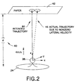
- drops such as drop 38 are emitted from printhead emitter 10, which travel typically approximately 1mm in a vertical direction 40 to print medium 42, usually paper.
- Fig. 2 illustrates that forces in the x,y,z axises act on drop 38, and any small initial lateral velocity of drop 38, as it leaves the ink surface 24, results in the drop being misplaced at the print medium 42.
- drops are emitted with a vertical velocity of 4m/s, and ideally no lateral velocity, resulting in the intended trajectory 44.
- Such misdirectionality may be due to a large number of causes including, static tilting of the ink surface, i.e. deformed meniscus, capillary waves on the surface of the ink, misalignment of the acoustic transducer with the lens, nonidealities in the lens or transducer, etc.
- Misplacement of drops on the medium may also occur if the drop is emitted at a location displaced from the middle of the acoustic lens, even if there is no lateral emission velocity. Such displacements however are rarely more than a few microns, and the great majority of objectionable drop misplacement at the paper surface is due to nonzero lateral velocity of the drop upon emission.
- the present invention discloses a method and apparatus which uses electric fields to focus drops having nonzero lateral velocity onto their intended locations at paper surface 42.
- the method and apparatus requires applied voltages as low as tens of volts, and does not involve inducing net charge on the drops. It makes use of the high dielectric constant of aqueous inks, and the force that a dielectric feels in a nonuniform electric field.
- the present inventors have considered to focus the drop 38 by using two successive dipole fields 48, 50.
- the first dipole field 48 focusses the drop along the x-axis, while defocusing along the y-axis.
- the second dipole field 50 which is orthogonal to the first, reverses the sense of the focussing. Travel of drop 38 through these fields has a net effect of focusing the trajectory to the desired location, independent of initial lateral velocity.
- Fig. 3 is a representation used to introduce the electric fields required for the present invention. It is to be appreciated different configurations can also be used to achieve the desired results.
- the wires produce dipole fields.
- the lower set of wires 48a, 48b produce an electric field whose magnitude increases away from the origin in the y-direction and is maximum at the origin along the x-direction.
- the upper two wires 50a, 50b produce an effect orthogonal to this.
- drop 38 is focussed in the x-direction as it moves between the lower two wires 48a, 48b, and is focussed in the y-direction as it moves between the upper two wires 50a, 50b.
- the electric field for lower wires 48a, 48b and upper wires 50a, 50b being generated by application of selected voltages from voltage source 51.
- Drop 38 has initial velocities, vx0, vy0, and vz0. Typically, vz0 4m/s.
- ⁇ represents a generally normalized charge density of two wires, i.e. normalized charge density ⁇ 1 and ⁇ 2 .
- ⁇ represents a generally normalized charge density of two wires, i.e. normalized charge density ⁇ 1 and ⁇ 2 .
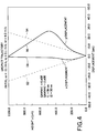
- a typical trajectory is shown in Fig. 4.
- the x-displacement and y-displacement of drop 38 are shown as a function of height z.
- the dotted lines 52 , 54 indicate the uncorrected trajectory, while the solid lines 56, 58 show the trajectory in the presence of the electric fields generated by 48, 50 of Fig. 3.
- the values of ⁇ 1 and ⁇ 2 are respectively 6.0 x 10 8 s -2 and 2.0 x 10 8 s -2.
- the values of t1 and t2 are 84 ⁇ s and 93 ⁇ s, respectively.
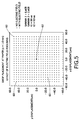
- the parameters ⁇ 1, ⁇ 2, t1, and t2 are those given above.
- Dots 60 are all those other than designated as 62. It is to be appreciated that for a printer of 600spi this is equal to an area of approximately 42.3 ⁇ m.
- the present invention can also be used with printers having other spots per inch values.
- the dots 64 representing a ink drop with a corrected trajectory and remaining dots 66 , representing ink drops with uncorrected trajectories. It is to be noted that there are various combinations of parameters which produce improved focusing, and it will be desirable to choose a specific set depending upon the physical restrictions of a given printhead geometry. Dots 64 are all those other than designated as 66 .
- the parameter ⁇ may be associated with voltages ⁇ V on a pair of parallel wires.
- the wires are then taken to have a radius b, and to be separated by a distance 2a.
- ⁇ 1000 kg/m 3
- Fig. 7a the wires are fabricated as upper fins 68a, 68b and lower fins 70a, 70b , whose cross section is indicated in Fig. 7b. It is valuable to note that there is in fact an ideal fin shape, which could readily be made by existing plating or micro machining techniques. This fin shape will produce exactly the desired field in the region between the fins, with minimum voltage applied to the fins.
- V 1 ⁇ ⁇ 2 ⁇ 1 2 x ⁇ 2 + 1 3 x 2 - y 2
- a fin is constructed with the appropriate profile to satisfy the voltage condition along its surface.
- Another approach to producing the desired fields would be to have each of the fins 74a-74d present, as described in Fig. 9, over the entire region 0 ⁇ z ⁇ d1 + d2 . Now, the appropriate fields are produced by applying the voltages temporally, at the appropriate time.
- the voltage V1 would be applied to one pair of fins 74a, 74b, while for time t1 ⁇ t ⁇ t1+t2 , the voltage V2 would be applied to the orthogonal pair of fins 74c, 74d .
- This approach allows a simple mechanical structure, at the cost of some complexity in driving the voltages, since they must be synchronized to the drop formation.
- the fin structure may be built on the existing aperture plate, or may be incorporated into the aperture shape itself.
- a single pair of helical fins may be used to produce ink droplet focusing as well. It should be understood the preceding describes the use of electric fields to reduce misdirectionality, due to the force on the dielectric drop in an electric field gradient. A number of structural embodiments may exist beyond those described here, for example, it is certainly possible to have more than two stages of alternating electrode fields along the trajectory of the drop.
- the pairs of wires or fins may be driven with a high-frequency AC voltage power supply (i.e. at a frequency much larger than 1/t1, 1/t2). This is important if there is inadvertently any net charge on the drop, for example as a result of its formation process. A net charge would otherwise introduce forces not included into the above analysis, most likely causing defocusing of the drop trajectories. The AC field would cause these forces to have a time-averaged value of zero. In addition, use of an AC voltage might be advantageous in minimizing electrochemical degradation of the structures overtime. It is to be appreciated that while primarily described in conjunction with AIP, the present invention can be used in other embodiments including the generation of a textured material and the generation on metal drops.
Landscapes
- Particle Formation And Scattering Control In Inkjet Printers (AREA)
- Liquid Deposition Of Substances Of Which Semiconductor Devices Are Composed (AREA)
Applications Claiming Priority (2)
| Application Number | Priority Date | Filing Date | Title |
|---|---|---|---|
| US98763 | 1998-06-17 | ||
| US09/098,763 US6312104B1 (en) | 1998-06-17 | 1998-06-17 | Reduction of spot misplacement through electrostatic focusing of uncharged drops |
Publications (2)
| Publication Number | Publication Date |
|---|---|
| EP0965450A1 true EP0965450A1 (fr) | 1999-12-22 |
| EP0965450B1 EP0965450B1 (fr) | 2002-04-10 |
Family
ID=22270779
Family Applications (1)
| Application Number | Title | Priority Date | Filing Date |
|---|---|---|---|
| EP99111677A Expired - Lifetime EP0965450B1 (fr) | 1998-06-17 | 1999-06-16 | Réduction des défauts de placement de points par la focalisation électrostatique de gouttelettes non chargées |
Country Status (5)
| Country | Link |
|---|---|
| US (1) | US6312104B1 (fr) |
| EP (1) | EP0965450B1 (fr) |
| JP (1) | JP4451511B2 (fr) |
| CA (1) | CA2271608C (fr) |
| DE (1) | DE69901205T2 (fr) |
Cited By (3)
| Publication number | Priority date | Publication date | Assignee | Title |
|---|---|---|---|---|
| US6367909B1 (en) | 1999-11-23 | 2002-04-09 | Xerox Corporation | Method and apparatus for reducing drop placement error in printers |
| WO2004063029A3 (fr) * | 2003-01-09 | 2004-11-18 | Picoliter Inc | Distribution de gouttelettes a partir d'un reservoir avec reduction dans la charge electrostatique non controlee |
| US7070260B2 (en) | 2003-01-09 | 2006-07-04 | Labcyte Inc. | Droplet dispensation from a reservoir with reduction in uncontrolled electrostatic charge |
Families Citing this family (4)
| Publication number | Priority date | Publication date | Assignee | Title |
|---|---|---|---|---|
| WO2009073862A1 (fr) * | 2007-12-07 | 2009-06-11 | Sunprint Inc. | Impression acoustique focalisée de matières photovoltaïques orientées |
| US20100184244A1 (en) * | 2009-01-20 | 2010-07-22 | SunPrint, Inc. | Systems and methods for depositing patterned materials for solar panel production |
| WO2015156820A1 (fr) * | 2014-04-11 | 2015-10-15 | Hewlett-Packard Development Company, L. P. | Génération d'un champ électrique non-uniforme pour maintenir des pigments dans un véhicule d'encre de fluide d'impression dans une région de buse de tête d'impression |
| FR3034426B1 (fr) * | 2015-03-31 | 2017-05-05 | Dover Europe Sarl | Composition d'encre pigmentaire, pour l'impression par jet continu devie binaire, a gouttes non chargees, de substrats en textile, procede de marquage, et substrat en textile ainsi marque |
Citations (3)
| Publication number | Priority date | Publication date | Assignee | Title |
|---|---|---|---|---|
| EP0608879A1 (fr) * | 1993-01-29 | 1994-08-03 | Canon Kabushiki Kaisha | Appareil à jet d'encre |
| WO1995032864A1 (fr) * | 1994-05-26 | 1995-12-07 | Tonejet Corporation Pty. Ltd. | Procede et dispositif permettant le transfert d'un materiau a partir d'une substance de base |
| EP0704304A1 (fr) * | 1994-09-30 | 1996-04-03 | Xerox Corporation | Varactor intégré et dispositif piézo-électrique pour l'impression d'encre acoustique |
Family Cites Families (9)
| Publication number | Priority date | Publication date | Assignee | Title |
|---|---|---|---|---|
| US4338613A (en) * | 1980-12-19 | 1982-07-06 | Pitney Bowes Inc. | Ink drop deflector |
| US4386358A (en) | 1981-09-22 | 1983-05-31 | Xerox Corporation | Ink jet printing using electrostatic deflection |
| US4379301A (en) | 1981-09-22 | 1983-04-05 | Xerox Corporation | Method for ink jet printing |
| US5122818A (en) | 1988-12-21 | 1992-06-16 | Xerox Corporation | Acoustic ink printers having reduced focusing sensitivity |
| US5087931A (en) | 1990-05-15 | 1992-02-11 | Xerox Corporation | Pressure-equalized ink transport system for acoustic ink printers |
| CA2049454C (fr) * | 1990-10-18 | 1999-01-05 | Michael E. Stamer | Dispositif de reglage automatique de la hauteur des caracteres pour imprimante a jet |
| US5392064A (en) | 1991-12-19 | 1995-02-21 | Xerox Corporation | Liquid level control structure |
| US5191354A (en) | 1992-02-19 | 1993-03-02 | Xerox Corporation | Method and apparatus for suppressing capillary waves in an ink jet printer |
| DE69610863T2 (de) * | 1995-02-21 | 2001-06-07 | K.K. Toshiba, Kawasaki | Tintenstrahldrucker |
-
1998
- 1998-06-17 US US09/098,763 patent/US6312104B1/en not_active Expired - Lifetime
-
1999
- 1999-05-13 CA CA002271608A patent/CA2271608C/fr not_active Expired - Fee Related
- 1999-06-14 JP JP16719699A patent/JP4451511B2/ja not_active Expired - Fee Related
- 1999-06-16 EP EP99111677A patent/EP0965450B1/fr not_active Expired - Lifetime
- 1999-06-16 DE DE69901205T patent/DE69901205T2/de not_active Expired - Lifetime
Patent Citations (3)
| Publication number | Priority date | Publication date | Assignee | Title |
|---|---|---|---|---|
| EP0608879A1 (fr) * | 1993-01-29 | 1994-08-03 | Canon Kabushiki Kaisha | Appareil à jet d'encre |
| WO1995032864A1 (fr) * | 1994-05-26 | 1995-12-07 | Tonejet Corporation Pty. Ltd. | Procede et dispositif permettant le transfert d'un materiau a partir d'une substance de base |
| EP0704304A1 (fr) * | 1994-09-30 | 1996-04-03 | Xerox Corporation | Varactor intégré et dispositif piézo-électrique pour l'impression d'encre acoustique |
Cited By (5)
| Publication number | Priority date | Publication date | Assignee | Title |
|---|---|---|---|---|
| US6367909B1 (en) | 1999-11-23 | 2002-04-09 | Xerox Corporation | Method and apparatus for reducing drop placement error in printers |
| WO2004063029A3 (fr) * | 2003-01-09 | 2004-11-18 | Picoliter Inc | Distribution de gouttelettes a partir d'un reservoir avec reduction dans la charge electrostatique non controlee |
| US7070260B2 (en) | 2003-01-09 | 2006-07-04 | Labcyte Inc. | Droplet dispensation from a reservoir with reduction in uncontrolled electrostatic charge |
| US7185969B2 (en) | 2003-01-09 | 2007-03-06 | Labcyte Inc. | Droplet dispensation from a reservoir with reduction in uncontrolled electrostatic charge |
| US7481511B2 (en) | 2003-01-09 | 2009-01-27 | Picoliter Inc. | Droplet dispensation from a reservoir with reduction in uncontrolled electrostatic charge |
Also Published As
| Publication number | Publication date |
|---|---|
| CA2271608C (fr) | 2003-04-29 |
| JP4451511B2 (ja) | 2010-04-14 |
| DE69901205D1 (de) | 2002-05-16 |
| JP2000006391A (ja) | 2000-01-11 |
| CA2271608A1 (fr) | 1999-12-17 |
| US6312104B1 (en) | 2001-11-06 |
| DE69901205T2 (de) | 2002-08-08 |
| EP0965450B1 (fr) | 2002-04-10 |
Similar Documents
| Publication | Publication Date | Title |
|---|---|---|
| CN104203582B (zh) | 静电打印机中的打印方法 | |
| JP4919435B2 (ja) | 差別的インクジェット偏向によるプリント | |
| US5975683A (en) | Electric-field manipulation of ejected ink drops in printing | |
| EP0911167A2 (fr) | Système d'impression continue à jet d'encre avec déviation binaire électrostatique | |
| US8840229B2 (en) | Continuous inkjet printing system and method for producing selective deflection of droplets formed from two different break off lengths | |
| JP2002210981A (ja) | 増幅された非対称加熱小滴偏向量を有するインクジェット装置 | |
| JP4130715B2 (ja) | 可変接触のインク粒子偏向による連続式インクジェットプリンタ | |
| US5963235A (en) | Continuous ink jet printer with micromechanical actuator drop deflection | |
| JPH05246035A (ja) | 液体噴射方法と、この方法を用いた連続インクジェットプリンターを有する高解像度印刷装置 | |
| JP2008540118A (ja) | 高速液体パターン塗布装置 | |
| EP0965450B1 (fr) | Réduction des défauts de placement de points par la focalisation électrostatique de gouttelettes non chargées | |
| EP1112847B1 (fr) | Système d'impression continue à jet d'encre muni d'un déflecteur avec encoche | |
| EP2828084B1 (fr) | Réduction d'erreur de disposition de gouttes dans une imprimante électrostatique | |
| JP4212273B2 (ja) | インク液滴偏向機構およびインク液滴の分岐の拡大方法 | |
| EP0832742B1 (fr) | Procédé de formation et de déplacement de gouttes d'encre | |
| US6367909B1 (en) | Method and apparatus for reducing drop placement error in printers | |
| US8646882B2 (en) | Drop placement error reduction in electrostatic printer | |
| US10308013B1 (en) | Controlling waveforms to reduce cross-talk between inkjet nozzles | |
| US4633268A (en) | Ink jet printer | |
| JP2651190B2 (ja) | 液体噴射記録方法 | |
| JPS60149469A (ja) | 液体噴射記録装置 |
Legal Events
| Date | Code | Title | Description |
|---|---|---|---|
| PUAI | Public reference made under article 153(3) epc to a published international application that has entered the european phase |
Free format text: ORIGINAL CODE: 0009012 |
|
| AK | Designated contracting states |
Kind code of ref document: A1 Designated state(s): DE FR GB |
|
| AX | Request for extension of the european patent |
Free format text: AL;LT;LV;MK;RO;SI |
|
| 17P | Request for examination filed |
Effective date: 20000623 |
|
| AKX | Designation fees paid |
Free format text: DE FR GB |
|
| 17Q | First examination report despatched |
Effective date: 20000926 |
|
| GRAG | Despatch of communication of intention to grant |
Free format text: ORIGINAL CODE: EPIDOS AGRA |
|
| GRAG | Despatch of communication of intention to grant |
Free format text: ORIGINAL CODE: EPIDOS AGRA |
|
| GRAH | Despatch of communication of intention to grant a patent |
Free format text: ORIGINAL CODE: EPIDOS IGRA |
|
| REG | Reference to a national code |
Ref country code: GB Ref legal event code: IF02 |
|
| GRAH | Despatch of communication of intention to grant a patent |
Free format text: ORIGINAL CODE: EPIDOS IGRA |
|
| GRAA | (expected) grant |
Free format text: ORIGINAL CODE: 0009210 |
|
| AK | Designated contracting states |
Kind code of ref document: B1 Designated state(s): DE FR GB |
|
| REF | Corresponds to: |
Ref document number: 69901205 Country of ref document: DE Date of ref document: 20020516 |
|
| ET | Fr: translation filed | ||
| PLBE | No opposition filed within time limit |
Free format text: ORIGINAL CODE: 0009261 |
|
| STAA | Information on the status of an ep patent application or granted ep patent |
Free format text: STATUS: NO OPPOSITION FILED WITHIN TIME LIMIT |
|
| 26N | No opposition filed |
Effective date: 20030113 |
|
| REG | Reference to a national code |
Ref country code: FR Ref legal event code: PLFP Year of fee payment: 18 |
|
| REG | Reference to a national code |
Ref country code: FR Ref legal event code: PLFP Year of fee payment: 19 |
|
| PGFP | Annual fee paid to national office [announced via postgrant information from national office to epo] |
Ref country code: FR Payment date: 20170523 Year of fee payment: 19 Ref country code: GB Payment date: 20170526 Year of fee payment: 19 Ref country code: DE Payment date: 20170522 Year of fee payment: 19 |
|
| REG | Reference to a national code |
Ref country code: DE Ref legal event code: R119 Ref document number: 69901205 Country of ref document: DE |
|
| GBPC | Gb: european patent ceased through non-payment of renewal fee |
Effective date: 20180616 |
|
| PG25 | Lapsed in a contracting state [announced via postgrant information from national office to epo] |
Ref country code: GB Free format text: LAPSE BECAUSE OF NON-PAYMENT OF DUE FEES Effective date: 20180616 Ref country code: FR Free format text: LAPSE BECAUSE OF NON-PAYMENT OF DUE FEES Effective date: 20180630 Ref country code: DE Free format text: LAPSE BECAUSE OF NON-PAYMENT OF DUE FEES Effective date: 20190101 |