EP0964977B1 - Improved auger cleaners - Google Patents
Improved auger cleaners Download PDFInfo
- Publication number
- EP0964977B1 EP0964977B1 EP98962616A EP98962616A EP0964977B1 EP 0964977 B1 EP0964977 B1 EP 0964977B1 EP 98962616 A EP98962616 A EP 98962616A EP 98962616 A EP98962616 A EP 98962616A EP 0964977 B1 EP0964977 B1 EP 0964977B1
- Authority
- EP
- European Patent Office
- Prior art keywords
- tool
- auger
- projecting elements
- flights
- radially projecting
- Prior art date
- Legal status (The legal status is an assumption and is not a legal conclusion. Google has not performed a legal analysis and makes no representation as to the accuracy of the status listed.)
- Expired - Lifetime
Links
- 230000010006 flight Effects 0.000 claims description 26
- 238000000605 extraction Methods 0.000 claims description 2
- 230000037431 insertion Effects 0.000 claims 1
- 238000003780 insertion Methods 0.000 claims 1
- 239000002689 soil Substances 0.000 description 18
- 238000004140 cleaning Methods 0.000 description 8
- 230000033001 locomotion Effects 0.000 description 3
- 238000000034 method Methods 0.000 description 2
- 238000007790 scraping Methods 0.000 description 2
- 208000027418 Wounds and injury Diseases 0.000 description 1
- 230000015572 biosynthetic process Effects 0.000 description 1
- 230000006378 damage Effects 0.000 description 1
- 230000001419 dependent effect Effects 0.000 description 1
- 230000000694 effects Effects 0.000 description 1
- 239000011440 grout Substances 0.000 description 1
- 238000011065 in-situ storage Methods 0.000 description 1
- 208000014674 injury Diseases 0.000 description 1
- 230000035515 penetration Effects 0.000 description 1
- 238000010008 shearing Methods 0.000 description 1
- 230000001360 synchronised effect Effects 0.000 description 1
- XLYOFNOQVPJJNP-UHFFFAOYSA-N water Substances O XLYOFNOQVPJJNP-UHFFFAOYSA-N 0.000 description 1
Images


Classifications
-
- E—FIXED CONSTRUCTIONS
- E21—EARTH OR ROCK DRILLING; MINING
- E21B—EARTH OR ROCK DRILLING; OBTAINING OIL, GAS, WATER, SOLUBLE OR MELTABLE MATERIALS OR A SLURRY OF MINERALS FROM WELLS
- E21B12/00—Accessories for drilling tools
- E21B12/06—Mechanical cleaning devices
Definitions
- the present invention relates to tools for cleaning an auger, in particular but not exclusively a continuous flight auger, as it is being withdrawn or after it has been withdrawn from the ground.
- a continuous flight auger comprises a generally cylindrical elongate body provided with a generally helical blade. Each 360° turn of the auger defines a flight of the blade, i.e. a flight is the space between adjacent, longitudinally-spaced sections of the blade.
- the auger is rotated into the ground to a predetermined depth at which the downward advance of the auger is halted.
- the auger may then be withdrawn without further rotation, thereby shearing a "plug" of soil directly from the ground so as to form a bore hole, or the auger may be rotated before withdrawal so as to shear the soil on the flights from the soil which will eventually form the wall of the resultant bore hole.
- concrete or grout may be pumped through the auger or down a feed pipe under positive pressure so as to form a cast-in-situ pile.
- augers have been cleaned by hand, for example by using a scraping implement and sometimes water jets. This, however, is labour intensive and can be dangerous.
- FR2594481 discloses an auger cleaning tool having a stem and a helically shaped element disposed about the stem. In use, the tool is applied to a section of the region of the auger between adjacent flights, the tool stem extending in a direction substantially parallel thereto.
- a tool for removing debris from flights of a blade of an auger or other screw-conveyor comprising a central shaft about which is helically arranged a plurality of radially projecting elements, characterised in that said projecting elements are disposed at intervals about said stem so as to trace a helical path.
- the tool is mounted adjacent to an auger, with the central shaft being substantially parallel to the auger stem.
- the tool is mounted in such a way that it can be moved near to and away from the auger in such a way that the projecting elements may be gradually introduced to the auger flights. Cleaning the auger in this manner is assisted by way of soil being packed more loosely between the flights at the top of the auger than between those at the bottom.
- the radially projecting elements are arranged in a helix which has substantially the same pitch as that of the auger blade. As the auger is withdrawn from the ground, the tool is brought up to the auger and rotated so that the projecting elements engage with the auger flights.
- the rate and direction of rotation is dependent on the rate of withdrawal of the auger and whether or not the auger is also being rotated.
- the projecting elements are disposed in a helix having the opposite sense to that of the auger blade, then the tool must be rotated in the opposite direction to the auger so as to counter flight movement.
- the projecting elements may be disposed in a helix having the same sense as that of the auger blade, in which case the tool is rotated in the same direction as the auger.
- the former arrangement may be advantageous in that the angle of attack of the projecting elements on the flights of the auger is increased, and any locked-in soil will tend to be pushed downwards.
- the auger may, for example, be repeatedly turned forwards by half a turn and then backwards by half a turn, with the tool rotating accordingly.
- a particular advantage of the present invention is that it can be used in applications where an auger is rotated relatively slowly during withdrawal. This is because the projecting elements simultaneously penetrate adjacent flights of the auger. Furthermore, since rotation of the tool allows continuous parallel movement between the tool and the auger, the tool does not need to be separated from and repositioned on the auger as it is withdrawn. This helps to ensure that no sections along the length of the auger are missed.
- two, three or more tools may be disposed substantially equiangularly about the auger so as to attack soil on the auger flights from a number of directions simultaneously. Such an arrangement, particularly with three tools, also means that any lateral forces which may tend to push a single tool and the auger away from each other may be balanced out.
- the tool may be rotated by way of a mechanical linkage which couples the tool to the auger drive means.
- a linkage which may take the form of a bushing or other driving arrangement, automatically synchronises the rotations of the tool and the auger so as to prevent relative fouling.
- the tool may be rotated by way of an independent electric or hydraulic motor.
- sensors are provided which detect the proximity of the auger flights to the tool.
- appropriate rotation of the tool is commanded so as to bring the projecting elements back to the mid-point of each flight.
- On-board instrumentation and computer means may be provided so as to allow complete control of the tool. For example, given the angle of rotation of the auger, the depth change and the pitch of the auger blade, it is possible to calculate and apply the correct rate of rotation to the tool so as to ensure synchronisation with the auger.
- the radially projecting elements may take the form of blades, cutting tools, digging tools, brushes and any combination thereof. It is generally preferred to include at least one blade or cutting tool, since soil removal is facilitated by cutting a groove into the locked-in soil so as to allow the same to swell and hence to fall away from the auger.
- the radial extension of at least some of the projecting elements should be at least as great as the radius of the largest auger with which the tool is to be used. This is to ensure that the flights are cleaned thoroughly.
- the envelope defining the radial extension of the projecting elements may be selected to start from the diameter of the central shaft at the lower end of the tool and gradually to increase along the length of the tool until full penetration of the auger flights is achieved.
- a further feature is that different projecting elements may be arranged along the length of the tool so as to facilitate the removal of different conditions of soil, for example loosely- or densely-packed.
- brushes can be arranged at the top of the tool so as to complete the auger cleaning operation.
- the projecting elements need not be permanently attached to the central shaft of the tool, but may be readily interchanged so as to allow the tool to be tailored to specific applications.
- Figure 1 shows an auger 1 having a blade 2.
- a tool 3, comprising a central shaft 4 on which are removably mounted a number of flat blades 5 in a helical formation, engages with the blade 2 of the auger 1.
- the pitch of the blades 5 is substantially the same as the pitch of the auger blade 2, and the sense of the helical arrangement of the blades 5 is opposite to that of the blade 2.
- the tool 3 has a length of around 1 to 2m, and the auger 1 has a length of up to 20m.
- the auger 1 is rotated so as to counter the movement of the blade 2 of the auger 1.
- Rotation of the tool 3 is synchronised with rotation of the auger 1 so that the blades 5 penetrate adjacent flights 6, 6' without fouling the blade 2 itself. In this way, any soil (not shown) locked into the flights 6, 6' of the auger 1 is effectively removed.
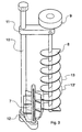
- FIG. 2 and 3 An alternative arrangement is shown in Figures 2 and 3, where an auger cleaning tool 7 is pivotably mounted next to an auger 8.
- the auger 8 is rotated by way of a drive head 9 mounted at the top of the auger 8.
- the drive head also serves to rotate the tool 7 in the appropriate direction by way of a shaft 10 and mechanical linkages 11 and 12.
- the tool 7 may be swung away from the auger 8 so that it no longer engages with the flights 13, 13' of the auger, thereby allowing the drive head 9 to pass by most of the body of the tool 7 and thereby enabling the auger to penetrate the ground to a deeper level than would otherwise be the case.
Landscapes
- Engineering & Computer Science (AREA)
- Life Sciences & Earth Sciences (AREA)
- Geology (AREA)
- Mining & Mineral Resources (AREA)
- Mechanical Engineering (AREA)
- Physics & Mathematics (AREA)
- Environmental & Geological Engineering (AREA)
- Fluid Mechanics (AREA)
- General Life Sciences & Earth Sciences (AREA)
- Geochemistry & Mineralogy (AREA)
- Earth Drilling (AREA)
- Harvesting Machines For Root Crops (AREA)
Description
Claims (10)
- A tool (3) for removing debris from flights of a blade (2) of an auger (1) or other screw-conveyor, the tool comprising a central shaft (4) about which is helically arranged a plurality of radially projecting elements (5), characterised in that said projecting elements are disposed at intervals about said stem so as to trace a helical path.
- A tool as claimed in claim 1, wherein the radially projecting elements (5) comprise blades, cutting tools, digging tools or any combination thereof.
- A tool as claimed in claim 1 or 2, wherein the radially projecting elements (5) comprise brushes.
- A tool as claimed in claim 1, 2 or 3, wherein the radially projecting elements (5) are detachably mounted on the central shaft (4).
- A tool as claimed in any preceding claim, wherein the radial extension of the radially projecting elements (5) increases along at least a portion of the length of the tool (3) from bottom to top.
- A tool as claimed in any preceding claim, wherein the tool, in use, is rotatably mounted adjacent the auger (1) such that at least some of the radially projecting elements (5) penetrate at least some of the flights of the auger.
- A tool as claimed in claim 6, wherein the tool, in use, is mounted so that it may be moved near to and away from the auger in such a way that the radially projecting elements (5) may be gradually introduced into the flights of the auger (1).
- A tool as claimed in claim 7, wherein the tool may be moved away from the auger so as to allow the auger (1) to bypass at least part of the tool (3) during insertion and extraction.
- A tool as claimed in claim 6, 7 or 8, wherein the tool (3) is mechanically coupled to drive means adapted to rotate the auger (1), such that the tool is rotated in synchronism with the auger.
- A tool as claimed in claim 6, 7 or 8, wherein the tool (3) is provided with separate rotational drive means (9) and with sensors which detect the proximity of the radially projecting elements to the blade of the auger, a feedback control mechanism being provided between the drive means and the sensors which controls the rotation of the tool so as to tend to pass the projecting elements between adjacent flights without fouling the blade.
Applications Claiming Priority (3)
| Application Number | Priority Date | Filing Date | Title |
|---|---|---|---|
| GB9727273A GB2332689B (en) | 1997-12-24 | 1997-12-24 | Improved auger cleaners |
| GB9727273 | 1997-12-24 | ||
| PCT/GB1998/003891 WO1999034086A1 (en) | 1997-12-24 | 1998-12-23 | Improved auger cleaners |
Publications (2)
| Publication Number | Publication Date |
|---|---|
| EP0964977A1 EP0964977A1 (en) | 1999-12-22 |
| EP0964977B1 true EP0964977B1 (en) | 2004-03-10 |
Family
ID=10824186
Family Applications (1)
| Application Number | Title | Priority Date | Filing Date |
|---|---|---|---|
| EP98962616A Expired - Lifetime EP0964977B1 (en) | 1997-12-24 | 1998-12-23 | Improved auger cleaners |
Country Status (8)
| Country | Link |
|---|---|
| US (1) | US6189681B1 (en) |
| EP (1) | EP0964977B1 (en) |
| AU (1) | AU1774599A (en) |
| CA (1) | CA2281759C (en) |
| DE (1) | DE69822290T2 (en) |
| ES (1) | ES2215335T3 (en) |
| GB (1) | GB2332689B (en) |
| WO (1) | WO1999034086A1 (en) |
Cited By (2)
| Publication number | Priority date | Publication date | Assignee | Title |
|---|---|---|---|---|
| DE102012006306A1 (en) * | 2012-03-21 | 2013-09-26 | Liebherr-Werk Nenzing Gmbh | Cleaning apparatus used for cleaning auger of drilling excavator, has cleaning device that is set outside the thread portion of auger in original position and is extended up in thread portion of auger in cleaning position |
| KR102178545B1 (en) * | 2019-07-05 | 2020-11-13 | 윤춘호 | Removal Device of Earth and Sand Attached Screw of Upper Auger |
Families Citing this family (12)
| Publication number | Priority date | Publication date | Assignee | Title |
|---|---|---|---|---|
| DE19941409C1 (en) * | 1999-08-31 | 2001-02-15 | Bauer Spezialtiefbau | Screw cleaner for helical drilling tool has 2 offset cleaning elements pivoted relative to common holder into and out of engagement with helical screw thread of drilling tool via drive unit |
| GB0019804D0 (en) * | 2000-08-12 | 2000-09-27 | Elle Holdings Limited Van | Auger cleaning device |
| US6601692B2 (en) * | 2001-07-13 | 2003-08-05 | Schaefer Brush Manufacturing | Device for cleaning endless conveyors |
| GB2414998B (en) * | 2004-06-10 | 2008-04-16 | Cementation Found Skanska Ltd | Auger cleaner |
| US6964331B1 (en) * | 2004-07-06 | 2005-11-15 | Material Control, Inc. | Cantilever mounted rotary brush conveyor belt cleaner |
| CN103161407A (en) * | 2013-03-28 | 2013-06-19 | 洛阳舒诚机械设备有限公司 | Soil pushing device special for spiral |
| CN105089512A (en) * | 2014-05-12 | 2015-11-25 | 湖南泰达天易重工有限公司 | Under-slung auger stem desilting machine |
| CN104528331B (en) * | 2014-12-12 | 2017-09-01 | 中冶南方工程技术有限公司 | A kind of blade cleaning equipment of spiral conveying mechanism |
| US10024115B1 (en) | 2017-07-11 | 2018-07-17 | Jimmy Bollman | Auger cleaning apparatus |
| KR101939498B1 (en) * | 2017-10-18 | 2019-01-16 | 나춘식 | Removing foreign substances device of Screw for drilling machine |
| DE102019109012A1 (en) * | 2019-04-05 | 2020-10-08 | Marcus Burg | Cleaning device |
| CN113058913A (en) * | 2021-03-25 | 2021-07-02 | 四川安和昌盛科技有限公司 | Maintenance method of milling cutter |
Family Cites Families (13)
| Publication number | Priority date | Publication date | Assignee | Title |
|---|---|---|---|---|
| US165228A (en) * | 1875-07-06 | Improvement in driers | ||
| US1602375A (en) | 1925-05-02 | 1926-10-05 | Leo E Gibson | Earth-boring mechanism |
| US3540572A (en) * | 1967-12-07 | 1970-11-17 | Raymond Int Inc | Cleaning helical flights |
| US3782535A (en) * | 1972-06-15 | 1974-01-01 | T Yousch | Screw conveyor coil wiper |
| FR2563861B1 (en) | 1984-05-03 | 1986-08-29 | Soletanche | DEVICE FOR CLEANING AUGER BITS. |
| SU1253902A1 (en) * | 1985-04-04 | 1986-08-30 | Белгородский филиал Всесоюзного проектно-конструкторского технологического института атомного машиностроения и котлостроения | Screw conveyer |
| FR2594481A1 (en) | 1986-02-18 | 1987-08-21 | Bourg Claude | System for cleaning the augers used for a special foundation. |
| JPS6411629A (en) * | 1987-07-06 | 1989-01-17 | Daiki Kogyo Kk | Screw device |
| GB2235480A (en) | 1989-08-15 | 1991-03-06 | English Drilling Equipment Co | Improvements in or relating to the clearing of drills |
| IT1236315B (en) | 1989-11-21 | 1993-02-09 | SCRAPING DEVICE FOR CONTINUOUS PROPELLER DRILLS | |
| JPH05147721A (en) * | 1991-11-26 | 1993-06-15 | Kanebo Ltd | Screw conveyor cleaning device |
| US5242027A (en) * | 1992-03-09 | 1993-09-07 | Berkel & Company Contractors, Inc. | Cleaning device for earth augers |
| GB2265922A (en) * | 1992-04-01 | 1993-10-13 | Starlite Investment Ltd | Cleaning augers and screw-conveyors |
-
1997
- 1997-12-24 GB GB9727273A patent/GB2332689B/en not_active Expired - Lifetime
-
1998
- 1998-12-23 CA CA002281759A patent/CA2281759C/en not_active Expired - Fee Related
- 1998-12-23 ES ES98962616T patent/ES2215335T3/en not_active Expired - Lifetime
- 1998-12-23 WO PCT/GB1998/003891 patent/WO1999034086A1/en not_active Ceased
- 1998-12-23 US US09/367,937 patent/US6189681B1/en not_active Expired - Fee Related
- 1998-12-23 DE DE69822290T patent/DE69822290T2/en not_active Expired - Fee Related
- 1998-12-23 AU AU17745/99A patent/AU1774599A/en not_active Abandoned
- 1998-12-23 EP EP98962616A patent/EP0964977B1/en not_active Expired - Lifetime
Cited By (2)
| Publication number | Priority date | Publication date | Assignee | Title |
|---|---|---|---|---|
| DE102012006306A1 (en) * | 2012-03-21 | 2013-09-26 | Liebherr-Werk Nenzing Gmbh | Cleaning apparatus used for cleaning auger of drilling excavator, has cleaning device that is set outside the thread portion of auger in original position and is extended up in thread portion of auger in cleaning position |
| KR102178545B1 (en) * | 2019-07-05 | 2020-11-13 | 윤춘호 | Removal Device of Earth and Sand Attached Screw of Upper Auger |
Also Published As
| Publication number | Publication date |
|---|---|
| EP0964977A1 (en) | 1999-12-22 |
| DE69822290T2 (en) | 2004-07-29 |
| GB2332689B (en) | 2002-01-16 |
| GB9727273D0 (en) | 1998-02-25 |
| US6189681B1 (en) | 2001-02-20 |
| AU1774599A (en) | 1999-07-19 |
| ES2215335T3 (en) | 2004-10-01 |
| WO1999034086A1 (en) | 1999-07-08 |
| DE69822290D1 (en) | 2004-04-15 |
| GB2332689A (en) | 1999-06-30 |
| CA2281759C (en) | 2007-05-15 |
| CA2281759A1 (en) | 1999-07-08 |
Similar Documents
| Publication | Publication Date | Title |
|---|---|---|
| CA2281759C (en) | Improved auger cleaners | |
| CA2597819C (en) | Method and device for producing a borehole in the soil | |
| JP2013253455A (en) | First tube and underground obstacle removal method | |
| GB2158130A (en) | Apparatus for cleaning drills | |
| US8820435B2 (en) | Auger for digging holes | |
| EP0427454B1 (en) | Auger cleaner | |
| CN215948450U (en) | Drill bit for tunnel drainage blind pipe dredging equipment | |
| GB2265922A (en) | Cleaning augers and screw-conveyors | |
| JP3797793B2 (en) | Shield machine and shield method | |
| CN113153171B (en) | Automatic scraping method for slime in long-spiral drilling | |
| JP6435077B1 (en) | Drilling head | |
| SU817145A1 (en) | Borehole drilling unit | |
| JP5225309B2 (en) | Crushing head | |
| JP2628009B2 (en) | Cutting method of existing underground anchor material | |
| CN112664217A (en) | Tube push bench with rotatable blades | |
| JP3416936B2 (en) | Excavator and propulsion pipe | |
| JP7320477B2 (en) | MUST REMOVAL DEVICE AND MUST REMOVAL METHOD | |
| JP4984297B2 (en) | Excavation tool for underground anchor and method for removing underground anchor | |
| JP5607944B2 (en) | Drilling head | |
| EP0109485B1 (en) | Apparatus for improving ground | |
| JP2004044244A (en) | Roller cutter of underground excavator, spiral roller cutter, and cutter head equipped with the same | |
| JPH0533342A (en) | Device for removing existing concrete pile | |
| JP5042803B2 (en) | Updating apparatus and updating method for existing buried pipe | |
| GB2414998A (en) | Auger cleaner | |
| GB2235480A (en) | Improvements in or relating to the clearing of drills |
Legal Events
| Date | Code | Title | Description |
|---|---|---|---|
| PUAI | Public reference made under article 153(3) epc to a published international application that has entered the european phase |
Free format text: ORIGINAL CODE: 0009012 |
|
| 17P | Request for examination filed |
Effective date: 19990823 |
|
| AK | Designated contracting states |
Kind code of ref document: A1 Designated state(s): BE DE ES FR IT NL |
|
| RAP1 | Party data changed (applicant data changed or rights of an application transferred) |
Owner name: CEMENTATION FOUNDATIONS SKANSKA LIMITED |
|
| 17Q | First examination report despatched |
Effective date: 20021203 |
|
| GRAP | Despatch of communication of intention to grant a patent |
Free format text: ORIGINAL CODE: EPIDOSNIGR1 |
|
| GRAS | Grant fee paid |
Free format text: ORIGINAL CODE: EPIDOSNIGR3 |
|
| GRAA | (expected) grant |
Free format text: ORIGINAL CODE: 0009210 |
|
| AK | Designated contracting states |
Kind code of ref document: B1 Designated state(s): BE DE ES FR IT NL |
|
| REF | Corresponds to: |
Ref document number: 69822290 Country of ref document: DE Date of ref document: 20040415 Kind code of ref document: P |
|
| REG | Reference to a national code |
Ref country code: ES Ref legal event code: FG2A Ref document number: 2215335 Country of ref document: ES Kind code of ref document: T3 |
|
| ET | Fr: translation filed | ||
| PLBE | No opposition filed within time limit |
Free format text: ORIGINAL CODE: 0009261 |
|
| STAA | Information on the status of an ep patent application or granted ep patent |
Free format text: STATUS: NO OPPOSITION FILED WITHIN TIME LIMIT |
|
| 26N | No opposition filed |
Effective date: 20041213 |
|
| PGFP | Annual fee paid to national office [announced via postgrant information from national office to epo] |
Ref country code: ES Payment date: 20061127 Year of fee payment: 9 |
|
| PGFP | Annual fee paid to national office [announced via postgrant information from national office to epo] |
Ref country code: FR Payment date: 20061220 Year of fee payment: 9 |
|
| REG | Reference to a national code |
Ref country code: FR Ref legal event code: ST Effective date: 20081020 |
|
| REG | Reference to a national code |
Ref country code: ES Ref legal event code: FD2A Effective date: 20071224 |
|
| PGFP | Annual fee paid to national office [announced via postgrant information from national office to epo] |
Ref country code: BE Payment date: 20081208 Year of fee payment: 11 Ref country code: IT Payment date: 20081125 Year of fee payment: 11 |
|
| PG25 | Lapsed in a contracting state [announced via postgrant information from national office to epo] |
Ref country code: FR Free format text: LAPSE BECAUSE OF NON-PAYMENT OF DUE FEES Effective date: 20071231 Ref country code: ES Free format text: LAPSE BECAUSE OF NON-PAYMENT OF DUE FEES Effective date: 20071224 |
|
| PGFP | Annual fee paid to national office [announced via postgrant information from national office to epo] |
Ref country code: NL Payment date: 20081219 Year of fee payment: 11 Ref country code: DE Payment date: 20081222 Year of fee payment: 11 |
|
| BERE | Be: lapsed |
Owner name: *CEMENTATION FOUNDATIONS SKANSKA LTD Effective date: 20091231 |
|
| REG | Reference to a national code |
Ref country code: NL Ref legal event code: V1 Effective date: 20100701 |
|
| PG25 | Lapsed in a contracting state [announced via postgrant information from national office to epo] |
Ref country code: NL Free format text: LAPSE BECAUSE OF NON-PAYMENT OF DUE FEES Effective date: 20100701 Ref country code: BE Free format text: LAPSE BECAUSE OF NON-PAYMENT OF DUE FEES Effective date: 20091231 |
|
| PG25 | Lapsed in a contracting state [announced via postgrant information from national office to epo] |
Ref country code: DE Free format text: LAPSE BECAUSE OF NON-PAYMENT OF DUE FEES Effective date: 20100701 |
|
| PG25 | Lapsed in a contracting state [announced via postgrant information from national office to epo] |
Ref country code: IT Free format text: LAPSE BECAUSE OF NON-PAYMENT OF DUE FEES Effective date: 20091223 |