EP0964236A1 - Apparatus for inspecting container for leakage of liquid - Google Patents
Apparatus for inspecting container for leakage of liquid Download PDFInfo
- Publication number
- EP0964236A1 EP0964236A1 EP98961540A EP98961540A EP0964236A1 EP 0964236 A1 EP0964236 A1 EP 0964236A1 EP 98961540 A EP98961540 A EP 98961540A EP 98961540 A EP98961540 A EP 98961540A EP 0964236 A1 EP0964236 A1 EP 0964236A1
- Authority
- EP
- European Patent Office
- Prior art keywords
- container
- probe
- mouth portion
- unit
- conveyer
- Prior art date
- Legal status (The legal status is an assumption and is not a legal conclusion. Google has not performed a legal analysis and makes no representation as to the accuracy of the status listed.)
- Granted
Links
Images


Classifications
-
- G—PHYSICS
- G01—MEASURING; TESTING
- G01M—TESTING STATIC OR DYNAMIC BALANCE OF MACHINES OR STRUCTURES; TESTING OF STRUCTURES OR APPARATUS, NOT OTHERWISE PROVIDED FOR
- G01M3/00—Investigating fluid-tightness of structures
- G01M3/02—Investigating fluid-tightness of structures by using fluid or vacuum
- G01M3/04—Investigating fluid-tightness of structures by using fluid or vacuum by detecting the presence of fluid at the leakage point
- G01M3/16—Investigating fluid-tightness of structures by using fluid or vacuum by detecting the presence of fluid at the leakage point using electric detection means
- G01M3/18—Investigating fluid-tightness of structures by using fluid or vacuum by detecting the presence of fluid at the leakage point using electric detection means for pipes, cables or tubes; for pipe joints or seals; for valves; for welds; for containers, e.g. radiators
- G01M3/184—Investigating fluid-tightness of structures by using fluid or vacuum by detecting the presence of fluid at the leakage point using electric detection means for pipes, cables or tubes; for pipe joints or seals; for valves; for welds; for containers, e.g. radiators for valves
Abstract
Description
- The present invention relates to a liquid leakage inspecting device which inspects a barrel-like liquid container containing beer, for instance, and detects liquid leakage from the mouth of the container.
- Conventionally, a container for beer is barrel-shaped and made of an aluminum plate or steel plate. The barrel-shaped container is strong, and has a relatively large capacity. The capacity of such a container is 7 litters, 10 litters, 15 litters, 20 litters, 25 litters, or 50 litters. The container is provided with a sealing stopper unit in its mouth portion to maintain the quality of the content liquid sealed in the container, and to prevent the content liquid from deteriorating and loosing flavor.
- The sealing stopper unit comprises: a mouth portion 1a formed on the upper surface or the lower surface of a
container 1 containing liquid such as beer B; a bush a placed in the mouth portion 1a; a liquid raising cylindrical member c inserted into the bush a by the pushing force of first springs b; a gas valve d provided on the outer periphery of the upper surface of the liquid raising cylindrical member c so as to be engaged with the inner surface of the upper portion of the bush a; and a solution valve f which raises the content liquid by pressure air G supplied into thecontainer 1 through the liquid raising cylindrical member c when the gas valve d is opened by the pushing force of second springs e, and which valve f discharges the content liquid out of thecontainer 1. - In the production line of the beer B, defective products whose content liquid is leaking from the mouth portion 1a of the
container 1 are detected and then discharged out of the main line of the production line. Thecontainer 1 is repeatedly used in view of resource conservation. - In the liquid leakage inspecting device which judges whether the content liquid is leaking from the mouth portion 1a of the
container 1, pure water w is injected into a concave portion g formed on the upper surface of the sealing stopper unit 4' in the mouth portion 1a of thecontainer 1, and a probe P is then put in the pure water w to measure its electric conductivity, thereby detecting liquid leakage. - In Figs. 8 and 9, cylinders S'1 are disposed on both sides of a conveyer 2' which transports the
container 1 having the sealing stopper unit 4' in the mouth portion 1a. The rods of the cylinders S'1 are provided with clamp units 12' which can be opened and closed with respect to rotational axes 16'. The clamp units 12' are connected to holding frames 15' provided with rollers 14', and holds thecontainer 1 for liquid leakage inspection by a leakage inspecting unit 20'. In the next step to the clamp units 12' on the conveyer 2', cylinders S'2 provided on both sides of the conveyer 2' are actuated to extend the rods toward the axis center O of thecontainer 1. Stopper units 17' having contact portions are attached to the edges of the respective rods of the cylinders S'2. In the next step to the stopper units 17', a water supply unit 31' which supplies the pure water w into the concave portion g formed in the upper portion of the sealing stopper unit 4' is formed. In the next step to the water supply unit 31', a probe P and a leakage inspecting unit 20' are formed. The double-cylindrical probe P is inserted into the pure water w supplied into the concave portion g to measure the electric conductivity of the water, thereby judging whether the content liquid is leaking from the mouth portion 1a. The leakage inspecting unit 20' is provided with a water supply unit 31'' which rotates in the vertical direction by 90 degrees in the ascending position of the probe P after the measurement, and which water supply unit 31'' supplies wash water to wash the probe P. In the next step to the leakage inspecting unit 20', an air supply unit 43' which blows dry air or hot air to the water in the concave portion g is provided. In the next step to the air supply unit 43', a reject conveyer 45' is provided. The reject conveyer 43' transports thecontainer 1 judged to be a defective product having leakage and discharged out of the main line of the production line by actuating a reject cylinder S'6. - Positioning units 21' are formed in the locations of the water supply unit 31', the leakage inspecting unit 20', and the air supply unit 43'. Each of the positioning units 21' stops and positions the
container 1 being transported on the conveyer 2'. Cylinders S'3 and S'4 as driving power sources are provided on both sides of the conveyer 2'. The edge of each rod of the cylinders S'3 is provided with a grip unit 50' having an arcuate inner surface 50'a corresponding to the outerperipheral surface 1b of thecontainer 1. Each rod of the cylinders S'4 extends toward the axis center O of thecontainer 1, and is provided with a contact portion 24' (not shown) which can be in contact with the outerperipheral surface 1b of thecontainer 1. The conveyer 2' is a belt conveyer or a roller conveyer, for instance. - In a conventional liquid leakage inspecting unit shown in Fig. 8, pure water is injected into the concave portion g formed in the mouth portion g of the
container 1 being transported on the conveyer in the pure water injecting position. When thecontainer 1 being transported on the conveyer reaches the inspecting position, the probe P is inserted into the pure water in the concave portion g to measure the electric conductivity of the water. Here, the pure water injecting position is situated at a distance from the inspecting position. Because of this, the pure water injected into the concave portion g of the container in the pure water injection position is subjected to the vibration from the conveyer or the shock caused by thecontainer 1 brought into contact with the guide members. As a result, the pure water flows out of the concave portion, hindering accurate measure of the electric conductivity. - There is another problem that the electric conductivity can be measured only when the beer B is leaking into the pure water from the gas valve d or the solution valve f of the sealing stopper unit 4', because the probe P is inserted into the pure water w injected only into the concave portion g formed on the upper surface of the sealing stopper unit 4'.
- In other words, leakage from the boundary between the mouth portion 1a and the bush a cannot be detected.
- In the conventional liquid leakage inspecting device shown in Figs. 8 and 9, the probe P is rotated in the vertical direction by 90 degrees in its ascending position after the leakage detection by the probe P inserted into the pure water w supplied into the concave portion g of the mouth portion 1a from the water supply unit 31' of the leakage inspecting unit 20'. The water supply unit 31'' then supplies wash water to wash the probe P. After that, the air supply unit 43' provided in the next step to the leakage inspecting unit 20' blows dry air or hot air to dry the washed probe P.
- As described above, washing the probe P requires a rotating operation of the probe P. Also, since the air supply position is situated at a distance from the water supply position, the drying of the probe P adds to the number of procedures, resulting in poor efficiency of the liquid leakage inspection on the conveyer 2'.
- Furthermore, since the water supply unit 31'' supplies water only to the outer surface of the probe P, the inside of the double-cylindrical probe P cannot be sufficiently washed. As a result, dust and impurities remain in the probe P, thereby causing a problem that accurate leakage detection cannot be achieved with the repeatedly used probe P.
- In the conventional liquid leakage inspecting device shown in Fig. 8, the
container 1 being transported on the conveyer 2' is sandwiched by the rollers 14' in the clamp unit 12' when the cylinders S'1 as the driving power sources on both sides of the conveyer 2' are actuated. In the stopper unit 17', the contact portions 24' at the edges of the extended rods of the cylinders S'2 disposed on both sides of the conveyer 2' are brought into contact with the sides and the front of the outerperipheral surface 1b, thereby stopping the transportation of thecontainer 1. In the locations of the water supply unit 31', the leakage inspecting unit 20', and the air supply unit 43', each of the cylinders S'3 and S'4 disposed on both sides of the conveyer 2' is actuated so that thecontainer 1 is sandwiched by the contact portion 24' and the corresponding grip unit 50' having the arcuate inner surface 50'a. - The barrel-
shaped container 1 made of an aluminum plate or a steel plate is forcibly pressed at both sides by the cylinders S'1 to S'4 disposed on both sides of the conveyer 2', every time axis center matching, positioning, or transportation halting is performed on the conveyer 2'. As a result, the outer surface of thecontainer 1 is often damaged or deformed. If repeatedly used over a long period of time, thecontainer 1 is deformed during transportation or storing, resulting in irregularity in shape. - If the
container 1 is deformed, the nozzle of the water supply unit 31' is situated outside the concave portion g. In such a case, the pure water necessary for the inspection cannot be pooled sufficiently in the concave portion g. Also, the axis center O' of the probe P does not correspond to the axis center O of thecontainer 1 and is situated outside the concave portion g. As a result, the probe P cannot be inserted properly into the concave portion g, but the probe P might be brought into contact with the inner surface of the concave portion g instead. This causes errors in the leakage inspection, and containers might be wrongly judged to be defective products even when there is no leakage. With the above problems, accurate leakage detection cannot be expected. - If the containers vary in size, it is necessary to change the grip units 50' in accordance with the size of each container.
- The present invention provides a liquid leakage inspecting device which eliminates the above problems with the conventional liquid leakage inspecting device, such as the poor accuracy in the detection due to the insufficient amount of pure water, and the inability to detect leakage from the boundary between the mouth portion of the container and the bush. In the liquid leakage inspecting device of the present invention, the pure water injecting position corresponds to the inspecting position on the conveyer, and the pure water necessary for the inspection is supplied in the inspecting position. The pure water is prevented from flowing out during the transportation of the container, so that the electric conductivity can be measured with high accuracy. Accordingly, the liquid leakage inspection can be efficiently conducted. Also, liquid leakage from the boundary between the inner surface of the mouth portion of the container and the outer surface of the bush can be automatically and quickly detected. Moreover, the structure of the device of the present invention is simple, and the number of components is small. Thus, compared with the prior art, the production procedures can be simplified, and the production costs can be reduced.
- The present invention also provides a liquid leakage inspecting device which eliminates the problem with the drying and washing of the conventional probe, performs the washing and drying of the probe in a short time with little trouble, and efficiently conducts liquid leakage inspection with high accuracy.
- The present invention further provides a liquid leakage inspecting device which eliminates the problems with the prior art, such as the inaccurate inspection due to damage or deformation of the container, and inability to comply with different sizes of the container. In the liquid leakage inspecting device of the present invention, the container being transported on the conveyer can be prevented from being damaged or deformed, so that the container can be repeatedly used over a long period of time. The axis matching of the probe can be easily and accurately in accordance with the shape and size of the container, and the container can be easily and accurately positioned and stopped at a desired inspecting spot. The pure water for the leakage inspection can be sufficiently supplied into the concave portion, and the container can be prevented from being wrongly judged to be a defective product. Thus, the device of the present invention can perform highly accurate liquid leakage inspection.
- To eliminate the above problems, the present invention provides a leakage inspecting device which has a sealing stopper unit comprising: a bush attached to a mouth portion of a container containing liquid such as beer being transported on a conveyer; a liquid raising cylindrical member movably inserted into the bush in the vertical direction; a gas valve which can be opened and closed, is formed on the outer periphery of the upper surface of the liquid raising cylindrical member, and is engageable with the inner surface of the upper portion of the bush; and a solution valve which raises the content liquid through the liquid raising cylindrical member by supplying pressure air into the container when the gas valve is opened, and then discharges the content liquid out of the container, and which device measures the electric conductivity of water by inserting a probe into pure water supplied into a concave portion formed in the upper portion of the sealing stopper unit in the mouth portion of the container, thereby judging whether the content liquid is leaking. The leakage inspecting device comprises: a unit which places a positioning member on the mouth portion of the container being transported on the conveyer at an inspecting spot, with the axis center of the positioning member corresponding to the axis center of the mouth portion of the container; a unit which places an inner stand wall onto the upper surface of the mouth portion and also situates the inner stand wall on the outer periphery of the mouth portion, the inner stand wall being formed inside the positioning unit and having a larger diameter than a boundary surface between the mouth portion of the container and the bush attached to the mouth portion; a unit which inject the pure water into the inner stand wall and the concave portion formed in the mouth portion connected to the inner stand wall; and a unit which measures the electric conductivity of the water by inserting the probe into the pure water injected into the inner stand wall and the concave portion of the mouth portion, thereby judging whether the content liquid is leaking from the container.
- In the leakage inspecting device of the present invention, the positioning unit can move up and down, and can cover the mouth portion of the container being transported on the conveyer. Also, an inclined guide portion which can forcibly move the container in the direction of the axis center thereof by touching the mouth portion is formed on the inner surface of the lower portion of the positioning unit.
- The container and the probe can be moved up and down relatively with each other by driving power sources, and the probe is inserted into the mouth portion of the container.
- The positioning unit is secured below an attachment plate in such a manner that the positioning unit can be placed onto the mouth portion, and the probe having a protruding edge is attached to the attachment plate.
- The positioning unit may be disposed separately from an attachment plate in such a manner that the positioning unit can be placed onto the mouth portion, and the probe having a protruding edge is attached to the attachment plate.
- The positioning unit is externally shaped like an up-side-down saucer or a bell, and a step portion which can be placed on the upper rim of the mouth portion of the container is formed on the lower surface of the inner stand wall. The step portion intersects the axis center. An inclined guide portion which broadens downward is formed under the step portion. The inclined guide portion matches the axis centers with each other by forcibly moving the mouth portion of the container in a horizontal direction intersecting the axis center when the positioning unit covers the mouth portion.
- The leakage inspecting device of the present invention further comprises a water supply unit which supplies wash water to the probe and an air supply unit which blows dry air or hot air to the probe. The water supply unit and the air supply unit are situated in the ascending position of the probe in the inspecting position.
- The probe has a water passing hole which communicates with the water supply unit and an air injection hole which communicates with the water supply unit. The water passing hole and the air injection hole are situated on the outer periphery of the probe.
- In the leakage inspecting device of the present invention, a movable guide bar which adjusts the transportation width of the conveyer in accordance with the size of the container being transported is attached to one side of the conveyer. The axis center of the probe of the leakage inspecting unit corresponds to the center line extending in the longitudinal direction of the transportation width.
- The conveyer is provided with a stopper unit comprising a guide bar movable in a direction intersecting a transportation direction of the container by a driving force of a cylinder as a driving power source on one side of the conveyer, and a rod which can be moved toward the axis center of the container by a driving force of another cylinder, and can be in contact with an outer peripheral surface of the container; and extension lengths of rods of the two cylinders are controlled in accordance with the size of the container being transported, so that the axis center of the probe is matched with the center line of the transportation width of the conveyer.
- The following is a description of embodiments of the present invention, with reference to the accompanying drawings.
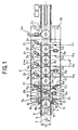
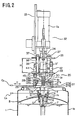
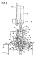
- Fig. 1 is a plan view of a first embodiment of a liquid leakage inspecting device of the present invention. Fig. 2 is an enlarged sectional view taken along the line U-U of Fig. 1. Fig. 3 is an enlarged sectional view illustrating a liquid leakage inspection performed by a leakage inspecting unit of the first embodiment. Fig. 4 is an enlarged sectional view of a conveyer of the first embodiment. Fig. 5 is an enlarged sectional view of a conveyer having a sealing stopper unit in the mouth portion of the first embodiment. Fig. 6 is an enlarged sectional view of a second embodiment of the present invention. Fig. 7 is an enlarged sectional view of a conventional beer container having a sealing stopper unit in the mouth portion. Fig. 8 is a plan view of one example of a conventional liquid leakage inspecting device. Fig. 9 is an enlarged front view of a probe and a feed unit in the leakage inspecting unit of the conventional liquid leakage inspecting device.
- Figs. 1 to 5 illustrates the first embodiment of the present invention. In these figures,
reference numeral 1 indicates a container to be transported on a production line, i.e., abarreling line 3, by aconveyer 2. Thecontainer 1 is barrel-shaped and made of an aluminum plate or steel plate. A mouth portion 1a is formed on the upper surface of thecontainer 1. Thecontainer 1 can vary in size and capacity, such as 7 litters, 10 litters, 15 litters, 20 litters, 25 litters, or 50 litters. - A sealing
stopper unit 4 which is substantially the same as the conventional sealing stopper unit is disposed in the mouth portion 1a of thecontainer 1. Aconcave portion 5 is formed on the upper portion of the sealingstopper unit 4. - The sealing
stopper unit 4 comprises abush 6, a liquid raising cylindrical member 7, agas valve 9, and asolution valve 11. Thebush 6 is disposed in the mouth portion 1a of thecontainer 1. The liquid raising cylindrical member 7 is inserted into thebush 6 by the pushing force offirst springs 8 so that oneend 7a of the liquid raising cylindrical member 7 extends deep into thecontainer 1. Agas valve 9 is disposed on the outer periphery of the upper surface of the liquid raising cylindrical member 7, and is rotatably attached to the inner surface of thebush 6. Thesolution valve 11 is disposed in the upper portion inside the liquid raising cylindrical member 7 by the pushing force of second springs 10. Thesolution valve 11 can be opened and closed. When thegas valve 9 is opened, a pressure gas G such as carbon dioxide gas or compressed air is supplied into thecontainer 1, and beer B as the content liquid is raised by the welding pressure through the liquid raising cylindrical member 7. Thesolution valve 11 then discharges the content liquid from thecontainer 1. - In Fig. 1, the
conveyer 2 for transporting thecontainer 1 is a roller conveyer or a belt conveyer as in the prior art. - However, the
conveyer 2 is provided withclamp units 12 for positioning the axis center O with respect to the center line I in the longitudinal direction of the transportation passage of theconveyer 2. Theclamp units 12 hold thecontainer 1 being transported on theconveyer 2 before thecontainer 1 reaches an inspection site K where leakage of the content liquid is detected. In the next step on theconveyer 2, a secondary water filling unit 13 is provided. The secondary water filling unit 13 stops thecontainer 1 being transported on theconveyer 2, and injects pure water w into theconcave portion 5 of the mouth portion 1a of thecontainer 1 so as to measure electric conductivity of water. - Although not shown in the figures, it is possible to employ a mouth portion washing unit which washes the mouth portion 1a of the
container 1 being transported on theconveyer 2 by supplying pure water to the mouth portion 1a, and a drying unit which removes the pure water from theconcave portion 5 of the mouth portion 1a of the container by blowing dry air into theconcave portion 5 through an air supply nozzle. - The
clamp units 12 rotatably support the base portions of a pair of holdingframes 15 havingrollers 14 at both sides of theconveyer 2 withrotational axes 16. The rods of cylinders S1 as driving power sources are connected to the holding frames 15. The holding frames 15 are provided with therollers 14. When a sensor c1 detects thecontainer 1 being transported on theconveyer 2, the cylinders S1 are actuated to rotate the holding frames 15 about therotational axes 16. The outerperipheral surface 1b of thecontainer 1 is then held by therollers 14 so that thecontainer 1 being transported on theconveyer 2 can be stopped for a leakage inspection. A sensor c2 determines, before the cylinders S1 are actuated, whether the axis center O of thecontainer 1 sandwiched by therollers 14 of theclamp units 12 is matched with the center line I. -
Stopper units 17 are disposed on both sides of theconveyer 2 and the secondary water filling unit 13 at a predetermined angle with respect to the axis center O of thecontainer 1. Thestopper units 17 are formed bycontact portions 18 at the edges of the respective rods of cylinders S2 as the driving power sources. Thecontact portions 18 can be brought into contact with the outerperipheral surface 1b of thecontainer 1. When a sensor c3 detects thecontainer 1 transported to the secondary water filling unit 13, the cylinders S2 are actuated to extend the rods, so that thecontact portions 18 are brought into contact with thecontainer 1 to stop thecontainer 1 in a predetermined position on theconveyer 2. - The
conveyer 2 of this embodiment is provided with amovable guide bar 19 which can be moved in a direction perpendicular to the transportation direction of thecontainer 1 by the driving force of the cylinder S3 in accordance with the size of thecontainer 1. Theguide bar 19 extends along theconveyer 2, and the outerperipheral surface 1b of thecontainer 1 is brought into contact with theguide bar 19. On the opposite side to theguide bar 19, a fixed guide bar 19' is disposed along theconveyer 2. - On the fixed guide bar 19' side of the
conveyer 2,stopper units 21 which stop thecontainer 1 on theconveyer 2 in accordance with its size are provided. The number of thestopper units 21 is the same as the number ofleakage inspection units 20 formed at inspection points K1, K2, K3, and K4 in the inspection site K. - The
movable guide bar 19 is disposed along one side of theconveyer 2, as shown in Figs. 1 and 4. Themovable guide bar 19 is attached to spliceplates 23 each formed at the edge of the rod of the corresponding cylinder S3 attached to a sectionally L-shapedstationary plate 22. The cylinder S3 is then actuated, and its rod is extended in accordance with the size of thecontainer 1 being transported by the cylinder S3, so that the transportation width L of theconveyer 2 can be adjusted with thecontact portions 24 of cylinders S4. Also, the axis center O' of theprobe 27 of eachleakage inspecting unit 20 is matched with the center line I of the transportation width L. - Each of the
stopper units 21 is made up of a cylinder S4 as a driving power source actuated by a sensor c4 which detects thecontainer 1 transported to the predetermined position, and acontact portion 24 which can be brought into contact with the outerperipheral surface 1b of thecontainer 1. Thecontact portion 24 is formed at the edge of the rod of the cylinder S4, which is movable toward the axis center O of thecontainer 1 by the driving force of the cylinder S4. - In the secondary water filling unit 13, the pure water w is supplied into the
concave portion 5 through a purewater supply nozzle 25 prior to the liquid leakage inspection. Theconcave portion 5 is formed in the upper portion of the sealingstopper unit 4 in the mouth portion 1a of thecontainer 1 being transported on theconveyer 2. - The
leakage inspecting units 20 are arranged in the transportation direction A of thecontainer 1, and the number of theleakage inspecting units 20 is the same as the number of the inspecting spots. In Fig. 4, the fourleakage inspecting units 20, for instance, are disposed to the four inspecting spots K1, K2, K3, and K4. Each of theleakage inspecting units 20 is detachably disposed on the upper surface of the mouth portion 1a of thecontainer 1 being transported on theconveyer 2 right under the correspondingleakage inspecting unit 20 in the inspecting site K. Here, the axis center O' of theprobe 27 corresponds to the axis center O of the mouth portion 1a of thecontainer 1, and a positioningmember 28 which can move up and down is provided so that theprobe 27 can be inserted into the mouth portion 1a. - The
positioning unit 28 is made of plastic, hard rubber, and metal. As shown in Figs. 2 and 3, thepositioning unit 28 externally has the shape of an up-side-down saucer or a bell. Thepositioning unit 28 includes an inner stand wall 28a, astep portion 28b, and aninclined guide portion 28c. The inside of thepositioning unit 28 broadens toward the bottom. The inner stand wall 28a has a larger diameter than the boundary surface T between the inner surface of the mouth portion 1a and the outer peripheral surface of thebush 6 disposed in the mouth portion 1a of thecontainer 1. Thestep portion 28b is formed on the lower surface of the inner stand wall 28a, and can be placed on the upper surface of the mouth portion 1a of thecontainer 1 in a horizontal direction Y intersecting the axis center O' of theprobe 27. Theinclined guide portion 28c matches the axis center O' of theprobe 27 with the axis center O of the container by forcibly moving thecontainer 1 in the horizontal direction Y intersecting the axis center O when theinclined guide portion 28c covers the mouth portion 1a of thecontainer 1 via thestep portion 28b. - In this embodiment, the
positioning unit 28 is incorporated into anouter casing 29 having an inclined guide portion 29a extending from theinclined guide portion 28c of thepositioning unit 28. Theouter casing 29 protects and reinforces thepositioning unit 28. Theouter casing 29 also facilitates and ensures the matching of the axis center O' of theprobe 27 with the axis center O of thecontainer 1 by making theinclined guide portion 28c long enough to keep a large contact portion for the mouth portion 1a of the container. - The
positioning unit 28 is fixed to the lower portion of anattachment plate 39 by a plurality ofattachment bolts 30. Theleading edge 27a of theprobe 27 protrudes from theattachment plate 39. - The
probe 27 has awater passing hole 27b facing awater supply unit 31 on one side of the outer peripheral surface, and anair injection hole 27c facing an air supply unit on the other side of the outer peripheral surface. Theprobe 27 is a double cylindrical electrode consisting of an outercylindrical portion 27A extending from the leading edge to the mid section, and a pillar 27B situated inside the outercylindrical portion 27A. - The outer peripheral surface of the
probe 27 is washed with the pure water w jetted from thewater supply unit 31. Furthermore, part of the pure water w is introduced forcibly into theprobe 27 through thewater passing hole 27b so as to completely wash away dust, impurities, and inspection water remaining in theprobe 27, by virtue of the surface tension during an inspection. In other words, every time theprobe 27 is inspected for liquid leakage, the inside and outside of theprobe 27 are cleaned. Thus, each inspection can be performed with high precision. - A driving
unit 32 for moving theprobe 27 up and down comprises: a cylinder S5 which serves as a driving power source attached to aframe base 33; astopper plate 35 secured by therod 34 of the cylinder S5; an attachment unit made up of a plurality ofguide bolts 36 andnuts 37; and theattachment plate 30 elastically held bysprings 38 wound around theguide bolts 36 with a distance H being kept from thestopper plate 35. When the cylinder S5 as the driving power source is actuated, therod 34 is shortened and extended to move up and down thestopper plate 35 attached to therod 34, theattachment plate 39 held and secured to the stopper plate by theguide bolts 36 and the nuts 37, and thepositioning unit 28 attached to theattachment plate 39 by theattachment bolts 30. - A sensor c5 detects the descending position of the
probe 27, and actuates the cylinder S5 to raise the rod. The descending position of the sensor c5 depends on the size of thecontainer 1 to be inspected. - A sensor c6 detects the ascending position of the
probe 27, and then actuates the cylinder S5 to lower the rod. - A
water supply nozzle 41 supplies water into theconcave portion 5 of thecontainer 1 and the inner stand wall 28a of thepositioning unit 28 disposed on the mouth portion 1a of thecontainer 1. Thewater supply nozzle 41 is included in thewater supply unit 31 for washing theprobe 27 after checking whether there is leakage of the content liquid. Thewater supply nozzle 41 is connected to awater supply pipe 42 penetrating through theattachment plate 39, and the edge of thewater supply nozzle 41 faces toward thewater passing hole 27b formed in the outer periphery of the mid section of theprobe 27. Thewater supply nozzle 41 jets the pure water w as wash water, so that the inside and outside of theprobe 27 are cleaned after each liquid leakage inspection by theprobe 27. Thus, theprobe 27 can always be prepared for the next inspection. - An
air blow nozzle 43 dries theprobe 27 washed by the water jetting from thewater supply nozzle 41 of thewater supply unit 31. Theair blow nozzle 43 is connected to anair supply pipe 44 penetrating through theattachment plate 39, and the edge of theair blow nozzle 43 faces toward theair injection hole 27c formed in the outer periphery of the mid section of theprobe 27. Every time theprobe 27 is washed by the water supplied from thewater supply nozzle 41, theair blow nozzle 43 supplies dry air or hot air to dry the inside and outside of theprobe 27. - A cylinder S6 is a rejecting cylinder for discharging the
container 1 onto areject conveyer 45 when theleakage detecting units 20 detect leakage from thecontainer 1. The rejecting cylinder S6 is disposed in a direction intersecting the transportation direction A of theconveyer 2, and is actuated when a sensor c7 detects thecontainer 1 being transported. - The first embodiment of the leakage inspecting device of the present invention has the structure as described above. The following is a description of a liquid leakage inspection method and its effects.
- First, the beer B as the content liquid is sealed into the
container 1 on the production line, or thebarreling line 3, and thecontainer 1 is then transported in an erect state on theconveyer 2. - When the censor c1 detects the
container 1 being slowly transported on theconveyer 2, the cylinders S1 as the driving power source of theclamp units 12 disposed on both sides of theconveyer 2 are actuated to extend the rod. Here, the holding frames 15 connected to the rod are rotated about therotational axes 16. Thecontainer 1 is held by therollers 14 attached to the holding frames 15 so as to avoid congestion during the transportation. - The
conveyer 2 may be stopped at the same time that theclamp units 12 hold thecontainer 1, but theconveyer 2 may also be kept in operation for higher efficiency of inspection and transportation of thecontainer 1. If a belt conveyer is used as theconveyer 2, thecontainer 1 should be transported slowly enough to restrict the friction between the bottom of thecontainer 1 and the belt conveyer, so that theclamp units 12 can match the axis center O of thecontainer 1 with the center line I of theconveyer 2. Here, the extension of the rods of the cylinders S1 are controlled based on the size of thecontainer 1, so that the axis center O of thecontainer 1 can be matched with the center line I of theconveyer 2. Also, the axis center O' of theprobe 27 of theleakage inspecting units 20 used for inspection corresponds to the center line I of theconveyer 2. - If a roller conveyer is used as the
conveyer 2, the roller around the rotational axis should rotate by virtue of the rotational force of the rotational axis. When theclamp units 2 hold thecontainer 1, the rotational axis of the roller conveyer of the above type spins without engaging the roller. In such a case, it is not necessary to stop theconveyer 2 to efficiently stop thecontainer 1 on theconveyer 2 or resume the transportation of thecontainer 1. - When the
clamp units 12 hold thecontainer 1 and the sensor c2 detects a stop of the transportation of thecontainer 1 on theconveyer 2, the cylinders S1 as the driving power sources are restarted to shorten the rods of the cylinders S1, and the holding frames 15 are rotated with therollers 14 about therotational axes 16. Thus, the holding frames 15 are opened, and thecontainer 1 is transported to the next stage by theconveyer 2. - When the sensor c3 detects the
container 1 transported to the secondary water filling unit 13 by theconveyer 2, the cylinders S2 as the driving power sources for thestopper units 17 are actuated to extend the rods, and thecontainer 1 being transported on theconveyer 2 is brought into contact with thecontact portions 18 formed at the edges of the respective rods, thereby stopping the transportation of thecontainer 1. - When the
container 1 is stopped, the purewater supply nozzle 25 supplies the pure water w into theconcave portion 5 formed in the upper portion of the sealingstopper unit 4 in the mouth portion 1a of thecontainer 1. Since the extension of the rods of the cylinders S2 is controlled so that the axis center O of thecontainer 1 corresponds to the center line I of theconveyer 2, theconcave portion 5 can be surely filled with the pure water w. - The
container 1 having the pure water w in theconcave portion 5 is then transported to emptyleakage inspecting units 20 among the fourleakage inspecting units 20 of this embodiment formed on theconveyer 2 adjacent to the secondary water filling unit 13. - When the sensor c4 detects the
container 1 transported to one of theleakage inspecting units 20 at the inspection points K1, K2, K3, and K4, the cylinder S4 of thestopper unit 21 disposed on one side of theconveyer 2 is actuated to extend its rod toward the axis center O of thecontainer 1. Here, thecontact portion 24 formed at the edge of the rod is brought into contact with one side of the outerperipheral surface 1b of thecontainer 1, and theguide bar 19 disposed on the other side of theconveyer 2 is brought into contact with the other side of the outerperipheral surface 1b of thecontainer 1. Thus, thecontact portion 24 and theguide bar 19 softly hold thecontainer 1 at one of the inspection points K1, K2, K3, and K4. - Since the
guide bar 19 is attached to thesplice plates 23 provided to the edges of the respective rods of the cylinders S3 attached to the sectionally L-shapedfixed plates 22, the cylinders S3 are actuated to extend the rods in accordance with the size of thecontainer 1, thereby adjusting the transportation width L of theconveyer 2. Also, thecontainer 1 is free of unnecessary pressure, because thecontainer 1 is stopped on theconveyer 2, with one side of the outerperipheral surface 1b being in contact with theguide bar 19, and the other side of the outerperipheral surface 1b being in contact with thecontact portion 24 on the extended rod of thestopper unit 21. Here, the outerperipheral surface 1b of thecontainer 1 can be prevented from being deformed or damaged, so that thecontainer 1 can be repeatedly used. Also, thecontainer 1 is stopped at a point where the axis center O of thecontainer 1 is matched with the center line I. Thus, the positioning and transportation of thecontainer 1 can be surely carried out. - When the sensor c4 detects the
container 1 being transported directly under one of theleakage inspecting units 20 at the inspection points K1, K2, K3, and K4, the cylinder S5 as the driving power source is actuated to extend the rod, so that theprobe 27 descends toward thecontainer 1, together with thestopper plate 35 provided to the edge of the rod, and theattachment plate 39 attached to thestopper plate 35 by theguide bolts 36. - Since the
positioning unit 28 having theinclined guide portion 28c is attached to the lower portion of theattachment plate 29 by theattachment bolts 30, theinclined guide portion 28c of thepositioning unit 28 is brought into contact with the mouth portion 1a of thecontainer 1 when the cylinder S5 is actuated to extend the rod. Accordingly, as thepositioning unit 28 is moved downward, thecontainer 1 is forcibly moved along theconveyer 2 in the horizontal direction Y. After the axis center O of thecontainer 1 is forcibly matched with the axis center O'' of thepositioning unit 28, thestep portion 28b of thepositioning unit 28 is placed on the upper surface of thecontainer 1, thereby covering the mouth portion 1a of thecontainer 1 with thepositioning unit 28. Theprobe 27 is inserted into the inner stand wall 28a formed in thepositioning unit 28, with the axis center O' of theprobe 27 being matched with the axis center O'' of thepositioning unit 28. Because of this, thecontainer 1 can be prevented from being wrongly judged to be a defective product due to the contact between the mouth portion 1a of thecontainer 1 and theprobe 27. Thus, each inspection can be performed with high precision. Also, the descending position of theprobe 27 is detected by the sensor c5 in accordance with the size of thecontainer 1. - The
positioning unit 28 is incorporated into theouter casing 29 having the inclined guide portion 29a extending from theinclined guide portion 28c, thereby making theinclined guide portions 28c and 29a as a contact portion long enough for the mouth portion 1a of thecontainer 1. Accordingly, the axis center O' of theprobe 27 can be quickly and accurately matched with the axis center O of thecontainer 1. Theouter casing 29 also protects and reinforces thepositioning unit 28. - When the sensor c5 detects the descending position, the
water supply nozzle 41 supplies pure water w into the inner stand wall 28a of thepositioning unit 28, so that the total amount of pure water w reaches the height h1 of thestep portion 28b of thepositioning unit 28 placed on the upper surface of the mouth portion 1a, as shown in Fig. 3. There is only a short distance between the secondary water filling unit 13 and theleakage inspecting unit 20 at one of the inspecting spots K1, K2, K3, and K4, and the pure water supply position corresponds to the leakage inspecting position. Thus, the pure water w can be prevented from flowing from theconcave portion 5 while thecontainer 1 is being transported on theconveyer 2. - The inner stand wall 28a formed in the
positioning unit 28 has a larger diameter than the boundary surface T between the inner surface of the mouth portion 1a of thecontainer 1 and the outer surface of thebush 6 attached to the mouth portion 1a, and is situated outside the boundary surface T. Thus, the amount of the additional pure water w supplied from thewater supply nozzle 41 corresponds to the height h1 of thepositional unit 28 placed on the mouth portion 1a. (In Fig. 3, however, since thepositioning unit 28 is incorporated into theouter casing 29, the amount of pure water w seems to correspond to the height h2 of theouter casing 29 mounted on the mouth portion 1a.) - In the above manner, the
probe 27 is inserted into the pure water w supplied into theconcave portion 5 of the mouth portion 1a of the container and the inner stand wall 28a of thepositioning unit 28 connected to theconcave portion 5, with the axis centers O and O' corresponding to each other. Even if theprobe 27 is brought into contact with the inner wall of theconcave portion 5, thecontainer 1 can be prevented form being wrongly judged to be a defective product. The electric conductivity of the inspection water (pure water w) is measured so as to judge whether the beer B as the content liquid is leaking from the mouth portion 1a of thecontainer 1. - The pure water w is supplied into the inner stand wall 28a situated outside the upper surface of the boundary surface T between the inner surface of the mouth portion 1a of the container and the outer surface of the
bush 6 attached to the mouth portion 1a. Accordingly, liquid leakage between the inner surface of the mouth portion 1a and the outer surface of thebush 6 can be detected through the inspection, as well as liquid leakage between thegas valve 9 and its valve seat in the sealingstopper unit 4, and between thesolution valve 11 and its valve seat. - After the electric conductivity of the water is measure, the cylinder S5 is actuated to shorten the
rod 34. Thestopper plate 35 mounted on therod 34 and theprobe 27 attached to theattachment plate 39 attached to thestopper plate 35 by theguide bolts 36 via the distance H then ascend to the original position. When the sensor c6 detects theprobe 27 back in its original position, thewater supply nozzle 41 of thewater supply unit 31 jets the pure water to wash theprobe 27. Here, the pure water w supplied from thewater supply nozzle 41 surely washes not only the outercylindrical portion 27A of theprobe 27, but also the inner surface of the outercylindrical portion 27A and the pillar 27B through thewater passing hole 27b formed in the outercylindrical portion 27A of theprobe 27. - The
air blow nozzle 43 of the air supply unit blows hot air or dry air to dry the washedprobe 27, thereby preparing theprobe 27 for the next liquid leakage inspection. - The cylinder S4 of the
stopper unit 21 is then actuated to shorten the rod, and the transportation passage A of theconveyer 2 is opened to transport the inspectedcontainer 1. If thecontainer 1 is judged to be a defective product, the reject cylinder S6 is actuated so that the rod is extended to discharge thedefective container 1 to thereject conveyer 45. - Fig. 6 illustrates another embodiment of the present invention.
- In the first embodiment, the
positioning unit 28 is attached to theattachment plate 39, which is moved up and down by therod 34 of the cylinder S6 of theleakage inspecting unit 20. When thecontainer 1 is inspected, thepositioning unit 28 is placed on the mouth portion 1a to supply the pure water w. - In the second embodiment, however, the
positioning unit 28 is formed separately from theattachment plate 39, to which theprobe 27 is attached. - More specifically, when the
positioning unit 28 is placed on the mouth portion 1a of thecontainer 1, a supportingunit 51 rotatable about a rotational axis 40 in the horizontal direction above theconveyer 2 moves thepositioning unit 28 in the parallel direction with the mouth portion 1a of thecontainer 1. Thepositioning unit 28 is then moved up and down, and is placed on the mouth portion 1a, so that the axis center O'' of thepositioning unit 28 corresponds to the axis center O of the mouth portion 1a of thecontainer 1. Thewater supply nozzle 41 then supplies the pure water w into thepositioning unit 28 to judge whether the content liquid is leaking. After the inspection, thepositioning unit 28 is removed from thecontainer 1. - In the above embodiments, the
probe 27 moves up and down with respect to the mouth portion 1a of thecontainer 1 being transported on theconveyer 2 by the driving force of the cylinder S5, and theprobe 27 performs a leakage inspection to judge whether the content liquid is leaking from the mouth portion 1a. However, thecontainer 1 may be moved up and down with respect to a fixedprobe 27 to perform a leakage inspection. - As described so far, in the present invention, the pure water injection position on the conveyer corresponds to the liquid leakage inspection position. In the inspection position, the pure water is injected into the concave portion formed in the mouth portion of the container and the positioning unit placed on the mouth portion, so that the pure water used in the inspection can be prevented from flowing out of the container during the transportation. The electric conductivity of the water can be measured with high accuracy, and defective products can be precisely detected. Thus, highly efficient inspection can be carried out.
- In the prior art, liquid leakage cannot be detected from the boundary surface between the inner surface of the mouth portion and the outer surface of the bush. In the present invention, however, the positioning unit having an inner stand wall having a larger diameter than the boundary surface is placed on the mouth portion of the container, thereby enabling quick and accurate leakage detection from the boundary surface.
- In the liquid leakage inspecting device of the present invention, the positioning unit is placed on the upper surface of the mouth portion of the container provided with the sealing stopper unit, and the probe is then inserted to measure the electric conductivity of the water to check for liquid leakage. The liquid leakage inspecting device of this structure is simple and does not require a large number of components. Accordingly, the production procedures can be simplified, and the production costs can be reduced.
- Also, the movable guide bar is disposed on one side of the conveyer, so that the transportation width of the conveyer can be adjusted in accordance with the size of the container. Here, the axis center of the probe of the leakage inspecting unit is substantially matched with the center line situated in the longitudinal direction of the transportation width of the conveyer. Because of this, no strong force is required for holding the container being transported on the conveyer. Thus, the container can be prevented from being deformed or damaged. Also, the axis center matching, positioning, stopping, and transporting are all readily and surely performed. Thus, the container can be repeatedly used over a long period of time.
- The inspection water for the liquid leakage inspection is supplied into the concave portion formed in the mouth portion of the container, with the water supply unit being situated exactly in the location of the concave portion. In this manner, the concave portion can be sufficiently filled with the inspection water, and the probe can be prevented from being situated outside the concave portion and from touching the inner surface of the concave portion. Thus, the liquid leakage inspection can be performed with high precision, without wrong judgements.
- The movable guide bar formed on one side of the conveyer simplifies the structure of the liquid leakage inspecting device of the present invention. Thus, the production procedures can be simplified accordingly, and the production costs can be reduced. Also, it is easy to adjust the transportation width of the conveyer in accordance with the size of the container.
- As described so far, the liquid leakage device of the present invention is provided with the water supply unit for supplying wash water into the upper position of the probe in the inspecting position, and the air supply unit for blowing dry air or hot air. Thus, the washing and drying of the probe for accurate inspection can be quickly carried out with little trouble. Also, the production procedures can be simplified, and the production and equipment costs can be reduced.
Claims (10)
- A leakage inspecting device which has a sealing stopper unit comprising: a bush attached to a mouth portion of a container containing liquid such as beer being transported on a conveyer; a liquid raising cylindrical member movably inserted into the bush in a vertical direction; a gas valve which is opened and closed, is formed on an outer periphery of an upper surface of the liquid raising cylindrical member, and is engageable with an inner surface of an upper portion of the bush; and a solution valve which raises the content liquid through the liquid raising cylindrical member by supplying pressure air into the container when the gas valve is opened, and then discharges the content liquid out of the container, and which device measures electric conductivity of water by inserting a probe after injecting pure water into a concave portion formed in an upper portion of the sealing stopper unit in the mouth portion of the container, thereby judging whether the content liquid is leaking,
which leakage inspecting device comprising: a unit which places a positioning member on the mouth portion of the container being transported on the conveyer at an inspecting spot, with an axis center of the positioning member corresponding to an axis center of the mouth portion of the container; a unit which places an inner stand wall onto an upper surface of the mouth portion and also situates the inner stand wall on an outer periphery of the mouth portion, the inner stand wall being formed inside the positioning unit and having a larger diameter than a boundary surface between the mouth portion of the container and the bush attached to the mouth portion; a unit which inject the pure water into the inner stand wall and the concave portion formed in the mouth portion connected to the inner stand wall; and a unit which measures the electric conductivity of the water by inserting the probe into the pure water injected into the inner stand wall and the concave portion of the mouth portion, thereby judging whether the content liquid is leaking from the container. - The leakage inspecting device according to claim 1, wherein: the positioning unit which is capable of covering the mouth portion of the container being transported on the conveyer is movable up and down; and an inclined guide portion which forcibly moves the container in an axis center direction thereof by touching the mouth portion is formed on an inner surface of a lower portion of the positioning unit.
- The leakage inspecting device according to claim 1 or 2, wherein the container and the probe are moved up and down relatively with each other by driving power sources, and the probe is inserted into the mouth portion of the container.
- The leakage inspecting device according to one of claims 1 to 3, wherein the positioning unit is secured below an attachment plate in such a manner that the positioning unit is placed onto the mouth portion, and the probe having a protruding edge is attached to the attachment plate.
- The leakage inspecting device according to one of claims 1 to 4, wherein the positioning unit is disposed separately from an attachment plate in such a manner that the positioning unit is placed onto the mouth portion, and the probe having a protruding edge is attached to the attachment plate.
- The leakage inspecting device according to one of claims 1 to 5, wherein: the positioning unit is externally shaped like an upside-down saucer or a bell; a step portion which is placed on an upper rim of the mouth portion of the container is formed on a lower surface of the inner stand wall, the step portion intersecting the axis center; and an inclined guide portion which broadens downward is formed under the step portion, the inclined guide portion matching axis centers with each other by forcibly moving the mouth portion of the container in a horizontal direction intersecting the axis center when the positioning unit covers the mouth portion.
- The leakage inspecting device according to claim 1 or 2, wherein a movable guide bar which adjusts a transportation width of the conveyer in accordance with the size of the container being transported is attached to one side of the conveyer, and an axis center of the probe of the leakage inspecting unit corresponds to a center line extending in a longitudinal direction of the transportation width.
- The leakage inspecting device according to claim 7, wherein: the conveyer is provided with a stopper unit comprising the guide bar movable in a direction intersecting a transportation direction of the container by a driving force of a cylinder as a driving power source on one side of the conveyer, and a rod which is movable toward the axis center of the container by a driving force of another cylinder, and is brought into contact with an outer peripheral surface of the container; and extension lengths of rods of the two cylinders are controlled in accordance with the size of the container being transported, so that the axis center of the probe is matched with the center line of the transportation width of the conveyer.
- The leakage inspecting device according to claim 1 or 2, further comprising a water supply unit which supplies wash water to the probe and an air supply unit which blows dry air or hot air to the probe, the water supply unit and the air supply unit being situated in an ascending position of the probe in an inspecting position.
- The leakage inspecting device according to claim 9, wherein the probe has a water passing hole which communicates with the water supply unit and an air injection hole which communicates with the water supply unit, the water passing hole and the air injection hole being situated on an outer periphery of the probe.
Priority Applications (1)
| Application Number | Priority Date | Filing Date | Title |
|---|---|---|---|
| DK98961540T DK0964236T3 (en) | 1997-12-25 | 1998-12-24 | Device for checking a liquid leakage container |
Applications Claiming Priority (7)
| Application Number | Priority Date | Filing Date | Title |
|---|---|---|---|
| JP35824097 | 1997-12-25 | ||
| JP35823897A JP4002945B2 (en) | 1997-12-25 | 1997-12-25 | Liquid leakage inspection method and leakage inspection apparatus |
| JP35823897 | 1997-12-25 | ||
| JP35823997 | 1997-12-25 | ||
| JP35823997A JPH11183311A (en) | 1997-12-25 | 1997-12-25 | Leakage inspecting device for content liquid |
| JP35824097A JPH11183312A (en) | 1997-12-25 | 1997-12-25 | Leakage inspecting device for content liquid |
| PCT/JP1998/005885 WO1999034188A1 (en) | 1997-12-25 | 1998-12-24 | Apparatus for inspecting container for leakage of liquid |
Publications (3)
| Publication Number | Publication Date |
|---|---|
| EP0964236A1 true EP0964236A1 (en) | 1999-12-15 |
| EP0964236A4 EP0964236A4 (en) | 2000-06-14 |
| EP0964236B1 EP0964236B1 (en) | 2005-06-15 |
Family
ID=27341574
Family Applications (1)
| Application Number | Title | Priority Date | Filing Date |
|---|---|---|---|
| EP98961540A Expired - Lifetime EP0964236B1 (en) | 1997-12-25 | 1998-12-24 | Apparatus for inspecting containers for leakage of liquid |
Country Status (4)
| Country | Link |
|---|---|
| US (1) | US6367312B1 (en) |
| EP (1) | EP0964236B1 (en) |
| DE (1) | DE69830567T2 (en) |
| WO (1) | WO1999034188A1 (en) |
Families Citing this family (4)
| Publication number | Priority date | Publication date | Assignee | Title |
|---|---|---|---|---|
| WO2002103318A1 (en) * | 2001-06-15 | 2002-12-27 | Smithkline Beecham Corporation | Apparatus and method for measuring forces imparted on valve assemblies of metered dose delivery containers during manufacture thereof |
| US20040140812A1 (en) * | 2003-01-21 | 2004-07-22 | Ademir Scallante | Arrangements containing electrical assemblies and methods of cleaning such electrical assemblies |
| IT201700097976A1 (en) * | 2017-08-31 | 2019-03-03 | Co Mac Srl | Device and method for detecting micro-leaks from drums and similar containers |
| CN115060422B (en) * | 2022-08-18 | 2022-10-28 | 山东昊特自动化仪表有限公司 | Fluid tightness testing device for valve production |
Family Cites Families (10)
| Publication number | Priority date | Publication date | Assignee | Title |
|---|---|---|---|---|
| JPS6252425A (en) * | 1985-08-30 | 1987-03-07 | ドツドウエル・エンド・コムパニ−・リミテツド | Pre-treatment method in detection of leakage of liquid |
| JPH0781926B2 (en) * | 1985-09-27 | 1995-09-06 | 株式会社吉野工業所 | Method and apparatus for inspecting air tightness of synthetic resin bottle container |
| JPS62165136A (en) * | 1986-01-17 | 1987-07-21 | Sapporo Breweries Ltd | Solution leak detector |
| US4852392A (en) * | 1988-08-12 | 1989-08-01 | Evans Robert G | High pressure drum testing apparatus and method |
| JPH03269232A (en) * | 1990-03-19 | 1991-11-29 | Nippon Sangyo Denshi Kk | Beer leakage detecting apparatus |
| AT396782B (en) * | 1991-12-23 | 1993-11-25 | Lisec Peter | DEVICE FOR PROMOTING INSULATED GLASS PANELS INCLUDING SOMETHING RIGHT |
| US5307685A (en) * | 1992-04-24 | 1994-05-03 | Bwi Kartridgpak Co. | Pressure tester and method of testing therewith |
| JP3344777B2 (en) * | 1993-07-22 | 2002-11-18 | サッポロビール株式会社 | Liquid leak inspection device |
| US5638659A (en) * | 1995-12-22 | 1997-06-17 | Riverwood International Corporation | Packaging machine |
| US5935523A (en) * | 1997-05-29 | 1999-08-10 | Medical Laboratory Automation, Inc. | Apparatus for accessing a sealed container |
-
1998
- 1998-12-24 DE DE69830567T patent/DE69830567T2/en not_active Expired - Fee Related
- 1998-12-24 EP EP98961540A patent/EP0964236B1/en not_active Expired - Lifetime
- 1998-12-24 WO PCT/JP1998/005885 patent/WO1999034188A1/en active IP Right Grant
- 1998-12-24 US US09/380,064 patent/US6367312B1/en not_active Expired - Fee Related
Non-Patent Citations (2)
| Title |
|---|
| No further relevant documents disclosed * |
| See also references of WO9934188A1 * |
Also Published As
| Publication number | Publication date |
|---|---|
| DE69830567T2 (en) | 2005-12-15 |
| EP0964236A4 (en) | 2000-06-14 |
| US6367312B1 (en) | 2002-04-09 |
| DE69830567D1 (en) | 2005-07-21 |
| EP0964236B1 (en) | 2005-06-15 |
| WO1999034188A1 (en) | 1999-07-08 |
Similar Documents
| Publication | Publication Date | Title |
|---|---|---|
| JPH07500289A (en) | Continuous work inspection machine for containers | |
| US6367312B1 (en) | Apparatus for inspecting container for leakage of liquid | |
| US4852392A (en) | High pressure drum testing apparatus and method | |
| US11543323B2 (en) | Leak tester | |
| JP3383517B2 (en) | Automatic quality inspection system for beverage cans | |
| JP3703614B2 (en) | Liquid leakage inspection device | |
| JPH11183310A (en) | Leakage inspecting method and leakage inspecting device for content liquid | |
| JP2004205453A (en) | Leak inspection device for pet bottle | |
| JP2559967B2 (en) | Leak inspection device for Otaru | |
| JPH09166293A (en) | Gas charger | |
| JPH11183312A (en) | Leakage inspecting device for content liquid | |
| JPH11183311A (en) | Leakage inspecting device for content liquid | |
| KR102016582B1 (en) | Pinhole inspection device for container for the prevention of the remaining contents | |
| JP4248966B2 (en) | Cup leak inspection device | |
| JPH0791598A (en) | Gas filling device | |
| JPH0961281A (en) | Leak tester for drum | |
| CN112798246B (en) | Spraying state detection device of perfume shower nozzle | |
| JP4258928B2 (en) | Filling weight inspection device for filling machine | |
| JP2004361207A (en) | Method and device for inspecting leak of sealed packaging container | |
| GB2164029A (en) | Automatic fining and top-up machine | |
| KR0171668B1 (en) | Test device of semiconductor package | |
| KR20040012065A (en) | Transfer apparatus of nuclear fuel rod for eddy current testing | |
| CN220062888U (en) | Detection device for surface smoothness of wafer chuck | |
| CN106430046A (en) | High-precision automatic covering machine | |
| KR100228580B1 (en) | Inferior battery ejecting apparatus |
Legal Events
| Date | Code | Title | Description |
|---|---|---|---|
| PUAI | Public reference made under article 153(3) epc to a published international application that has entered the european phase |
Free format text: ORIGINAL CODE: 0009012 |
|
| 17P | Request for examination filed |
Effective date: 19990924 |
|
| AK | Designated contracting states |
Kind code of ref document: A1 Designated state(s): BE DE DK FR GB NL |
|
| A4 | Supplementary search report drawn up and despatched |
Effective date: 20000502 |
|
| AK | Designated contracting states |
Kind code of ref document: A4 Designated state(s): BE DE DK FR GB NL |
|
| 17Q | First examination report despatched |
Effective date: 20040405 |
|
| GRAP | Despatch of communication of intention to grant a patent |
Free format text: ORIGINAL CODE: EPIDOSNIGR1 |
|
| RTI1 | Title (correction) |
Free format text: APPARATUS FOR INSPECTING CONTAINERS FOR LEAKAGE OF LIQUID |
|
| RAP1 | Party data changed (applicant data changed or rights of an application transferred) |
Owner name: TOA MANUFACTURING COMPANY Owner name: SUNTORY LIMITED Owner name: SAPPORO BREWERIES LTD. |
|
| GRAS | Grant fee paid |
Free format text: ORIGINAL CODE: EPIDOSNIGR3 |
|
| GRAA | (expected) grant |
Free format text: ORIGINAL CODE: 0009210 |
|
| AK | Designated contracting states |
Kind code of ref document: B1 Designated state(s): BE DE DK FR GB NL |
|
| DAX | Request for extension of the european patent (deleted) | ||
| REG | Reference to a national code |
Ref country code: GB Ref legal event code: FG4D |
|
| REG | Reference to a national code |
Ref country code: DK Ref legal event code: T3 |
|
| REF | Corresponds to: |
Ref document number: 69830567 Country of ref document: DE Date of ref document: 20050721 Kind code of ref document: P |
|
| RAP2 | Party data changed (patent owner data changed or rights of a patent transferred) |
Owner name: TOA MANUFACTURING COMPANY Owner name: SUNTORY LIMITED Owner name: SAPPORO BREWERIES LTD. |
|
| RAP2 | Party data changed (patent owner data changed or rights of a patent transferred) |
Owner name: TOA MANUFACTURING COMPANY Owner name: SUNTORY LIMITED Owner name: SAPPORO BREWERIES LIMITED |
|
| NLT2 | Nl: modifications (of names), taken from the european patent patent bulletin |
Owner name: SAPPORO BREWERIES LTD. EN SUNTORY LIMITED EN TOA M Effective date: 20050817 |
|
| NLT2 | Nl: modifications (of names), taken from the european patent patent bulletin |
Owner name: SAPPORO BREWERIES LIMITED EN SUNTORY LIMITED EN TO Effective date: 20050928 |
|
| ET | Fr: translation filed | ||
| PLBE | No opposition filed within time limit |
Free format text: ORIGINAL CODE: 0009261 |
|
| STAA | Information on the status of an ep patent application or granted ep patent |
Free format text: STATUS: NO OPPOSITION FILED WITHIN TIME LIMIT |
|
| 26N | No opposition filed |
Effective date: 20060316 |
|
| PGFP | Annual fee paid to national office [announced via postgrant information from national office to epo] |
Ref country code: NL Payment date: 20081215 Year of fee payment: 11 Ref country code: DK Payment date: 20081212 Year of fee payment: 11 |
|
| PGFP | Annual fee paid to national office [announced via postgrant information from national office to epo] |
Ref country code: BE Payment date: 20081017 Year of fee payment: 11 |
|
| PGFP | Annual fee paid to national office [announced via postgrant information from national office to epo] |
Ref country code: FR Payment date: 20081212 Year of fee payment: 11 |
|
| PGFP | Annual fee paid to national office [announced via postgrant information from national office to epo] |
Ref country code: DE Payment date: 20081219 Year of fee payment: 11 |
|
| PGFP | Annual fee paid to national office [announced via postgrant information from national office to epo] |
Ref country code: GB Payment date: 20081224 Year of fee payment: 11 |
|
| NLS | Nl: assignments of ep-patents |
Owner name: TOA MANUFACTURING COMPANY Effective date: 20090504 Owner name: SUNTORY HOLDINGS LIMITED Effective date: 20090504 Owner name: SAPPORO BREWERIES LTD. Effective date: 20090504 |
|
| REG | Reference to a national code |
Ref country code: FR Ref legal event code: TQ |
|
| BERE | Be: lapsed |
Owner name: TOA MFG CY Effective date: 20091231 Owner name: SUNTORY HOLDINGS LTD Effective date: 20091231 Owner name: SAPPORO BREWERIES LTD Effective date: 20091231 |
|
| REG | Reference to a national code |
Ref country code: NL Ref legal event code: V1 Effective date: 20100701 |
|
| REG | Reference to a national code |
Ref country code: DK Ref legal event code: EBP |
|
| GBPC | Gb: european patent ceased through non-payment of renewal fee |
Effective date: 20091224 |
|
| REG | Reference to a national code |
Ref country code: FR Ref legal event code: ST Effective date: 20100831 |
|
| PG25 | Lapsed in a contracting state [announced via postgrant information from national office to epo] |
Ref country code: NL Free format text: LAPSE BECAUSE OF NON-PAYMENT OF DUE FEES Effective date: 20100701 Ref country code: FR Free format text: LAPSE BECAUSE OF NON-PAYMENT OF DUE FEES Effective date: 20091231 Ref country code: BE Free format text: LAPSE BECAUSE OF NON-PAYMENT OF DUE FEES Effective date: 20091231 |
|
| PG25 | Lapsed in a contracting state [announced via postgrant information from national office to epo] |
Ref country code: DE Free format text: LAPSE BECAUSE OF NON-PAYMENT OF DUE FEES Effective date: 20100701 |
|
| PG25 | Lapsed in a contracting state [announced via postgrant information from national office to epo] |
Ref country code: GB Free format text: LAPSE BECAUSE OF NON-PAYMENT OF DUE FEES Effective date: 20091224 |
|
| PG25 | Lapsed in a contracting state [announced via postgrant information from national office to epo] |
Ref country code: DK Free format text: LAPSE BECAUSE OF NON-PAYMENT OF DUE FEES Effective date: 20100104 |