EP0964166A2 - Hydraulische Regelung - Google Patents
Hydraulische Regelung Download PDFInfo
- Publication number
- EP0964166A2 EP0964166A2 EP19990304226 EP99304226A EP0964166A2 EP 0964166 A2 EP0964166 A2 EP 0964166A2 EP 19990304226 EP19990304226 EP 19990304226 EP 99304226 A EP99304226 A EP 99304226A EP 0964166 A2 EP0964166 A2 EP 0964166A2
- Authority
- EP
- European Patent Office
- Prior art keywords
- pressure
- temperature
- valve
- control
- current
- Prior art date
- Legal status (The legal status is an assumption and is not a legal conclusion. Google has not performed a legal analysis and makes no representation as to the accuracy of the status listed.)
- Granted
Links
- 239000012530 fluid Substances 0.000 claims abstract description 11
- 230000001419 dependent effect Effects 0.000 claims abstract description 9
- 238000012544 monitoring process Methods 0.000 claims abstract description 3
- 230000000694 effects Effects 0.000 claims description 2
- 239000000725 suspension Substances 0.000 description 2
- 239000002470 thermal conductor Substances 0.000 description 1
Images

Classifications
-
- F—MECHANICAL ENGINEERING; LIGHTING; HEATING; WEAPONS; BLASTING
- F15—FLUID-PRESSURE ACTUATORS; HYDRAULICS OR PNEUMATICS IN GENERAL
- F15B—SYSTEMS ACTING BY MEANS OF FLUIDS IN GENERAL; FLUID-PRESSURE ACTUATORS, e.g. SERVOMOTORS; DETAILS OF FLUID-PRESSURE SYSTEMS, NOT OTHERWISE PROVIDED FOR
- F15B11/00—Servomotor systems without provision for follow-up action; Circuits therefor
- F15B11/02—Systems essentially incorporating special features for controlling the speed or actuating force of an output member
- F15B11/028—Systems essentially incorporating special features for controlling the speed or actuating force of an output member for controlling the actuating force
-
- F—MECHANICAL ENGINEERING; LIGHTING; HEATING; WEAPONS; BLASTING
- F15—FLUID-PRESSURE ACTUATORS; HYDRAULICS OR PNEUMATICS IN GENERAL
- F15B—SYSTEMS ACTING BY MEANS OF FLUIDS IN GENERAL; FLUID-PRESSURE ACTUATORS, e.g. SERVOMOTORS; DETAILS OF FLUID-PRESSURE SYSTEMS, NOT OTHERWISE PROVIDED FOR
- F15B21/00—Common features of fluid actuator systems; Fluid-pressure actuator systems or details thereof, not covered by any other group of this subclass
- F15B21/04—Special measures taken in connection with the properties of the fluid
- F15B21/045—Compensating for variations in viscosity or temperature
-
- F—MECHANICAL ENGINEERING; LIGHTING; HEATING; WEAPONS; BLASTING
- F15—FLUID-PRESSURE ACTUATORS; HYDRAULICS OR PNEUMATICS IN GENERAL
- F15B—SYSTEMS ACTING BY MEANS OF FLUIDS IN GENERAL; FLUID-PRESSURE ACTUATORS, e.g. SERVOMOTORS; DETAILS OF FLUID-PRESSURE SYSTEMS, NOT OTHERWISE PROVIDED FOR
- F15B2211/00—Circuits for servomotor systems
- F15B2211/20—Fluid pressure source, e.g. accumulator or variable axial piston pump
- F15B2211/205—Systems with pumps
- F15B2211/2053—Type of pump
- F15B2211/20538—Type of pump constant capacity
-
- F—MECHANICAL ENGINEERING; LIGHTING; HEATING; WEAPONS; BLASTING
- F15—FLUID-PRESSURE ACTUATORS; HYDRAULICS OR PNEUMATICS IN GENERAL
- F15B—SYSTEMS ACTING BY MEANS OF FLUIDS IN GENERAL; FLUID-PRESSURE ACTUATORS, e.g. SERVOMOTORS; DETAILS OF FLUID-PRESSURE SYSTEMS, NOT OTHERWISE PROVIDED FOR
- F15B2211/00—Circuits for servomotor systems
- F15B2211/20—Fluid pressure source, e.g. accumulator or variable axial piston pump
- F15B2211/25—Pressure control functions
-
- F—MECHANICAL ENGINEERING; LIGHTING; HEATING; WEAPONS; BLASTING
- F15—FLUID-PRESSURE ACTUATORS; HYDRAULICS OR PNEUMATICS IN GENERAL
- F15B—SYSTEMS ACTING BY MEANS OF FLUIDS IN GENERAL; FLUID-PRESSURE ACTUATORS, e.g. SERVOMOTORS; DETAILS OF FLUID-PRESSURE SYSTEMS, NOT OTHERWISE PROVIDED FOR
- F15B2211/00—Circuits for servomotor systems
- F15B2211/30—Directional control
- F15B2211/305—Directional control characterised by the type of valves
- F15B2211/3056—Assemblies of multiple valves
- F15B2211/3059—Assemblies of multiple valves having multiple valves for multiple output members
-
- F—MECHANICAL ENGINEERING; LIGHTING; HEATING; WEAPONS; BLASTING
- F15—FLUID-PRESSURE ACTUATORS; HYDRAULICS OR PNEUMATICS IN GENERAL
- F15B—SYSTEMS ACTING BY MEANS OF FLUIDS IN GENERAL; FLUID-PRESSURE ACTUATORS, e.g. SERVOMOTORS; DETAILS OF FLUID-PRESSURE SYSTEMS, NOT OTHERWISE PROVIDED FOR
- F15B2211/00—Circuits for servomotor systems
- F15B2211/30—Directional control
- F15B2211/32—Directional control characterised by the type of actuation
- F15B2211/327—Directional control characterised by the type of actuation electrically or electronically
-
- F—MECHANICAL ENGINEERING; LIGHTING; HEATING; WEAPONS; BLASTING
- F15—FLUID-PRESSURE ACTUATORS; HYDRAULICS OR PNEUMATICS IN GENERAL
- F15B—SYSTEMS ACTING BY MEANS OF FLUIDS IN GENERAL; FLUID-PRESSURE ACTUATORS, e.g. SERVOMOTORS; DETAILS OF FLUID-PRESSURE SYSTEMS, NOT OTHERWISE PROVIDED FOR
- F15B2211/00—Circuits for servomotor systems
- F15B2211/50—Pressure control
- F15B2211/52—Pressure control characterised by the type of actuation
- F15B2211/526—Pressure control characterised by the type of actuation electrically or electronically
- F15B2211/527—Pressure control characterised by the type of actuation electrically or electronically with signal modulation, e.g. pulse width modulation [PWM]
-
- F—MECHANICAL ENGINEERING; LIGHTING; HEATING; WEAPONS; BLASTING
- F15—FLUID-PRESSURE ACTUATORS; HYDRAULICS OR PNEUMATICS IN GENERAL
- F15B—SYSTEMS ACTING BY MEANS OF FLUIDS IN GENERAL; FLUID-PRESSURE ACTUATORS, e.g. SERVOMOTORS; DETAILS OF FLUID-PRESSURE SYSTEMS, NOT OTHERWISE PROVIDED FOR
- F15B2211/00—Circuits for servomotor systems
- F15B2211/50—Pressure control
- F15B2211/55—Pressure control for limiting a pressure up to a maximum pressure, e.g. by using a pressure relief valve
-
- F—MECHANICAL ENGINEERING; LIGHTING; HEATING; WEAPONS; BLASTING
- F15—FLUID-PRESSURE ACTUATORS; HYDRAULICS OR PNEUMATICS IN GENERAL
- F15B—SYSTEMS ACTING BY MEANS OF FLUIDS IN GENERAL; FLUID-PRESSURE ACTUATORS, e.g. SERVOMOTORS; DETAILS OF FLUID-PRESSURE SYSTEMS, NOT OTHERWISE PROVIDED FOR
- F15B2211/00—Circuits for servomotor systems
- F15B2211/60—Circuit components or control therefor
- F15B2211/63—Electronic controllers
- F15B2211/6303—Electronic controllers using input signals
- F15B2211/6306—Electronic controllers using input signals representing a pressure
- F15B2211/6309—Electronic controllers using input signals representing a pressure the pressure being a pressure source supply pressure
-
- F—MECHANICAL ENGINEERING; LIGHTING; HEATING; WEAPONS; BLASTING
- F15—FLUID-PRESSURE ACTUATORS; HYDRAULICS OR PNEUMATICS IN GENERAL
- F15B—SYSTEMS ACTING BY MEANS OF FLUIDS IN GENERAL; FLUID-PRESSURE ACTUATORS, e.g. SERVOMOTORS; DETAILS OF FLUID-PRESSURE SYSTEMS, NOT OTHERWISE PROVIDED FOR
- F15B2211/00—Circuits for servomotor systems
- F15B2211/60—Circuit components or control therefor
- F15B2211/63—Electronic controllers
- F15B2211/6303—Electronic controllers using input signals
- F15B2211/6343—Electronic controllers using input signals representing a temperature
-
- F—MECHANICAL ENGINEERING; LIGHTING; HEATING; WEAPONS; BLASTING
- F15—FLUID-PRESSURE ACTUATORS; HYDRAULICS OR PNEUMATICS IN GENERAL
- F15B—SYSTEMS ACTING BY MEANS OF FLUIDS IN GENERAL; FLUID-PRESSURE ACTUATORS, e.g. SERVOMOTORS; DETAILS OF FLUID-PRESSURE SYSTEMS, NOT OTHERWISE PROVIDED FOR
- F15B2211/00—Circuits for servomotor systems
- F15B2211/60—Circuit components or control therefor
- F15B2211/665—Methods of control using electronic components
- F15B2211/6653—Pressure control
-
- F—MECHANICAL ENGINEERING; LIGHTING; HEATING; WEAPONS; BLASTING
- F15—FLUID-PRESSURE ACTUATORS; HYDRAULICS OR PNEUMATICS IN GENERAL
- F15B—SYSTEMS ACTING BY MEANS OF FLUIDS IN GENERAL; FLUID-PRESSURE ACTUATORS, e.g. SERVOMOTORS; DETAILS OF FLUID-PRESSURE SYSTEMS, NOT OTHERWISE PROVIDED FOR
- F15B2211/00—Circuits for servomotor systems
- F15B2211/70—Output members, e.g. hydraulic motors or cylinders or control therefor
- F15B2211/71—Multiple output members, e.g. multiple hydraulic motors or cylinders
-
- F—MECHANICAL ENGINEERING; LIGHTING; HEATING; WEAPONS; BLASTING
- F15—FLUID-PRESSURE ACTUATORS; HYDRAULICS OR PNEUMATICS IN GENERAL
- F15B—SYSTEMS ACTING BY MEANS OF FLUIDS IN GENERAL; FLUID-PRESSURE ACTUATORS, e.g. SERVOMOTORS; DETAILS OF FLUID-PRESSURE SYSTEMS, NOT OTHERWISE PROVIDED FOR
- F15B2211/00—Circuits for servomotor systems
- F15B2211/70—Output members, e.g. hydraulic motors or cylinders or control therefor
- F15B2211/76—Control of force or torque of the output member
-
- Y—GENERAL TAGGING OF NEW TECHNOLOGICAL DEVELOPMENTS; GENERAL TAGGING OF CROSS-SECTIONAL TECHNOLOGIES SPANNING OVER SEVERAL SECTIONS OF THE IPC; TECHNICAL SUBJECTS COVERED BY FORMER USPC CROSS-REFERENCE ART COLLECTIONS [XRACs] AND DIGESTS
- Y10—TECHNICAL SUBJECTS COVERED BY FORMER USPC
- Y10T—TECHNICAL SUBJECTS COVERED BY FORMER US CLASSIFICATION
- Y10T137/00—Fluid handling
- Y10T137/2496—Self-proportioning or correlating systems
- Y10T137/2559—Self-controlled branched flow systems
- Y10T137/2574—Bypass or relief controlled by main line fluid condition
- Y10T137/2605—Pressure responsive
- Y10T137/264—Electrical control
Definitions
- the present invention relates to hydraulic control systems such as those used in the control of vehicle active suspension systems.
- an electrically operated valve such as a solenoid valve
- the present invention therefore provides a control system for a hydraulic valve block including an electrically operated valve, the system including control means arranged to supply an electric control current to the valve. and to monitor a temperature dependent parameter of the control current thereby to measure the temperature of the valve.
- the present invention further provides a hydraulic control system comprising a hydraulic circuit including a source of fluid pressure, an electrically operated valve for controlling the pressure in a part of the hydraulic circuit, a pressure transducer for producing a pressure signal indicative of the pressure in said part of the hydraulic circuit, and control means arranged to supply an electric control current to the valve to control the valve in response to signals from the pressure transducer, to monitor a temperature dependent parameter of the control current thereby to monitor the temperature of the valve, and to compensate accordingly for the effect of temperature changes on the pressure signal.
- a hydraulic control system comprising a hydraulic circuit including a source of fluid pressure, an electrically operated valve for controlling the pressure in a part of the hydraulic circuit, a pressure transducer for producing a pressure signal indicative of the pressure in said part of the hydraulic circuit, and control means arranged to supply an electric control current to the valve to control the valve in response to signals from the pressure transducer, to monitor a temperature dependent parameter of the control current thereby to monitor the temperature of the valve, and to compensate accordingly for the effect of temperature changes
- a hydraulic circuit 10 for an active vehicle suspension system comprises a pump 12 for supplying hydraulic fluid under pressure from a reservoir 14, and a valve block 16 for controlling the distribution of hydraulic fluid to various actuators (not shown) and the return of fluid to the reservoir 14.
- the valve block has a first port 18 for receiving fluid from the pump 12 and a second port 20 for the return of fluid to the reservoir 14.
- the first and second ports 18, 20 are interconnected by a diverter valve 22 which can allow fluid to flow from the first port 18 to the second port 20 to control the pressure at the first port as will be described in more detail below.
- Two further solenoid valves 24, 26 control the flow of fluid from the pump 12 to the actuators and from the actuators to the reservoir. These two valves basically connect and disconnect the actuators in the desired combination.
- a pressure transducer 28 produces a pressure signal indicative of the hydraulic pressure at the first port 18, and a control unit 30 controls the valves 22, 26, 26 in response to the pressure signal so as to regulate the pressure at the first port 18 to a desired level, and to connect the actuators to the first and second ports 18 20 in the desired combination.
- the choice of pressure produced by the diverter valve 22 is based on other inputs to the control unit 30 which are not relevant to this invention.
- the output characteristic of the pressure transducer 28 is dependent on its temperature. At a given temperature. the voltage output by the transducer is directly related to the pressure being measured. As the temperature changes, the gradient of the characteristic. i.e. the change in output voltage for a given change of pressure is the same, but the absolute value of the output voltage is altered. Thus for a first low temperature T1, the characteristic is illustrated by the line V(P) T1 , and for a second, higher temperature T2 the characteristic is illustrated by the line V(P) T2
- the output voltage for zero pressure is referred to as the offset voltage, and the change in offset voltage with temperature is the same as the change in output voltage with temperature for any given pressure.
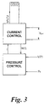
- control unit can be considered as a number of functional blocks.
- a pressure control block 32 receives a signal P d indicative of the desired pressure at the first port 18 and another signal V(P) which is the output signal from the pressure transducer. From the difference between the measured pressure and the desired pressure it produces a signal I which indicates the current which needs to be supplied to the solenoid 22a of the diverter valve 22 to produce the desired pressure at the first port 18.
- a current control block 34 receives the signal I and also has inputs connected to a battery voltage V bat . It applies the battery voltage across the solenoid 22a as a pulsed signal. monitors the driving current flowing through the solenoid as a result, and modulates the pulse width so as to produce the total current corresponding to the signal I from the pressure control block.
- the current control block sends a signal M/S back to the pressure control block indicative of the mark to space (or duty) ratio of the driving current.
- the pressure control block can determine the temperature of the pressure transducer from the relationship between the signal I and the signal M/S.
- the control unit in order to determine the pressure P corresponding to a transducer output voltage V, the control unit needs to know the gradient of the voltage / pressure characteristic, which is constant and can be stored in memory, and the offset voltage which is the output voltage at zero pressure. It is assumed that the offset voltage varies linearly with temperature, and the control unit is therefore arranged to record the output voltage V at a time when the vehicle temperature is low, e.g. when it is started up, and at another time when the vehicle temperature is high, e.g. when the engine is turned off. From estimates of the temperatures at these times the relationship between offset voltage and temperature can be estimated.
Landscapes
- Engineering & Computer Science (AREA)
- Physics & Mathematics (AREA)
- Fluid Mechanics (AREA)
- Mechanical Engineering (AREA)
- General Engineering & Computer Science (AREA)
- Chemical & Material Sciences (AREA)
- Analytical Chemistry (AREA)
- Vehicle Body Suspensions (AREA)
- Fluid-Pressure Circuits (AREA)
Applications Claiming Priority (2)
| Application Number | Priority Date | Filing Date | Title |
|---|---|---|---|
| GB9812305A GB9812305D0 (en) | 1998-06-09 | 1998-06-09 | Hydraulic control systems |
| GB9812305 | 1998-06-09 |
Publications (3)
| Publication Number | Publication Date |
|---|---|
| EP0964166A2 true EP0964166A2 (de) | 1999-12-15 |
| EP0964166A3 EP0964166A3 (de) | 2001-06-27 |
| EP0964166B1 EP0964166B1 (de) | 2005-01-05 |
Family
ID=10833392
Family Applications (1)
| Application Number | Title | Priority Date | Filing Date |
|---|---|---|---|
| EP19990304226 Expired - Lifetime EP0964166B1 (de) | 1998-06-09 | 1999-05-28 | Hydraulische Regelung |
Country Status (4)
| Country | Link |
|---|---|
| US (1) | US6209566B1 (de) |
| EP (1) | EP0964166B1 (de) |
| DE (1) | DE69923035T8 (de) |
| GB (1) | GB9812305D0 (de) |
Cited By (1)
| Publication number | Priority date | Publication date | Assignee | Title |
|---|---|---|---|---|
| NL2017106A (en) * | 2016-07-05 | 2016-10-13 | Fugro N V | Unmanned underwater vehicle and method for controlling hydraulic system |
Families Citing this family (3)
| Publication number | Priority date | Publication date | Assignee | Title |
|---|---|---|---|---|
| US7562392B1 (en) * | 1999-05-19 | 2009-07-14 | Digimarc Corporation | Methods of interacting with audio and ambient music |
| US6629411B2 (en) * | 2001-05-09 | 2003-10-07 | Valeo Electrical Systems, Inc. | Dual displacement motor control |
| US11609586B2 (en) * | 2019-10-13 | 2023-03-21 | Aaron Dwayne Lawson | Apparatuses for facilitating relieving pressure in a fluid transportation system |
Family Cites Families (5)
| Publication number | Priority date | Publication date | Assignee | Title |
|---|---|---|---|---|
| US4083001A (en) | 1976-12-29 | 1978-04-04 | Westinghouse Electric Corporation | Measurement of motor winding temperature |
| DE3437304A1 (de) | 1984-10-11 | 1986-04-17 | Licentia Patent-Verwaltungs-Gmbh, 6000 Frankfurt | Verfahren zur bestimmung der temperatur, vorzugsweise der eisgrenzschichttemperatur, eines elektrischen widerstandsheizelementes einer enteisungsanlage fuer flugzeuge, hubschrauber oder dergleichen |
| GB2277170A (en) * | 1993-04-13 | 1994-10-19 | Ford New Holland Ltd | Solenoid operated hydraulic valve |
| EP0636869B1 (de) | 1993-07-27 | 1999-01-13 | Siemens Aktiengesellschaft | Schaltungsanordnung zum Ermitteln der Temperatur einer stromgeregelten elektrischen Spule |
| JPH10119529A (ja) * | 1996-10-18 | 1998-05-12 | Tokico Ltd | サスペンション制御装置 |
-
1998
- 1998-06-09 GB GB9812305A patent/GB9812305D0/en not_active Ceased
-
1999
- 1999-05-26 US US09/320,068 patent/US6209566B1/en not_active Expired - Lifetime
- 1999-05-28 EP EP19990304226 patent/EP0964166B1/de not_active Expired - Lifetime
- 1999-05-28 DE DE1999623035 patent/DE69923035T8/de active Active
Non-Patent Citations (1)
| Title |
|---|
| None |
Cited By (4)
| Publication number | Priority date | Publication date | Assignee | Title |
|---|---|---|---|---|
| NL2017106A (en) * | 2016-07-05 | 2016-10-13 | Fugro N V | Unmanned underwater vehicle and method for controlling hydraulic system |
| WO2018009057A1 (en) * | 2016-07-05 | 2018-01-11 | Fugro N.V. | Unmanned underwater vehicle and method for controlling hydraulic system |
| US10759509B2 (en) | 2016-07-05 | 2020-09-01 | Fugro N.V. | Unmanned underwater vehicle and method for controlling hydraulic system |
| AU2017293294B2 (en) * | 2016-07-05 | 2023-07-13 | Fugro N.V. | Unmanned underwater vehicle and method for controlling hydraulic system |
Also Published As
| Publication number | Publication date |
|---|---|
| DE69923035T2 (de) | 2005-12-22 |
| EP0964166B1 (de) | 2005-01-05 |
| DE69923035D1 (de) | 2005-02-10 |
| US6209566B1 (en) | 2001-04-03 |
| DE69923035T8 (de) | 2007-05-16 |
| GB9812305D0 (en) | 1998-08-05 |
| EP0964166A3 (de) | 2001-06-27 |
Similar Documents
| Publication | Publication Date | Title |
|---|---|---|
| US7950378B2 (en) | Glow plug control unit and method for controlling the temperature in a glow plug | |
| US7997117B2 (en) | Electrically controlled hydraulic valve calibration method and system | |
| US10381913B2 (en) | Power supply control device and control characteristic correction data generation method for power supply control device | |
| US8918257B2 (en) | Transmission control apparatus and adjustment method for output characteristic thereof | |
| US7377480B2 (en) | Electrohydraulic valve servomechanism with adaptive resistance estimator | |
| JP2002021806A (ja) | 油圧作動装置の自動較正システム及び自動較正方法 | |
| JP2000056836A (ja) | 変圧式のハイドロリック系 | |
| KR101864911B1 (ko) | 연료의 온도를 결정하는 방법 | |
| KR101422285B1 (ko) | 전류 피드백의 자체보정을 위한 장치 및 방법 | |
| US20030121409A1 (en) | System and method for controlling hydraulic flow | |
| HUT55686A (en) | Electronic brake system | |
| US6209566B1 (en) | Hydraulic control systems | |
| US20030179534A1 (en) | Method and a device for operating an electro-magnet on an intrinsically safe direct current circuit | |
| US5454291A (en) | Electrohydraulic regulating device having pulse width modulating valves with an adjusting signal | |
| JPH0792033A (ja) | 電流制御式電気コイルの温度を検出するための回路装置 | |
| JP4928032B2 (ja) | 電気的負荷を制御するための方法および装置 | |
| JP4443280B2 (ja) | ソレノイドのプランジャ位置検出装置および電磁弁および方向切換弁 | |
| GB2338305A (en) | Monitoring valve temperature in a hydraulic control system | |
| US6679800B1 (en) | Hydraulic pressure control method and apparatus of an automatic transmission for a vehicle | |
| CN1333233C (zh) | 用于远程装置的双线输出/供电机构及其方法 | |
| US5699824A (en) | Electrical-pneumatic system | |
| CN101644259B (zh) | 用于调节旋转泵的输送容积的调节阀 | |
| US12188576B2 (en) | Method and apparatus for diagnosing abnormal state of valve | |
| KR100721382B1 (ko) | 솔레노이드 코일의 온도 측정 장치 | |
| KR100721370B1 (ko) | 솔레노이드 밸브의 제어방법 |
Legal Events
| Date | Code | Title | Description |
|---|---|---|---|
| PUAI | Public reference made under article 153(3) epc to a published international application that has entered the european phase |
Free format text: ORIGINAL CODE: 0009012 |
|
| AK | Designated contracting states |
Kind code of ref document: A2 Designated state(s): DE ES FR IT SE |
|
| AX | Request for extension of the european patent |
Free format text: AL;LT;LV;MK;RO;SI |
|
| PUAL | Search report despatched |
Free format text: ORIGINAL CODE: 0009013 |
|
| RAP1 | Party data changed (applicant data changed or rights of an application transferred) |
Owner name: LAND ROVER GROUP LIMITED |
|
| AK | Designated contracting states |
Kind code of ref document: A3 Designated state(s): AT BE CH CY DE DK ES FI FR GB GR IE IT LI LU MC NL PT SE |
|
| AX | Request for extension of the european patent |
Free format text: AL;LT;LV;MK;RO;SI |
|
| 17P | Request for examination filed |
Effective date: 20011112 |
|
| AKX | Designation fees paid |
Free format text: DE ES FR IT SE |
|
| 17Q | First examination report despatched |
Effective date: 20021203 |
|
| GRAP | Despatch of communication of intention to grant a patent |
Free format text: ORIGINAL CODE: EPIDOSNIGR1 |
|
| GRAS | Grant fee paid |
Free format text: ORIGINAL CODE: EPIDOSNIGR3 |
|
| GRAA | (expected) grant |
Free format text: ORIGINAL CODE: 0009210 |
|
| RBV | Designated contracting states (corrected) |
Designated state(s): DE ES FR IT SE |
|
| AK | Designated contracting states |
Kind code of ref document: B1 Designated state(s): DE FR |
|
| RBV | Designated contracting states (corrected) |
Designated state(s): DE FR |
|
| REF | Corresponds to: |
Ref document number: 69923035 Country of ref document: DE Date of ref document: 20050210 Kind code of ref document: P |
|
| PLBE | No opposition filed within time limit |
Free format text: ORIGINAL CODE: 0009261 |
|
| STAA | Information on the status of an ep patent application or granted ep patent |
Free format text: STATUS: NO OPPOSITION FILED WITHIN TIME LIMIT |
|
| 26N | No opposition filed |
Effective date: 20051006 |
|
| ET | Fr: translation filed | ||
| REG | Reference to a national code |
Ref country code: FR Ref legal event code: TP |
|
| REG | Reference to a national code |
Ref country code: DE Ref legal event code: R082 Ref document number: 69923035 Country of ref document: DE Representative=s name: ANDRAE WESTENDORP PATENTANWAELTE PARTNERSCHAFT, DE |
|
| REG | Reference to a national code |
Ref country code: FR Ref legal event code: PLFP Year of fee payment: 18 |
|
| REG | Reference to a national code |
Ref country code: FR Ref legal event code: PLFP Year of fee payment: 19 |
|
| REG | Reference to a national code |
Ref country code: FR Ref legal event code: PLFP Year of fee payment: 20 |
|
| PGFP | Annual fee paid to national office [announced via postgrant information from national office to epo] |
Ref country code: DE Payment date: 20180419 Year of fee payment: 20 |
|
| PGFP | Annual fee paid to national office [announced via postgrant information from national office to epo] |
Ref country code: FR Payment date: 20180423 Year of fee payment: 20 |
|
| REG | Reference to a national code |
Ref country code: DE Ref legal event code: R071 Ref document number: 69923035 Country of ref document: DE |
|
| REG | Reference to a national code |
Ref country code: DE Ref legal event code: R082 Ref document number: 69923035 Country of ref document: DE |