EP0964077B1 - Metallischer Artikel mit einer Wärmesperrschicht und Verfahren zur Anwendung desselben - Google Patents
Metallischer Artikel mit einer Wärmesperrschicht und Verfahren zur Anwendung desselben Download PDFInfo
- Publication number
- EP0964077B1 EP0964077B1 EP99303864A EP99303864A EP0964077B1 EP 0964077 B1 EP0964077 B1 EP 0964077B1 EP 99303864 A EP99303864 A EP 99303864A EP 99303864 A EP99303864 A EP 99303864A EP 0964077 B1 EP0964077 B1 EP 0964077B1
- Authority
- EP
- European Patent Office
- Prior art keywords
- metallic article
- thermal barrier
- columnar
- ceramic
- barrier coating
- Prior art date
- Legal status (The legal status is an assumption and is not a legal conclusion. Google has not performed a legal analysis and makes no representation as to the accuracy of the status listed.)
- Revoked
Links
- 239000012720 thermal barrier coating Substances 0.000 title claims description 146
- 238000000034 method Methods 0.000 title claims description 27
- 239000000919 ceramic Substances 0.000 claims description 255
- 239000011248 coating agent Substances 0.000 claims description 87
- 238000000576 coating method Methods 0.000 claims description 87
- BASFCYQUMIYNBI-UHFFFAOYSA-N platinum Chemical compound [Pt] BASFCYQUMIYNBI-UHFFFAOYSA-N 0.000 claims description 72
- 239000010410 layer Substances 0.000 claims description 63
- 229910000601 superalloy Inorganic materials 0.000 claims description 45
- 229910052697 platinum Inorganic materials 0.000 claims description 36
- PXHVJJICTQNCMI-UHFFFAOYSA-N Nickel Chemical compound [Ni] PXHVJJICTQNCMI-UHFFFAOYSA-N 0.000 claims description 30
- PNEYBMLMFCGWSK-UHFFFAOYSA-N aluminium oxide Inorganic materials [O-2].[O-2].[O-2].[Al+3].[Al+3] PNEYBMLMFCGWSK-UHFFFAOYSA-N 0.000 claims description 30
- 238000000151 deposition Methods 0.000 claims description 29
- 229910000951 Aluminide Inorganic materials 0.000 claims description 26
- XEEYBQQBJWHFJM-UHFFFAOYSA-N Iron Chemical compound [Fe] XEEYBQQBJWHFJM-UHFFFAOYSA-N 0.000 claims description 22
- 230000008021 deposition Effects 0.000 claims description 18
- 239000010941 cobalt Substances 0.000 claims description 17
- 229910017052 cobalt Inorganic materials 0.000 claims description 17
- GUTLYIVDDKVIGB-UHFFFAOYSA-N cobalt atom Chemical compound [Co] GUTLYIVDDKVIGB-UHFFFAOYSA-N 0.000 claims description 17
- MCMNRKCIXSYSNV-UHFFFAOYSA-N Zirconium dioxide Chemical compound O=[Zr]=O MCMNRKCIXSYSNV-UHFFFAOYSA-N 0.000 claims description 16
- 239000004411 aluminium Substances 0.000 claims description 15
- XAGFODPZIPBFFR-UHFFFAOYSA-N aluminium Chemical compound [Al] XAGFODPZIPBFFR-UHFFFAOYSA-N 0.000 claims description 15
- 229910052782 aluminium Inorganic materials 0.000 claims description 15
- 229910052759 nickel Inorganic materials 0.000 claims description 15
- 238000005240 physical vapour deposition Methods 0.000 claims description 14
- 229910045601 alloy Inorganic materials 0.000 claims description 13
- 239000000956 alloy Substances 0.000 claims description 13
- 230000008020 evaporation Effects 0.000 claims description 11
- 238000001704 evaporation Methods 0.000 claims description 11
- 229910052742 iron Inorganic materials 0.000 claims description 11
- 238000005328 electron beam physical vapour deposition Methods 0.000 claims description 9
- 239000002344 surface layer Substances 0.000 claims description 9
- RUDFQVOCFDJEEF-UHFFFAOYSA-N yttrium(III) oxide Inorganic materials [O-2].[O-2].[O-2].[Y+3].[Y+3] RUDFQVOCFDJEEF-UHFFFAOYSA-N 0.000 claims description 4
- 239000000758 substrate Substances 0.000 description 20
- 238000002441 X-ray diffraction Methods 0.000 description 6
- 238000009792 diffusion process Methods 0.000 description 6
- 238000005524 ceramic coating Methods 0.000 description 4
- 239000000463 material Substances 0.000 description 4
- 229910000907 nickel aluminide Inorganic materials 0.000 description 4
- 238000007750 plasma spraying Methods 0.000 description 4
- 239000007789 gas Substances 0.000 description 3
- NPXOKRUENSOPAO-UHFFFAOYSA-N Raney nickel Chemical compound [Al].[Ni] NPXOKRUENSOPAO-UHFFFAOYSA-N 0.000 description 2
- QVGXLLKOCUKJST-UHFFFAOYSA-N atomic oxygen Chemical compound [O] QVGXLLKOCUKJST-UHFFFAOYSA-N 0.000 description 2
- 238000005229 chemical vapour deposition Methods 0.000 description 2
- 238000002485 combustion reaction Methods 0.000 description 2
- 239000013078 crystal Substances 0.000 description 2
- 230000007423 decrease Effects 0.000 description 2
- 238000004519 manufacturing process Methods 0.000 description 2
- 238000001000 micrograph Methods 0.000 description 2
- 238000009740 moulding (composite fabrication) Methods 0.000 description 2
- 229910052760 oxygen Inorganic materials 0.000 description 2
- 239000001301 oxygen Substances 0.000 description 2
- 230000004888 barrier function Effects 0.000 description 1
- 238000001816 cooling Methods 0.000 description 1
- 230000007797 corrosion Effects 0.000 description 1
- 238000005260 corrosion Methods 0.000 description 1
- QDOXWKRWXJOMAK-UHFFFAOYSA-N dichromium trioxide Chemical compound O=[Cr]O[Cr]=O QDOXWKRWXJOMAK-UHFFFAOYSA-N 0.000 description 1
- 238000004626 scanning electron microscopy Methods 0.000 description 1
- 230000035939 shock Effects 0.000 description 1
- 239000006104 solid solution Substances 0.000 description 1
- 239000007921 spray Substances 0.000 description 1
- 238000005382 thermal cycling Methods 0.000 description 1
Images



Classifications
-
- C—CHEMISTRY; METALLURGY
- C23—COATING METALLIC MATERIAL; COATING MATERIAL WITH METALLIC MATERIAL; CHEMICAL SURFACE TREATMENT; DIFFUSION TREATMENT OF METALLIC MATERIAL; COATING BY VACUUM EVAPORATION, BY SPUTTERING, BY ION IMPLANTATION OR BY CHEMICAL VAPOUR DEPOSITION, IN GENERAL; INHIBITING CORROSION OF METALLIC MATERIAL OR INCRUSTATION IN GENERAL
- C23C—COATING METALLIC MATERIAL; COATING MATERIAL WITH METALLIC MATERIAL; SURFACE TREATMENT OF METALLIC MATERIAL BY DIFFUSION INTO THE SURFACE, BY CHEMICAL CONVERSION OR SUBSTITUTION; COATING BY VACUUM EVAPORATION, BY SPUTTERING, BY ION IMPLANTATION OR BY CHEMICAL VAPOUR DEPOSITION, IN GENERAL
- C23C28/00—Coating for obtaining at least two superposed coatings either by methods not provided for in a single one of groups C23C2/00 - C23C26/00 or by combinations of methods provided for in subclasses C23C and C25C or C25D
- C23C28/30—Coatings combining at least one metallic layer and at least one inorganic non-metallic layer
- C23C28/32—Coatings combining at least one metallic layer and at least one inorganic non-metallic layer including at least one pure metallic layer
- C23C28/321—Coatings combining at least one metallic layer and at least one inorganic non-metallic layer including at least one pure metallic layer with at least one metal alloy layer
- C23C28/3215—Coatings combining at least one metallic layer and at least one inorganic non-metallic layer including at least one pure metallic layer with at least one metal alloy layer at least one MCrAlX layer
-
- C—CHEMISTRY; METALLURGY
- C23—COATING METALLIC MATERIAL; COATING MATERIAL WITH METALLIC MATERIAL; CHEMICAL SURFACE TREATMENT; DIFFUSION TREATMENT OF METALLIC MATERIAL; COATING BY VACUUM EVAPORATION, BY SPUTTERING, BY ION IMPLANTATION OR BY CHEMICAL VAPOUR DEPOSITION, IN GENERAL; INHIBITING CORROSION OF METALLIC MATERIAL OR INCRUSTATION IN GENERAL
- C23C—COATING METALLIC MATERIAL; COATING MATERIAL WITH METALLIC MATERIAL; SURFACE TREATMENT OF METALLIC MATERIAL BY DIFFUSION INTO THE SURFACE, BY CHEMICAL CONVERSION OR SUBSTITUTION; COATING BY VACUUM EVAPORATION, BY SPUTTERING, BY ION IMPLANTATION OR BY CHEMICAL VAPOUR DEPOSITION, IN GENERAL
- C23C14/00—Coating by vacuum evaporation, by sputtering or by ion implantation of the coating forming material
- C23C14/06—Coating by vacuum evaporation, by sputtering or by ion implantation of the coating forming material characterised by the coating material
- C23C14/08—Oxides
- C23C14/083—Oxides of refractory metals or yttrium
-
- C—CHEMISTRY; METALLURGY
- C23—COATING METALLIC MATERIAL; COATING MATERIAL WITH METALLIC MATERIAL; CHEMICAL SURFACE TREATMENT; DIFFUSION TREATMENT OF METALLIC MATERIAL; COATING BY VACUUM EVAPORATION, BY SPUTTERING, BY ION IMPLANTATION OR BY CHEMICAL VAPOUR DEPOSITION, IN GENERAL; INHIBITING CORROSION OF METALLIC MATERIAL OR INCRUSTATION IN GENERAL
- C23C—COATING METALLIC MATERIAL; COATING MATERIAL WITH METALLIC MATERIAL; SURFACE TREATMENT OF METALLIC MATERIAL BY DIFFUSION INTO THE SURFACE, BY CHEMICAL CONVERSION OR SUBSTITUTION; COATING BY VACUUM EVAPORATION, BY SPUTTERING, BY ION IMPLANTATION OR BY CHEMICAL VAPOUR DEPOSITION, IN GENERAL
- C23C14/00—Coating by vacuum evaporation, by sputtering or by ion implantation of the coating forming material
- C23C14/22—Coating by vacuum evaporation, by sputtering or by ion implantation of the coating forming material characterised by the process of coating
-
- C—CHEMISTRY; METALLURGY
- C23—COATING METALLIC MATERIAL; COATING MATERIAL WITH METALLIC MATERIAL; CHEMICAL SURFACE TREATMENT; DIFFUSION TREATMENT OF METALLIC MATERIAL; COATING BY VACUUM EVAPORATION, BY SPUTTERING, BY ION IMPLANTATION OR BY CHEMICAL VAPOUR DEPOSITION, IN GENERAL; INHIBITING CORROSION OF METALLIC MATERIAL OR INCRUSTATION IN GENERAL
- C23C—COATING METALLIC MATERIAL; COATING MATERIAL WITH METALLIC MATERIAL; SURFACE TREATMENT OF METALLIC MATERIAL BY DIFFUSION INTO THE SURFACE, BY CHEMICAL CONVERSION OR SUBSTITUTION; COATING BY VACUUM EVAPORATION, BY SPUTTERING, BY ION IMPLANTATION OR BY CHEMICAL VAPOUR DEPOSITION, IN GENERAL
- C23C28/00—Coating for obtaining at least two superposed coatings either by methods not provided for in a single one of groups C23C2/00 - C23C26/00 or by combinations of methods provided for in subclasses C23C and C25C or C25D
- C23C28/30—Coatings combining at least one metallic layer and at least one inorganic non-metallic layer
- C23C28/32—Coatings combining at least one metallic layer and at least one inorganic non-metallic layer including at least one pure metallic layer
- C23C28/325—Coatings combining at least one metallic layer and at least one inorganic non-metallic layer including at least one pure metallic layer with layers graded in composition or in physical properties
-
- C—CHEMISTRY; METALLURGY
- C23—COATING METALLIC MATERIAL; COATING MATERIAL WITH METALLIC MATERIAL; CHEMICAL SURFACE TREATMENT; DIFFUSION TREATMENT OF METALLIC MATERIAL; COATING BY VACUUM EVAPORATION, BY SPUTTERING, BY ION IMPLANTATION OR BY CHEMICAL VAPOUR DEPOSITION, IN GENERAL; INHIBITING CORROSION OF METALLIC MATERIAL OR INCRUSTATION IN GENERAL
- C23C—COATING METALLIC MATERIAL; COATING MATERIAL WITH METALLIC MATERIAL; SURFACE TREATMENT OF METALLIC MATERIAL BY DIFFUSION INTO THE SURFACE, BY CHEMICAL CONVERSION OR SUBSTITUTION; COATING BY VACUUM EVAPORATION, BY SPUTTERING, BY ION IMPLANTATION OR BY CHEMICAL VAPOUR DEPOSITION, IN GENERAL
- C23C28/00—Coating for obtaining at least two superposed coatings either by methods not provided for in a single one of groups C23C2/00 - C23C26/00 or by combinations of methods provided for in subclasses C23C and C25C or C25D
- C23C28/30—Coatings combining at least one metallic layer and at least one inorganic non-metallic layer
- C23C28/34—Coatings combining at least one metallic layer and at least one inorganic non-metallic layer including at least one inorganic non-metallic material layer, e.g. metal carbide, nitride, boride, silicide layer and their mixtures, enamels, phosphates and sulphates
- C23C28/345—Coatings combining at least one metallic layer and at least one inorganic non-metallic layer including at least one inorganic non-metallic material layer, e.g. metal carbide, nitride, boride, silicide layer and their mixtures, enamels, phosphates and sulphates with at least one oxide layer
-
- C—CHEMISTRY; METALLURGY
- C23—COATING METALLIC MATERIAL; COATING MATERIAL WITH METALLIC MATERIAL; CHEMICAL SURFACE TREATMENT; DIFFUSION TREATMENT OF METALLIC MATERIAL; COATING BY VACUUM EVAPORATION, BY SPUTTERING, BY ION IMPLANTATION OR BY CHEMICAL VAPOUR DEPOSITION, IN GENERAL; INHIBITING CORROSION OF METALLIC MATERIAL OR INCRUSTATION IN GENERAL
- C23C—COATING METALLIC MATERIAL; COATING MATERIAL WITH METALLIC MATERIAL; SURFACE TREATMENT OF METALLIC MATERIAL BY DIFFUSION INTO THE SURFACE, BY CHEMICAL CONVERSION OR SUBSTITUTION; COATING BY VACUUM EVAPORATION, BY SPUTTERING, BY ION IMPLANTATION OR BY CHEMICAL VAPOUR DEPOSITION, IN GENERAL
- C23C28/00—Coating for obtaining at least two superposed coatings either by methods not provided for in a single one of groups C23C2/00 - C23C26/00 or by combinations of methods provided for in subclasses C23C and C25C or C25D
- C23C28/30—Coatings combining at least one metallic layer and at least one inorganic non-metallic layer
- C23C28/34—Coatings combining at least one metallic layer and at least one inorganic non-metallic layer including at least one inorganic non-metallic material layer, e.g. metal carbide, nitride, boride, silicide layer and their mixtures, enamels, phosphates and sulphates
- C23C28/345—Coatings combining at least one metallic layer and at least one inorganic non-metallic layer including at least one inorganic non-metallic material layer, e.g. metal carbide, nitride, boride, silicide layer and their mixtures, enamels, phosphates and sulphates with at least one oxide layer
- C23C28/3455—Coatings combining at least one metallic layer and at least one inorganic non-metallic layer including at least one inorganic non-metallic material layer, e.g. metal carbide, nitride, boride, silicide layer and their mixtures, enamels, phosphates and sulphates with at least one oxide layer with a refractory ceramic layer, e.g. refractory metal oxide, ZrO2, rare earth oxides or a thermal barrier system comprising at least one refractory oxide layer
-
- Y—GENERAL TAGGING OF NEW TECHNOLOGICAL DEVELOPMENTS; GENERAL TAGGING OF CROSS-SECTIONAL TECHNOLOGIES SPANNING OVER SEVERAL SECTIONS OF THE IPC; TECHNICAL SUBJECTS COVERED BY FORMER USPC CROSS-REFERENCE ART COLLECTIONS [XRACs] AND DIGESTS
- Y10—TECHNICAL SUBJECTS COVERED BY FORMER USPC
- Y10T—TECHNICAL SUBJECTS COVERED BY FORMER US CLASSIFICATION
- Y10T428/00—Stock material or miscellaneous articles
- Y10T428/12—All metal or with adjacent metals
- Y10T428/12493—Composite; i.e., plural, adjacent, spatially distinct metal components [e.g., layers, joint, etc.]
- Y10T428/12535—Composite; i.e., plural, adjacent, spatially distinct metal components [e.g., layers, joint, etc.] with additional, spatially distinct nonmetal component
- Y10T428/12542—More than one such component
- Y10T428/12549—Adjacent to each other
-
- Y—GENERAL TAGGING OF NEW TECHNOLOGICAL DEVELOPMENTS; GENERAL TAGGING OF CROSS-SECTIONAL TECHNOLOGIES SPANNING OVER SEVERAL SECTIONS OF THE IPC; TECHNICAL SUBJECTS COVERED BY FORMER USPC CROSS-REFERENCE ART COLLECTIONS [XRACs] AND DIGESTS
- Y10—TECHNICAL SUBJECTS COVERED BY FORMER USPC
- Y10T—TECHNICAL SUBJECTS COVERED BY FORMER US CLASSIFICATION
- Y10T428/00—Stock material or miscellaneous articles
- Y10T428/12—All metal or with adjacent metals
- Y10T428/12493—Composite; i.e., plural, adjacent, spatially distinct metal components [e.g., layers, joint, etc.]
- Y10T428/12535—Composite; i.e., plural, adjacent, spatially distinct metal components [e.g., layers, joint, etc.] with additional, spatially distinct nonmetal component
- Y10T428/12583—Component contains compound of adjacent metal
- Y10T428/1259—Oxide
-
- Y—GENERAL TAGGING OF NEW TECHNOLOGICAL DEVELOPMENTS; GENERAL TAGGING OF CROSS-SECTIONAL TECHNOLOGIES SPANNING OVER SEVERAL SECTIONS OF THE IPC; TECHNICAL SUBJECTS COVERED BY FORMER USPC CROSS-REFERENCE ART COLLECTIONS [XRACs] AND DIGESTS
- Y10—TECHNICAL SUBJECTS COVERED BY FORMER USPC
- Y10T—TECHNICAL SUBJECTS COVERED BY FORMER US CLASSIFICATION
- Y10T428/00—Stock material or miscellaneous articles
- Y10T428/12—All metal or with adjacent metals
- Y10T428/12493—Composite; i.e., plural, adjacent, spatially distinct metal components [e.g., layers, joint, etc.]
- Y10T428/12535—Composite; i.e., plural, adjacent, spatially distinct metal components [e.g., layers, joint, etc.] with additional, spatially distinct nonmetal component
- Y10T428/12611—Oxide-containing component
- Y10T428/12618—Plural oxides
-
- Y—GENERAL TAGGING OF NEW TECHNOLOGICAL DEVELOPMENTS; GENERAL TAGGING OF CROSS-SECTIONAL TECHNOLOGIES SPANNING OVER SEVERAL SECTIONS OF THE IPC; TECHNICAL SUBJECTS COVERED BY FORMER USPC CROSS-REFERENCE ART COLLECTIONS [XRACs] AND DIGESTS
- Y10—TECHNICAL SUBJECTS COVERED BY FORMER USPC
- Y10T—TECHNICAL SUBJECTS COVERED BY FORMER US CLASSIFICATION
- Y10T428/00—Stock material or miscellaneous articles
- Y10T428/12—All metal or with adjacent metals
- Y10T428/12493—Composite; i.e., plural, adjacent, spatially distinct metal components [e.g., layers, joint, etc.]
- Y10T428/12771—Transition metal-base component
- Y10T428/12861—Group VIII or IB metal-base component
- Y10T428/12875—Platinum group metal-base component
-
- Y—GENERAL TAGGING OF NEW TECHNOLOGICAL DEVELOPMENTS; GENERAL TAGGING OF CROSS-SECTIONAL TECHNOLOGIES SPANNING OVER SEVERAL SECTIONS OF THE IPC; TECHNICAL SUBJECTS COVERED BY FORMER USPC CROSS-REFERENCE ART COLLECTIONS [XRACs] AND DIGESTS
- Y10—TECHNICAL SUBJECTS COVERED BY FORMER USPC
- Y10T—TECHNICAL SUBJECTS COVERED BY FORMER US CLASSIFICATION
- Y10T428/00—Stock material or miscellaneous articles
- Y10T428/12—All metal or with adjacent metals
- Y10T428/12493—Composite; i.e., plural, adjacent, spatially distinct metal components [e.g., layers, joint, etc.]
- Y10T428/12771—Transition metal-base component
- Y10T428/12861—Group VIII or IB metal-base component
- Y10T428/12931—Co-, Fe-, or Ni-base components, alternative to each other
-
- Y—GENERAL TAGGING OF NEW TECHNOLOGICAL DEVELOPMENTS; GENERAL TAGGING OF CROSS-SECTIONAL TECHNOLOGIES SPANNING OVER SEVERAL SECTIONS OF THE IPC; TECHNICAL SUBJECTS COVERED BY FORMER USPC CROSS-REFERENCE ART COLLECTIONS [XRACs] AND DIGESTS
- Y10—TECHNICAL SUBJECTS COVERED BY FORMER USPC
- Y10T—TECHNICAL SUBJECTS COVERED BY FORMER US CLASSIFICATION
- Y10T428/00—Stock material or miscellaneous articles
- Y10T428/12—All metal or with adjacent metals
- Y10T428/12493—Composite; i.e., plural, adjacent, spatially distinct metal components [e.g., layers, joint, etc.]
- Y10T428/12771—Transition metal-base component
- Y10T428/12861—Group VIII or IB metal-base component
- Y10T428/12944—Ni-base component
Definitions
- the present invention relates to a thermal barrier coating applied to the surface of a superalloy article e.g. a gas turbine engine turbine blade, and to a method of applying the thermal barrier coating.
- the invention particularly relates to ceramic thermal barrier coatings.
- the ceramic thermal barrier coatings deposited by the physical vapour deposition process have benefits over the ceramic thermal barrier coating deposited by plasma spraying.
- the main benefit is improved thermal shock resistance due to the columnar structure of the ceramic thermal barrier coating produced by the physical vapour deposition process.
- thermal barrier coatings produced by physical vapour deposition suffer from spallation of the ceramic thermal barrier coating. Spallation of the ceramic thermal barrier coating is the loss of the ceramic thermal barrier coating by flaking of from the bond coating due to the thermal cycling conditions.
- the ceramic thermal barrier coatings produced by Chromalloy United Kingdom Limited have spalled at the leading edge and trailing edge regions of the turbine blades and turbine vanes or other regions where there is a rapid change in the shape of the component.
- EP0 937 787 A1 discloses a prior art ceramic thermal barrier coating deposited by electron beam physical vapour deposition.
- the ceramic thermal barrier coating has columnar grains/segments separated by gaps.
- the ceramic thermal barrier coating is deposited on a MCrAlY or an intermetallic aluminide bond coating and an overcoat is deposited on the ceramic thermal barrier coating.
- the overcoat is a solid solution of chromia and alumina to resist corrosion.
- the present invention seeks to provide a metallic article with a thermal barrier coating deposited by physical vapour deposition which is more resistant to spallation of the ceramic thermal barrier coating.
- the present invention also seeks to provide a method of applying a thermal barrier coating by physical vapour deposition which is more resistant to spallation of the ceramic thermal barrier coating.
- the present invention provides a metallic article comprising a bond coating on the metallic article and a ceramic thermal barrier coating on the bond coating, the ceramic thermal barrier coating comprising a plurality of columnar grains extending substantially perpendicularly to the surface of the metallic article, the ceramic thermal barrier coating comprising an inner portion adjacent the bond coating, an intermediate portion on the inner portion and an outer portion on the intermediate portion, the inner portions comprising columnar grains having an increase in cross-sectional area with increasing distance from the surface of the metallic article and comprising columnar grains being blocked out at various distances from the surface of the metallic article by the other columnar grains, characterised in that, in the outer portion each columnar grain having substantially constant cross-sectional area throughout its length, each columnar grain having smooth sides without the presence of sub-grains projecting therefrom and each columnar grain being separated from adjacent columnar grains by uniform clearances to minimise the stress/strain in the columnar grains and/or to minimise the stress/strain between adjacent columnar grains and thereby increase the resistance to spallation of the ceramic thermal barrier coating.
- the bond coating comprises an aluminium containing bond coating on the metallic article, the aluminium containing bond coating has an alumina surface layer, the ceramic thermal barrier coating is arranged on the alumina layer.
- the aluminium containing bond coating may comprise a MCrAlY bond coating, where M is at least one of cobalt, iron and nickel, or a diffusion aluminide coating.
- bond coating comprises a MCrAlY bond coating on the metallic article, where M is at least one of cobalt, iron and nickel, a platinum enriched MCrAlY layer on the MCrAlY bond coating, a platinum aluminide layer on the platinum enriched MCrAlY layer, the platinum aluminide layer has an alumina surface layer, the ceramic thermal barrier coating is arranged on the alumina layer.
- the metallic article has an alumina surface layer
- the ceramic thermal barrier coating is arranged on the alumina layer.
- the metallic article may comprise a nickel superalloy article or a cobalt superalloy article.
- the metallic article may comprise a turbine blade or a turbine vane.
- the ceramic thermal barrier coating may comprise zirconia.
- the zirconia may be stabilised with yttria.
- the outer portion is between 38% and 67% of the thickness of the ceramic thermal barrier coating. More preferably the outer portion is between 40% and 60% of the thickness of the ceramic thermal barrier coating.
- the width of the columnar ceramic grains in the outer portion increases at a rate equal to or less than 2.0 micrometers per 100 micrometer length of the columnar ceramic grain. More preferably the width of the columnar ceramic grains in the outer portion increases at a rate equal to or less than 1.7 micrometers per 100 micrometer length of the columnar ceramic grain. More preferably the width of the columnar ceramic grains in the outer portion increases at a rate equal to or less than 0.24 micrometers per 100 micrometer length of the columnar ceramic grain.
- the present invention also provides a method of applying a ceramic thermal barrier coating to a metallic article, comprising the steps of:- forming a bond coating on the metallic article, applying a ceramic thermal barrier coating to the bond coating by vapour deposition to form a plurality of columnar grains extend substantially perpendicularly to the surface of the metallic article, the vapour deposition of the ceramic thermal barrier coating comprising depositing an inner portion adjacent the bond coating, depositing an intermediate portion on the inner portion and depositing an outer portion on the intermediate portion, the inner portion comprising columnar grains having an increase in cross-sectional area with increasing distance from the surface of the metallic article and comprising-columnar grains being blocked out at various distances from the surface of the metallic article by the other columnar grains, characterised in that the method, during the vapour deposition of the ceramic thermal barrier coating, the evaporation rate of ceramic is 3 to 5 micrometers per minute, the temperature of the metallic article is 1000°C to 1100°C and the rate of rotation of the metallic article is 15 revolutions per minute, comprises controlling the rate
- the method may comprise applying an aluminium containing bond coating on the metallic article and forming an alumina layer on the aluminium containing bond coating.
- the aluminium containing bond coating may comprise a MCrAlY alloy, where M is at least one of cobalt, iron and nickel, an aluminide or a platinum aluminide.
- the method may comprise applying a MCrAlY bond coating on the metallic article, where M is at least one of cobalt, iron and nickel, forming a platinum enriched MCrAlY layer on the MCrAlY bond coating, forming a platinum aluminide layer on the platinum enriched MCrAlY layer, forming an alumina surface layer on the platinum aluminide layer.
- the method may comprise forming an alumina surface layer on the metallic article.
- the metallic article may be formed from a nickel superalloy article or a cobalt superalloy article.
- the metallic article may comprise a turbine blade or a turbine vane.
- the ceramic thermal barrier coating may comprise zirconia, preferably zirconia stabilised with yttria.
- the ceramic thermal barrier coating may be applied by physical vapour deposition, preferably electron beam physical vapour deposition.
- the thermal barrier coating 12 comprises a bond coating 14 on the superalloy substrate 10, an oxide layer 16 on the bond coating 14 and a ceramic thermal barrier coating 18 on the oxide layer 16.
- the bond coating 14 is generally an aluminium containing alloy for example a MCrAlY alloy where M is at least one of nickel, cobalt or iron, a nickel aluminide, a cobalt aluminide or a platinum aluminide.
- the oxide layer generally comprises alumina together with other oxides.
- the ceramic thermal barrier coating 18 comprises a plurality of columnar ceramic grains 20 and 22 which extend substantially perpendicularly to the surface of the superalloy substrate 10. Furthermore it is seen that all of the columnar ceramic grains 20 and 22 nucleate on the oxide layer 16 and start to grow substantially perpendicularly to the surface of the superalloy substrate 10. The columnar ceramic grains 20 and 22 grow competitively and the columnar ceramic grains 20 grow through the full thickness of the ceramic thermal barrier coating 18 whereas the columnar ceramic grains 22 are blocked out at various distances from the oxide layer 16 by the columnar ceramic grains 20. Thus it can be seen that the columnar ceramic grains 20 gradually increase in cross-sectional area with increasing distance from the oxide layer 16. Also the number of columnar ceramic grains 20 per unit area at the surface of the thermal barrier coating 18 is considerably less than the number of columnar ceramic grains 20, 22 per unit area at the surface of the alumina layer 16.
- the columnar ceramic grains 20 are increasing in area with increasing distance from the oxide layer 16 that the columnar ceramic grains 20 become interlocked so that there is very little, or no, clearance between the columnar ceramic grains 20.
- sub-grains in the columnar ceramic grains 20 and sub-grains projecting transversely from the columnar grains 20 and growing transversely and longitudinally from the columnar grains 20 do not all have the same crystal structure.
- the sub-grains projecting transversely from the columnar ceramic grains 20 become interlocked with the adjacent columnar ceramic grains 20 or the sub-grains projecting transversely from the adjacent columnar ceramic grains 20.
- the sub-grains projecting transversely from the columnar ceramic grains 20 interfere with the growth of adjacent columnar ceramic grains 20.
- the multi-layer thermal barrier coating 12 is applied on the superalloy article 10 by firstly depositing a MCrAlY alloy bond coating 14 by plasma spraying or physical vapour deposition or forming a nickel aluminide bond coating 14 by diffusion aluminising or forming a platinum aluminide bond coating 14 by platinum modified diffusion aluminising.
- the ceramic thermal barrier coating 18 is then applied onto the bond coating 14 by physical vapour deposition, usually electron beam physical vapour deposition.
- the oxide layer 16 forms on the bond coating 14 while the superalloy article 10 is heated up to the operating temperature in an electron beam physical vapour deposition chamber due to the presence of oxygen.
- the superalloy article 10 is rotated in the electron beam physical vapour deposition chamber in the ceramic vapours to produce the ceramic thermal barrier coating 18.
- the temperature of the superalloy article 10 is maintained at a temperature of 1000°C to 1100°C and the deposition rate of the ceramic on the superalloy article 10 is 3 to 5 micrometers per minute, and the rotation rate of the superalloy article 10 is 6 revolutions per minute.
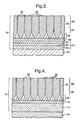
- the thermal barrier coating 32 comprises a bond coating 34 on the superalloy substrate 30, an oxide layer 36 on the bond coating 34 and a ceramic thermal barrier coating 38 on the oxide layer 36.
- the bond coating 34 is generally an aluminium containing alloy for example a MCrAlY alloy where M is at least one of nickel, cobalt or iron, a nickel aluminide, a cobalt aluminide or a platinum aluminide.
- the oxide layer generally comprises alumina together with other oxides.
- the ceramic thermal barrier coating 38 comprises a plurality of columnar ceramic grains 40 which extend substantially perpendicularly to the surface of the superalloy substrate 30. Furthermore it is seen that all of the columnar ceramic grains 40 nucleate on the oxide layer 36 and start to grow substantially perpendicularly to the surface of the superalloy substrate 30.
- the ceramic thermal barrier coating 38 comprises an inner portion 44 on the oxide layer 36, an intermediate portion 46 on the inner portion 44 and an outer portion 48 on the intermediate portion 46.
- the columnar ceramic grains 40 grow competitively in the inner portion 44, but in the intermediate portion 46 the columnar ceramic grains grow 40 progressively less competitively and in the outer portion 48 the columnar ceramic grains 40 grow in a steady state.
- the columnar ceramic grains 40 grow through the full thickness of the ceramic thermal barrier coating 38.
- the columnar ceramic grains 40 remain substantially the same cross-sectional area with increasing distance from the oxide layer 36 in the outer portion 48 of the ceramic thermal barrier coating 38.
- the number of columnar ceramic grains 40 per unit area at the surface of the thermal barrier coating 38 is only slightly less than, preferably substantially the same as, the number of columnar ceramic grains 40 per unit area at the interface between the intermediate portion 46 and the outer portion 48.
- the resistance to spallation of the ceramic thermal barrier coating 38 according to the present invention is better than the prior art ceramic thermal barrier coating particularly at the leading and trailing edge regions of turbine blades and turbine vanes, but also at the pressure and suction surfaces of the turbine vanes and turbine blades.
- columnar ceramic grains 40 with substantially uniform cross-sectional area with increasing distance from the oxide layer 36 in the outer portion 48 and the smooth confronting surfaces on the columnar ceramic grains 40 which reduces, preferably minimises, the internal stress/strain within each of the columnar ceramic grains 40 and/or reduces, preferably minimises, the stress/strain between adjacent columnar ceramic grains 40.
- columnar ceramic grains 20 with increasing cross-sectional area with increasing distance from the oxide layer 16 and the sub-grains projecting transversely from the columnar ceramic grains 20 which produces the greater internal stress/strain within each of the columnar ceramic grains 20 and/or has greater stress/strain between adjacent columnar ceramic grains 20.
- the multi-layer thermal barrier coating 32 is applied on the superalloy article 30 by firstly depositing a MCrAlY alloy bond coating 34 by plasma spraying or physical vapour deposition or forming a nickel aluminide bond coating 34 by diffusion aluminising or forming a platinum aluminide bond coating 34 by platinum modified diffusion aluminising.
- the ceramic thermal barrier coating 38 is then applied onto the bond coating 34 by physical vapour deposition, usually electron beam physical vapour deposition.
- the oxide layer 36 forms on the bond coating 34 while the superalloy article 30 is heated up to the operating temperature in an electron beam physical vapour deposition chamber due to the presence of oxygen.
- the superalloy article 30 is rotated in the electron beam physical vapour deposition chamber in the ceramic vapours to produce the ceramic thermal barrier coating 38.
- the temperature of the superalloy article 30 is maintained at a temperature of 1000°C to 1100°C and the deposition rate of the ceramic on the superalloy article 30 is 3 to 5 micrometers per minute, and the rotation rate of the superalloy article 30 is 15 revolutions per minute.
- the thermal barrier coating 52 comprises a bond coating 54 on the superalloy substrate 50, an oxide layer 56 on the bond coating 54 and a ceramic thermal barrier coating 58 on the oxide layer 56.
- the bond coating 54 is generally an aluminium containing alloy for example a MCrAlY alloy coating 60 where M is at least one of nickel, cobalt or iron, with a platinum enriched MCrAlY layer 62 and a platinum aluminide layer 64 as described more fully in European patent application EP0718419A.
- the oxide layer 56 generally comprises alumina.
- the ceramic thermal barrier coating 58 is similar to that described with reference to figure 2 and again comprises columnar ceramic grains 66.
- the ceramic thermal barrier coating 58 comprises an inner portion 65, an intermediate portion 67 and an outer portion 69.
- the columnar ceramic grains 66 remain substantially the same cross-sectional area throughout the thickness of the outer portion 69.
- the number of columnar ceramic grains 66 per unit area at the surface of the thermal barrier coating 58 is only slightly less than, preferably substantially the same as, the number of columnar ceramic grains 66 per unit area at the interface between the intermediate portion 67 and the outer portion 69.
- the distinct uniform clearances 68 are formed between the columnar ceramic grains 66 and there are no sub-grains projecting transversely from the columnar ceramic grains 66.
- the bond coating 54 is formed by depositing a MCrAlY alloy bond coating, then depositing platinum on the MCrAlY and then heat treating to diffuse the platinum into the MCrAlY.
- the thermal barrier coating 72 comprises a bond coating 74 on the superalloy substrate 70, an oxide layer 76 on the bond coating 74 and a ceramic thermal barrier coating 78 on the oxide layer 76.
- the bond coating 74 is generally a platinum enriched gamma and platinum enriched gamma prime layer on the superalloy as described more fully in European patent application EP0718420A.
- the oxide layer 76 generally comprises alumina.
- the ceramic thermal barrier coating 78 is similar to that described with reference to figure 2 and again comprises columnar ceramic grains 80.
- the ceramic thermal barrier coating 78 comprises an inner portion 84, an intermediate portion 86 and an outer portion 88.
- the columnar ceramic grains 80 remain substantially the same cross-sectional area throughout the thickness of the outer portion 84.
- the number of columnar ceramic grains 80 per unit area at the surface of the thermal barrier coating 78 is only slightly less than, preferably substantially the same as, the number of columnar ceramic grains 80 per unit area at the interface between the intermediate portion 86 and the outer portion 88.
- the distinct uniform clearances 82 are formed between the columnar ceramic grains 80 and there are no sub-grains projecting transversely from the columnar ceramic grains 80.
- the bond coating 74 is formed by depositing platinum on the superalloy and heat treating to diffuse the platinum into the superalloy.
- FIG 5 illustrating a further embodiment of the present invention, there is shown part of a superalloy article 90 provided with a multi-layer thermal barrier coating indicated generally by numeral 92. It is shown in the as manufactured condition.
- the thermal barrier coating 92 comprises a bond coating 94 on the superalloy substrate 90 and a ceramic thermal barrier coating 96 on the bond coating 94.
- the bond coating 94 comprises an oxide layer generally of alumina.
- the ceramic thermal barrier coating 96 is similar to that described with reference to figure 2 and again comprises columnar ceramic grains 98.
- the ceramic thermal barrier coating 96 comprises an inner portion 102, an intermediate portion 104 and an outer portion 106.
- the columnar ceramic grains 98 remain substantially the same cross-sectional area throughout the thickness of the outer portion 106.
- the number of columnar ceramic grains 98 per unit area at the surface of the thermal barrier coating 96 is only slightly less than, preferably substantially the same as, the number of columnar ceramic grains 98 per unit area at the interface between the intermediate portion 104 and the outer portion 106.
- the distinct uniform clearances 100 are formed between the columnar ceramic grains 98 and there are no sub-grains projecting transversely from the columnar ceramic grains 98.
- the bond coating 94 is formed by oxidising the superalloy article 90.
- FIG 6 which shows the average number of hours to spallation of the ceramic thermal barrier coating against speed of rotation of the superalloy article at a constant temperature of 1000°C to 1100°C and at a constant deposition rate of ceramic onto the superalloy article of 3 to 5 micrometers per minute during deposition of the ceramic thermal barrier coating.
- samples of thermal barrier coatings deposited at constant temperature and constant deposition rate but at different rotational speeds were tested for spallation resistance. It is seen that at a rotational speed of 15 revolutions per minute the average number of hours until spallation of the ceramic thermal barrier coating occurs is greatest, for the leading edge, the suction surface and the pressure surface of a turbine blade or a turbine vane.
- Table 1 shows the average hours to spallation at 6 rpm, 15 rpm, 30 rpm and 45 rpm at the leading edge LE, pressure surface PS and suction surface SS of a turbine blade which are also indicated in figure 6.
- the ceramic thermal barrier coatings produced at 6 revolutions per minute and 15 revolutions per minute at a constant temperature of 1000°C to 1100°C and at a constant deposition rate of 3 to 5 micrometers per minute were examined using low voltage scanning electron microscopy to produce micrographs. Three lines were drawn across the micrographs at different levels in the ceramic thermal barrier coating and the average width of the columnar ceramic grains was measured on each line. A first line was drawn at 162 micrometers from the oxide surface, a second line was drawn at 100 micrometers from the oxide surface and a third line was drawn at 54 micrometers from the oxide surface.
- the average width of the columnar ceramic grains in the ceramic thermal barrier coating remains substantially uniform throughout the outer portion of the ceramic thermal barrier coating and the columnar ceramic grains are substantially uniform in cross-sectional area throughout the outer portion of the ceramic thermal barrier coating for distances greater than 100 micrometers from the surface of the bond coating according to the present invention.
- the intermediate portion and inner portion are at distances less than 100 micrometers from the surface of the alumina.
- the interface between the intermediate portion and the outer portion is between 54 and 100 micrometers and thus is between 33% and 62% of the thickness of the ceramic thermal barrier coating.
- the outer portion is therefore between 38% and 67% of the thickness of the ceramic thermal barrier coating.
- the average widths of the columnar ceramic grains increases at the rate of 0.24 micrometers per 100 micrometer length of the columnar ceramic grain between 100 and 162 micrometers from the surface of the bond coating for the ceramic thermal barrier coating deposited at 15 rpm.
- the average width of the columnar ceramic grains increases at the rate of 2.5 micrometers per 100 micrometer length of the columnar ceramic grain between 100 and 162 micrometers from the surface of the bond coating for the ceramic thermal barrier coating deposited at 6 rpm.
- the rate of increase of the widths of the columnar ceramic grains is between nine and ten times more for the ceramic thermal barrier coating deposited at 6 rpm than those deposited at 15 rpm between 100 and 160 micrometers from the surface of the substrate.
- the pressure and suction surfaces of turbine blades coated with ceramic thermal barrier coatings deposited at 6 rpm and 15 rpm were examined by X-ray diffraction to determine the width of the X-ray diffraction peaks.
- the width of the X-ray diffraction peaks is an indication of the strain within the structure of the ceramic thermal barrier coatings. The greater the width of the X-ray diffraction peak the greater the strain.
- FIG 7 which shows the minimum and maximum number of hours to spallation of the ceramic thermal barrier coating against speed of rotation of the superalloy article at a constant temperature of 1000°C to 1100°C and at a constant deposition rate of ceramic onto the superalloy article of 3 to 5 micrometers per minute during deposition of the ceramic thermal barrier coating.
- MAR-M002 superalloy turbine blades were provided with a platinum aluminide bond coating by platinum aluminising and an oxide was formed on the platinum aluminide.
- Samples of thermal barrier coatings were deposited at constant temperature and constant deposition rate but at different rotational speeds. These were tested for spallation resistance at the leading edges.
- the average width of the columnar ceramic grains on the suction surface (SS) of the ceramic thermal barrier coating at 50, 100, 150 and 200 micrometers from the surface of the substrate were measured for ceramic thermal barrier coatings deposited at 6 rpm and 15 rpm and these are shown in Table 5.
- the average width of the columnar ceramic grains in the ceramic thermal barrier coating remains substantially uniform throughout the outer portion of the ceramic thermal barrier coating and the columnar ceramic grains are substantially uniform in cross-sectional area throughout the outer portion of the ceramic thermal barrier coating for distances greater than 150 micrometers from the surface of the bond coating according to the present invention.
- the intermediate portion and inner portion are at distances less than 150 micrometers from the surface of the alumina.
- the interface between the intermediate portion and the outer portion is between 100 and 150 micrometers and thus is between 40% and 60% of the thickness of the ceramic thermal barrier coating.
- the outer portion is therefore between 40% and 60% of the thickness of the ceramic thermal barrier coating.
- the average width of the columnar ceramic grains increases at the rate of 1.7 micrometers per 100 micrometer length of the columnar ceramic grain between 150 and 250 micrometers from the surface of the substrate for the ceramic thermal barrier coating deposited at 15 rpm.
- the average width of the columnar ceramic grains increases at the rate of 6.44 micrometers per 100 micrometer length of the columnar ceramic grain between 150 and 200 micrometers from the surface of the substrate for the ceramic thermal barrier coating deposited at 6 rpm.
- the rate of increase of the widths of the columnar ceramic grains is between three and four times more for the ceramic thermal barrier coating deposited at 6 rpm than those deposited at 15 rpm between 150 and 200 micrometers from the surface of the substrate.
- Figure 8 is a graph showing the widths of the columnar ceramic grains with increasing distances from the surface of the alumina.
- Line X indicates the columnar ceramic grains according to the present invention and line Y indicates the columnar ceramic grains according to the prior art.
- columnar ceramic grains which have substantially uniform cross-sectional area throughout their lengths in the outer portion of the ceramic thermal barrier coating, which have smooth surfaces and which have uniform clearances with adjacent columnar ceramic grains to minimise stress/strain to increase spallation resistance of the ceramic thermal barrier coating.
- This may be achieved by controlling the temperature of the article, the evaporation rate of the ceramic and the speed of rotation of the article.
- the above example has shown that by maintaining evaporation rate and temperature constant the speed of rotation should be adjusted until the required columnar ceramic grain structure is achieved. It may be equally possible to obtain the same columnar ceramic grain structure by maintaining the evaporation rate and speed of rotation constant and adjusting the temperature or by maintaining the temperature and speed of rotation constant and adjusting the evaporation rate.
- the temperature of the article or component, the rate of arrival of ceramic onto the article or component and the rate of rotation of the article or component are balanced such that the columnar ceramic grains grow with a uniform cross-sectional area throughout their lengths, with smooth surfaces and with distinct uniform clearances between adjacent columnar ceramic grains.
- the rate of arrival of ceramic is called the deposition rate.
- the rate of arrival is determined by the evaporation rate of the ceramic.
- the average width of the columnar ceramic grains may vary depending on the position on the surface of the metallic article. In the case of a metallic turbine blade, or metallic turbine vane, the columnar ceramic grains have the greatest width at the leading edge, the smallest width on the pressure surface and an intermediate width on the suction surface.
Landscapes
- Chemical & Material Sciences (AREA)
- Engineering & Computer Science (AREA)
- Metallurgy (AREA)
- Chemical Kinetics & Catalysis (AREA)
- Materials Engineering (AREA)
- Mechanical Engineering (AREA)
- Inorganic Chemistry (AREA)
- Organic Chemistry (AREA)
- Ceramic Engineering (AREA)
- Turbine Rotor Nozzle Sealing (AREA)
- Physical Vapour Deposition (AREA)
- Other Surface Treatments For Metallic Materials (AREA)
- Laminated Bodies (AREA)
Claims (25)
- Metallischer Gegenstand (30) mit einem Verbundüberzug (34) auf dem metallischen Gegenstand (30) und mit einem keramischen Wärmesperrüberzug (38) auf dem Verbundüberzug (34), wobei der keramische Wärmesperrüberzug (38) eine Vielzahl von Stengelkörnern (40) aufweist, die sich im wesentlichen senkrecht. zur Oberfläche des metallischen Gegenstandes (30) erstrecken und wobei der keramische Wärmesperrüberzug (38) einen inneren Abschnitt (44) benachbart zum Verbundüberzug (34), einen Zwischenabschnitt (46) auf dem inneren Abschnitt (44) und einen äußeren Abschnitt (48) auf dem Zwischenabschnitt (46) aufweist und der innere Abschnitt (44) Stengelkömer (40) aufweist, deren Querschnittsfläche sich mit zunehmendem Abstand von der Oberfläche des metallischen Gegenstandes (30) vergrößert und Stengelkörner in unterschiedlichen Abständen von der Oberfläche des metallischen Gegenstandes (30) durch andere Stengelkörner blockiert sind,
dadurch gekennzeichnet, daß in dem äußeren Abschnitt (48) jedes Stengelkorn (40) über seine Länge eine im wesentlichen konstante Querschnittsfläche aufweist und jedes Stengelkorn (40) glatte Außenseiten besitzt, ohne daß von diesen Subkörner vorstehen und daß jedes Stengelkorn (40) von benachbarten Stengelkörnern (40) durch einen gleichförmigen Zwischenraum (42) getrennt ist, um die Spannung/Beanspruchung in den Stengelkörnern (40) zu vermindern und/oder um die Spannung/Beanspruchung zwischen benachbarten Stengelkörnern (40) zu vermindern und um dadurch den Widerstand gegenüber einem Abblättern des keramischen Wärmesperrüberzugs (38) zu erhöhen. - Metallischer Gegenstand nach Anspruch 1, bei welchem der Verbundüberzug (34) ein Aluminium enthaltender Verbundüberzug (34) auf dem metallischen Gegenstand (30) ist und der Aluminium enthaltende Verbundüberzug (34) eine Aluminiumoxid-Oberflächenschicht (36) besitzt und der keramische Wärmesperrüberzug (38) auf der Aluminiumoxidschicht (36) angeordnet ist.
- Metallischer Gegenstand nach Anspruch 2, bei welchem der Aluminium enthaltende Verbundüberzug (34) einen MCrAIY-Verbundüberzug (wobei M wenigstens eines der Elemente Kobalt, Eisen und Nickel ist), einen Aluminidüberzug oder einen Platin-Aluminid-Überzug aufweist.
- Metallischer Gegenstand nach Anspruch 1, bei welchem der Verbundüberzug einen MCrAlY-Verbundüberzug (60) (wobei M wenigstens eines der Elemente Kobalt, Eisen und Nickel ist) auf dem metallischen Gegenstand (50), eine mit Platin angereicherte MCrAlY-Schicht (62) auf dem MCrAlY-Verbundüberzug (60) und eine Platin-Aluminid-Schicht (64) auf der mit Platin angereicherten MCrAlY-Schicht (62) aufweist, wobei die Platin-Aluminid-Schicht (64) eine Aluminiumoxidschicht (56) aufweist und der keramische Wärmesperrüberzug (58) auf der Aluminiumoxidschicht (56) angeordnet ist.
- Metallischer Gegenstand nach Anspruch 1, bei welchem der metallische Gegenstand (90) eine Aluminiumoxidschicht (94) aufweist und der keramische Wärmesperrüberzug (96) auf der Aluminiumoxidschicht (94) angeordnet ist.
- Metallischer Gegenstand nach einem der Ansprüche 1 bis 5, bei welchem der metallische Gegenstand (30) ein Nickel-Superlegierungs-Gegenstand oder ein Kobalt-Superlegierungs-Gegenstand ist.
- Metallischer Gegenstand nach einem der Ansprüche 1 bis 6, bei der der metallische Gegenstand (30) eine Turbinenlaufschaufel oder eine Turbinenleitschaufel ist.
- Metallischer Gegenstand nach einem der Ansprüche 1 bis 7, bei welchem der keramische Wärmesperrüberzug (38) Zirkonoxid enthält.
- Metallischer Gegenstand nach Anspruch 8, bei welchem das Zirkonoxid mit Yttriumoxid stabilisiert ist.
- Metallischer Gegenstand nach einem der Ansprüche 1 bis 9, bei welchem der äußere Abschnitt (48) zwischen 38% und 67% der Dicke des keramischen Wärmesperrüberzugs (38) aufweist.
- Metallischer Gegenstand nach Anspruch 10, bei welchem der äußere Abschnitt (48) zwischen 40% und 60% der Dicke des keramischen Wärmesperrüberzugs (38) aufweist.
- Metallischer Gegenstand nach einem der Ansprüche 1 bis 11, bei welchem die Breite der keramischen Stengelkörner (40) im äußeren Abschnitt (48) mit einer Rate ansteigt, die gleich oder geringer ist als 2,0 µm pro 100 µm Länge der keramischen Stengelkörner (40).
- Metallischer Gegenstand nach Anspruch 12, bei welchem die Breite der keramischen Stengelkömer (40) im äußeren Abschnitt (48) mit einer Rate ansteigt, die gleich oder geringer ist als 1,7 µm pro 100 µm Länge der keramischen Stengelkömer (40).
- Metallischer Gegenstand nach Anspruch 13, bei welchem die Breite der keramischen Stengelkörner (40) im äußeren Abschnitt (48) mit einer Rate ansteigt, die gleich oder geringer ist als 0,24 Am pro 100 µm Länge der keramischen Stengelkörner (40).
- Verfahren zum Aufbringen eines keramischen Wärmesperrüberzugs (38) auf einem metallischen Gegenstand (30) mit den folgenden Schritten: es wird ein Verbundüberzug (34) auf dem metallischen Gegenstand (30) ausgebildet; es wird ein keramischer Wärmesperrüberzug (38) auf dem Verbundüberzug (34) durch Dampfablagerung aufgetragen, um eine Vielzahl von Stengelkörnern (40) zu erzeugen, die sich im wesentlichen senkrecht zur Oberfläche des metallischen Gegenstandes (30) erstrecken,
dadurch gekennzeichnet, daß die Dampfablagerung des keramischen Wärmesperrüberzugs (38) die folgenden Schritte umfaßt: es wird ein innerer Abschnitt (44) benachbart zum Verbundüberzug (34) aufgetragen; es wird ein Zwischenabschnitt (46) auf dem inneren Abschnitt (44) aufgetragen und es wird ein äußerer Abschnitt (48) auf dem Zwischenabschnitt (46) aufgetragen, wobei der innere Abschnitt (44) Stengelkömer (40) aufweist, deren Querschnittsfläche sich mit zunehmendem Abstand von der Oberfläche des metallischen Gegenstandes (30) vergrößert und die Stengelkörner in verschiedenen Abständen von der Oberfläche des metallischen Gegenstandes (30) durch die anderen Stengelkörner blockiert sind,
dadurch gekennzeichnet, daß das Verfahren die folgenden Schritte umfaßt: es wird die Rate der Verdampfung des Keramikmaterials, die Temperatur des metallischen Gegenstandes (30) und die Drehzahl des metallischen Gegenstandes (30) während der Dampfablagerung des keramischen Wärmesperrüberzugs (38) eingestellt, wobei die Verdampfungsrate des Keramikmaterials 3 bis 5 µm pro Minute beträgt, die Temperatur des metallischen Gegenstandes (30) 1000°C bis 1100°C beträgt und die Drehzahl des metallischen Gegenstandes (30) 15 u/min aufweist und in dem äußeren Abschnitt (48) jedes Stengelkorn (40) eine im wesentlichen konstante Querschnittsfläche über die gesamte Länge aufweist und jedes Stengelkorn (40) glatte Seiten ohne vorstehende Subkörner besitzt und jedes Stengelkorn (40) von den benachbarten Stengelkörnern (40) durch gleichförmige Zwischenräume (42) getrennt ist, um die Spannung/Beanspruchung in dem Stengelkorn (40) zu vermindern und/oder die Spannung/Beanspruchung zwischen benachbarten Stengelkörnern (40) zu vermindern und um dadurch den Widerstand des keramischen Wärmesperrüberzugs (38) gegen Abblätterung zu erhöhen. - Verfahren nach Anspruch 15, bei welchem ein Aluminium enthaltender Verbundüberzug (34) auf dem metallischen Gegenstand (30) aufgebracht wird und eine Aluminiumoxidschicht (36) auf dem Aluminium enthaltenden Verbundüberzug (34) aufgebracht wird.
- Verfahren nach Anspruch 16, bei welchem der Aluminium enthaltende Verbundüberzug (34) aus einer MCrAlY-Legierung besteht, wobei M wenigstens Kobalt und/oder Eisen und/oder Nickel und ein Aluminid oder ein Platin-Aluminid ist.
- Verfahren nach Anspruch 15, bei welchem ein MCrAlY-Verbundüberzug (60) auf dem metallischen Gegenstand (50) aufgebracht wird und M wenigstens eines der Elemente Kobalt, Eisen und Nickel enthält und eine mit Platin angereicherte MCrAlY-Schicht (62) auf dem MCrAlY-Verbundüberzug (60) aufgebracht wird und bei dem eine Platin-Aluminid-Schicht (64) auf der mit Platin angereicherten MCrAlY-Schicht (62) ausgebildet wird und eine Aluminiumoxid-Oberflächenschicht (56) auf der Platin-Aluminid-Schicht (64) ausgebildet wird.
- Verfahren nach Anspruch 15, bei welchem eine Aluminiumoxid-Oberflächenschicht (94) auf dem metallischen Gegenstand (90) ausgebildet wird.
- Verfahren nach einem der Ansprüche 15 bis 19, bei welchem der metallische Gegenstand (30) aus einer Nickel-Superlegierung oder einer Kobalt-Superlegierung hergestellt ist.
- Verfahren nach einem der Ansprüche 15 bis 20, bei welchem der metallische Gegenstand (30) eine Turbinenlaufschaufel oder eine Turbinenleitschaufel ist.
- Verfahren nach einem der Ansprüche 15 bis 21, bei welchem der keramische Wärmesperrüberzug (38) Zirkonoxid enthält.
- Verfahren nach Anspruch 22, bei welchem das Zirkonoxid mit Yttriumoxid stabilisiert ist.
- Verfahren nach einem der Ansprüche 15 bis 23, bei welchem der keramische Wärmesperrüberzug (38) durch physikalische Dampfablagerung aufgetragen wird.
- Verfahren nach Anspruch 24, bei welchem der keramische Wärmesperrüberzug (38) durch physikalische Elektronenstrahl-Dampfablagerung aufgetragen wird.
Applications Claiming Priority (2)
| Application Number | Priority Date | Filing Date | Title |
|---|---|---|---|
| GB9811456 | 1998-05-29 | ||
| GBGB9811456.4A GB9811456D0 (en) | 1998-05-29 | 1998-05-29 | A metallic article having a thermal barrier coating and a method of application thereof |
Publications (3)
| Publication Number | Publication Date |
|---|---|
| EP0964077A2 EP0964077A2 (de) | 1999-12-15 |
| EP0964077A3 EP0964077A3 (de) | 2000-01-12 |
| EP0964077B1 true EP0964077B1 (de) | 2003-06-25 |
Family
ID=10832839
Family Applications (1)
| Application Number | Title | Priority Date | Filing Date |
|---|---|---|---|
| EP99303864A Revoked EP0964077B1 (de) | 1998-05-29 | 1999-05-18 | Metallischer Artikel mit einer Wärmesperrschicht und Verfahren zur Anwendung desselben |
Country Status (9)
| Country | Link |
|---|---|
| US (1) | US6221512B1 (de) |
| EP (1) | EP0964077B1 (de) |
| JP (1) | JP2000026950A (de) |
| CA (1) | CA2272815A1 (de) |
| DE (1) | DE69909022T2 (de) |
| GB (1) | GB9811456D0 (de) |
| IL (1) | IL130141A0 (de) |
| RU (1) | RU2216606C2 (de) |
| UA (1) | UA65548C2 (de) |
Families Citing this family (17)
| Publication number | Priority date | Publication date | Assignee | Title |
|---|---|---|---|---|
| US6641907B1 (en) * | 1999-12-20 | 2003-11-04 | Siemens Westinghouse Power Corporation | High temperature erosion resistant coating and material containing compacted hollow geometric shapes |
| US7150922B2 (en) * | 2000-03-13 | 2006-12-19 | General Electric Company | Beta-phase nickel aluminide overlay coatings and process therefor |
| US6340500B1 (en) * | 2000-05-11 | 2002-01-22 | General Electric Company | Thermal barrier coating system with improved aluminide bond coat and method therefor |
| US6689487B2 (en) * | 2001-12-21 | 2004-02-10 | Howmet Research Corporation | Thermal barrier coating |
| US6720038B2 (en) * | 2002-02-11 | 2004-04-13 | General Electric Company | Method of forming a coating resistant to deposits and coating formed thereby |
| US6887529B2 (en) * | 2003-04-02 | 2005-05-03 | General Electric Company | Method of applying environmental and bond coatings to turbine flowpath parts |
| US7390535B2 (en) | 2003-07-03 | 2008-06-24 | Aeromet Technologies, Inc. | Simple chemical vapor deposition system and methods for depositing multiple-metal aluminide coatings |
| FR2870858B1 (fr) * | 2004-05-28 | 2007-04-06 | Snecma Moteurs Sa | Procede de fabrication ou de reparation d'un revetement sur un substrat metallique |
| EP1783248A1 (de) * | 2005-11-04 | 2007-05-09 | Siemens Aktiengesellschaft | Zweilagiges thermisches Schutzschichtsystem mit Pyrochlor-Phase |
| US20070138019A1 (en) * | 2005-12-21 | 2007-06-21 | United Technologies Corporation | Platinum modified NiCoCrAlY bondcoat for thermal barrier coating |
| US7918141B1 (en) | 2007-04-03 | 2011-04-05 | The United States Of America As Represented By The Secretary Of The Air Force | Local residual stress measurement and analysis for detection and prediction of damage in thermal barrier coatings |
| US8206829B2 (en) * | 2008-11-10 | 2012-06-26 | Applied Materials, Inc. | Plasma resistant coatings for plasma chamber components |
| US8807955B2 (en) * | 2011-06-30 | 2014-08-19 | United Technologies Corporation | Abrasive airfoil tip |
| WO2015108747A1 (en) | 2014-01-20 | 2015-07-23 | United Technologies Corporation | Physical vapor deposition using rotational speed selected with respect to deposition rate |
| GB201416585D0 (en) * | 2014-09-19 | 2014-11-05 | Rolls Royce Plc | A method of applying a thermal barrier coating to a metallic article and a thermal barrier coated metallic article |
| GB201903484D0 (en) | 2019-03-14 | 2019-05-01 | Rolls Royce Plc | A method of removing a ceramic coating from a ceramic coated metallic article |
| US11686208B2 (en) | 2020-02-06 | 2023-06-27 | Rolls-Royce Corporation | Abrasive coating for high-temperature mechanical systems |
Citations (1)
| Publication number | Priority date | Publication date | Assignee | Title |
|---|---|---|---|---|
| EP0937787A1 (de) * | 1998-02-19 | 1999-08-25 | United Technologies Corporation | Verfahren zur Beschichtung eines thermischen Sperrschichtsystems, sowie beschichteter Gegenstand |
Family Cites Families (20)
| Publication number | Priority date | Publication date | Assignee | Title |
|---|---|---|---|---|
| SU533672A1 (ru) * | 1974-12-17 | 1976-10-30 | Предприятие П/Я А-1857 | Способ получени покрытий из тугоплавких металлов и их карбидов |
| IT1087793B (it) * | 1976-12-11 | 1985-06-04 | Glyco Metall Werke | Materiale stratificato e procedimento per la sua fabbricazione per mezzo della placcatura termocinetica |
| GB2025469A (en) * | 1978-07-17 | 1980-01-23 | United Technologies Corp | Plasma sprayed MCrAlY coatings |
| US4321310A (en) | 1980-01-07 | 1982-03-23 | United Technologies Corporation | Columnar grain ceramic thermal barrier coatings on polished substrates |
| US4321311A (en) | 1980-01-07 | 1982-03-23 | United Technologies Corporation | Columnar grain ceramic thermal barrier coatings |
| FR2526445A1 (fr) * | 1982-05-05 | 1983-11-10 | Penarroya Miniere Metall | Procede et alliage de galvanisation au trempe d'acier et objet galvanise |
| US4676994A (en) | 1983-06-15 | 1987-06-30 | The Boc Group, Inc. | Adherent ceramic coatings |
| US5514482A (en) * | 1984-04-25 | 1996-05-07 | Alliedsignal Inc. | Thermal barrier coating system for superalloy components |
| US5073433B1 (en) * | 1989-10-20 | 1995-10-31 | Praxair Technology Inc | Thermal barrier coating for substrates and process for producing it |
| JP2729289B2 (ja) * | 1990-08-08 | 1998-03-18 | アドヴァンスト・セラミックス・コーポレイション | 亀裂のない熱分解窒化硼素を炭素構造体上に形成する方法及び該方法から得られた物品 |
| GB9204791D0 (en) | 1992-03-05 | 1992-04-22 | Rolls Royce Plc | A coated article |
| RU2064526C1 (ru) * | 1992-09-28 | 1996-07-27 | Всероссийский научно-исследовательский и проектный институт тугоплавких металлов и твердых сплавов - Завод "Победит" | Способ получения композиционного слоистого материала на основе твердого сплава |
| US5350599A (en) | 1992-10-27 | 1994-09-27 | General Electric Company | Erosion-resistant thermal barrier coating |
| GB9222594D0 (en) * | 1992-10-27 | 1992-12-16 | British Petroleum Co | Coated filaments |
| DE4334818A1 (de) * | 1993-03-10 | 1994-09-15 | Sintec Keramik Gmbh | Verfahren zur Herstellung von hochreinen, spannungsfreien interfraktionären Metallbeschichtungen oder Formkörper |
| US5596813A (en) * | 1994-08-30 | 1997-01-28 | Saint Gobain/Norton Industrial Ceramics Corp. | Measuring instrument with diamond coated contacts |
| EP0718420B1 (de) * | 1994-12-24 | 1999-04-21 | Rolls Royce Plc | Wärmedämmschicht sowie Methode zu deren Auftragung auf einen Superlegierungskörper |
| GB9426257D0 (en) * | 1994-12-24 | 1995-03-01 | Rolls Royce Plc | Thermal barrier coating for a superalloy article and method of application |
| US5716720A (en) | 1995-03-21 | 1998-02-10 | Howmet Corporation | Thermal barrier coating system with intermediate phase bondcoat |
| US5512382A (en) | 1995-05-08 | 1996-04-30 | Alliedsignal Inc. | Porous thermal barrier coating |
-
1998
- 1998-05-29 GB GBGB9811456.4A patent/GB9811456D0/en not_active Ceased
-
1999
- 1999-05-18 EP EP99303864A patent/EP0964077B1/de not_active Revoked
- 1999-05-18 DE DE69909022T patent/DE69909022T2/de not_active Revoked
- 1999-05-19 US US09/314,029 patent/US6221512B1/en not_active Expired - Lifetime
- 1999-05-26 UA UA99052932A patent/UA65548C2/uk unknown
- 1999-05-26 IL IL13014199A patent/IL130141A0/xx not_active IP Right Cessation
- 1999-05-26 CA CA002272815A patent/CA2272815A1/en not_active Abandoned
- 1999-05-28 RU RU99111082/02A patent/RU2216606C2/ru not_active IP Right Cessation
- 1999-05-31 JP JP11152216A patent/JP2000026950A/ja active Pending
Patent Citations (1)
| Publication number | Priority date | Publication date | Assignee | Title |
|---|---|---|---|---|
| EP0937787A1 (de) * | 1998-02-19 | 1999-08-25 | United Technologies Corporation | Verfahren zur Beschichtung eines thermischen Sperrschichtsystems, sowie beschichteter Gegenstand |
Also Published As
| Publication number | Publication date |
|---|---|
| EP0964077A2 (de) | 1999-12-15 |
| DE69909022T2 (de) | 2004-07-08 |
| DE69909022D1 (de) | 2003-07-31 |
| IL130141A0 (en) | 2000-06-01 |
| EP0964077A3 (de) | 2000-01-12 |
| US6221512B1 (en) | 2001-04-24 |
| JP2000026950A (ja) | 2000-01-25 |
| CA2272815A1 (en) | 1999-11-29 |
| UA65548C2 (en) | 2004-04-15 |
| GB9811456D0 (en) | 1998-07-29 |
| RU2216606C2 (ru) | 2003-11-20 |
Similar Documents
| Publication | Publication Date | Title |
|---|---|---|
| EP0940480B1 (de) | Metallischer Artikel mit einer wärmedämmenden Beschichtung und Verfahren zum Aufbringen derselben | |
| US6221512B1 (en) | Metallic article having a thermal barrier coating and a method of application thereof | |
| JP3825114B2 (ja) | 粒状物によるエロージョン及び衝撃に対して耐性の断熱皮膜 | |
| EP1536040B1 (de) | Verstärkte Bindungsschicht für eine Wärmedämmschicht | |
| EP1254967B1 (de) | Verbessertes plasmagespritztes Wärmedämmhaftungsschichtsystem | |
| EP0979881B1 (de) | Wärmedämmendes Beschichtungssystem und Überzug mit einer Metall/Metalloxyd-Haftbeschichtigung | |
| US7285312B2 (en) | Atomic layer deposition for turbine components | |
| US5350599A (en) | Erosion-resistant thermal barrier coating | |
| EP1109948B1 (de) | Mehrschichtige wärmedämmende beschichtungssysteme | |
| US6382920B1 (en) | Article with thermal barrier coating and method of producing a thermal barrier coating | |
| US6572981B2 (en) | Thermal barrier coating system with improved aluminide bond coat and method therefor | |
| EP2258889B1 (de) | Verfahren und Vorrichtung zum Auftragen einer Wärmedämmbeschichtung | |
| EP1411210A1 (de) | Verfahren zur Abscheidung einer ermüdungs- und oxydationsbeständigen MCrAlY-Beschichtung | |
| US6482469B1 (en) | Method of forming an improved aluminide bond coat for a thermal barrier coating system | |
| EP1120480B1 (de) | Verbessertes Beschichtungssystem für Turbinenschaufeln | |
| EP1411148A1 (de) | Verfahren zur MCrAlY-Haftungsbeschichtung auf einen beschichteten Gegenstand und beschichteter Gegenstand | |
| EP1686199B1 (de) | Wärmedämmschicht | |
| EP0985745A1 (de) | Haftbeschichtung für wärmedämmendes Beschichtungssystem | |
| EP2998417B1 (de) | Verfahren zum auftragen einer wärmesperre auf ein metallischer gegenstand | |
| US6663983B1 (en) | Thermal barrier coating with improved strength and fracture toughness | |
| US20250243770A1 (en) | Internal aluminide coating for vanes and blades and method of manufacture | |
| EP1491659B1 (de) | Verfahren für das Auftragen eines mehrschichtigen Systems | |
| EP1491650B1 (de) | Verfahren für das Auftragen eines mehrschichtigen Systems | |
| EP4700148A1 (de) | Verfahren zum beschichten eines teils mit variabler dicke |
Legal Events
| Date | Code | Title | Description |
|---|---|---|---|
| PUAI | Public reference made under article 153(3) epc to a published international application that has entered the european phase |
Free format text: ORIGINAL CODE: 0009012 |
|
| PUAL | Search report despatched |
Free format text: ORIGINAL CODE: 0009013 |
|
| AK | Designated contracting states |
Kind code of ref document: A2 Designated state(s): BE DE FR GB IT NL |
|
| AX | Request for extension of the european patent |
Free format text: AL;LT;LV;MK;RO;SI |
|
| AK | Designated contracting states |
Kind code of ref document: A3 Designated state(s): AT BE CH CY DE DK ES FI FR GB GR IE IT LI LU MC NL PT SE |
|
| AX | Request for extension of the european patent |
Free format text: AL;LT;LV;MK;RO;SI |
|
| 17P | Request for examination filed |
Effective date: 20000208 |
|
| AKX | Designation fees paid |
Free format text: BE DE FR GB IT NL |
|
| 17Q | First examination report despatched |
Effective date: 20010809 |
|
| GRAH | Despatch of communication of intention to grant a patent |
Free format text: ORIGINAL CODE: EPIDOS IGRA |
|
| GRAH | Despatch of communication of intention to grant a patent |
Free format text: ORIGINAL CODE: EPIDOS IGRA |
|
| GRAA | (expected) grant |
Free format text: ORIGINAL CODE: 0009210 |
|
| AK | Designated contracting states |
Designated state(s): BE DE FR GB IT NL |
|
| REG | Reference to a national code |
Ref country code: GB Ref legal event code: FG4D |
|
| REF | Corresponds to: |
Ref document number: 69909022 Country of ref document: DE Date of ref document: 20030731 Kind code of ref document: P |
|
| ET | Fr: translation filed | ||
| PLBI | Opposition filed |
Free format text: ORIGINAL CODE: 0009260 |
|
| 26 | Opposition filed |
Opponent name: SIEMENS AG Effective date: 20040206 |
|
| PLAX | Notice of opposition and request to file observation + time limit sent |
Free format text: ORIGINAL CODE: EPIDOSNOBS2 |
|
| NLR1 | Nl: opposition has been filed with the epo |
Opponent name: SIEMENS AG |
|
| PLBB | Reply of patent proprietor to notice(s) of opposition received |
Free format text: ORIGINAL CODE: EPIDOSNOBS3 |
|
| PGFP | Annual fee paid to national office [announced via postgrant information from national office to epo] |
Ref country code: FR Payment date: 20050411 Year of fee payment: 7 |
|
| PGFP | Annual fee paid to national office [announced via postgrant information from national office to epo] |
Ref country code: NL Payment date: 20050413 Year of fee payment: 7 Ref country code: GB Payment date: 20050413 Year of fee payment: 7 |
|
| PGFP | Annual fee paid to national office [announced via postgrant information from national office to epo] |
Ref country code: DE Payment date: 20050415 Year of fee payment: 7 |
|
| PGFP | Annual fee paid to national office [announced via postgrant information from national office to epo] |
Ref country code: BE Payment date: 20050511 Year of fee payment: 7 |
|
| RDAF | Communication despatched that patent is revoked |
Free format text: ORIGINAL CODE: EPIDOSNREV1 |
|
| RDAD | Information modified related to despatch of communication that patent is revoked |
Free format text: ORIGINAL CODE: EPIDOSCREV1 |
|
| RDAG | Patent revoked |
Free format text: ORIGINAL CODE: 0009271 |
|
| STAA | Information on the status of an ep patent application or granted ep patent |
Free format text: STATUS: PATENT REVOKED |
|
| 27W | Patent revoked |
Effective date: 20050916 |
|
| GBPR | Gb: patent revoked under art. 102 of the ep convention designating the uk as contracting state |
Free format text: 20050916 |
|
| NLR2 | Nl: decision of opposition |
Effective date: 20050916 |
|
| PLAB | Opposition data, opponent's data or that of the opponent's representative modified |
Free format text: ORIGINAL CODE: 0009299OPPO |
|
| PGFP | Annual fee paid to national office [announced via postgrant information from national office to epo] |
Ref country code: IT Payment date: 20100524 Year of fee payment: 12 |