EP0963235B1 - Open contact reactor - Google Patents
Open contact reactor Download PDFInfo
- Publication number
- EP0963235B1 EP0963235B1 EP98903327A EP98903327A EP0963235B1 EP 0963235 B1 EP0963235 B1 EP 0963235B1 EP 98903327 A EP98903327 A EP 98903327A EP 98903327 A EP98903327 A EP 98903327A EP 0963235 B1 EP0963235 B1 EP 0963235B1
- Authority
- EP
- European Patent Office
- Prior art keywords
- tank
- wall
- gas flow
- levels
- flow direction
- Prior art date
- Legal status (The legal status is an assumption and is not a legal conclusion. Google has not performed a legal analysis and makes no representation as to the accuracy of the status listed.)
- Expired - Lifetime
Links
- 239000007921 spray Substances 0.000 claims abstract description 15
- 239000007788 liquid Substances 0.000 claims abstract description 12
- 238000005507 spraying Methods 0.000 claims abstract description 4
- 239000007789 gas Substances 0.000 description 28
- 238000000034 method Methods 0.000 description 5
- 238000004140 cleaning Methods 0.000 description 3
- 239000003344 environmental pollutant Substances 0.000 description 3
- 231100000719 pollutant Toxicity 0.000 description 3
- 238000001816 cooling Methods 0.000 description 2
- 238000010438 heat treatment Methods 0.000 description 2
- 230000002745 absorbent Effects 0.000 description 1
- 239000002250 absorbent Substances 0.000 description 1
- 230000002349 favourable effect Effects 0.000 description 1
- 238000009827 uniform distribution Methods 0.000 description 1
- XLYOFNOQVPJJNP-UHFFFAOYSA-N water Substances O XLYOFNOQVPJJNP-UHFFFAOYSA-N 0.000 description 1
Images
Classifications
-
- B—PERFORMING OPERATIONS; TRANSPORTING
- B01—PHYSICAL OR CHEMICAL PROCESSES OR APPARATUS IN GENERAL
- B01D—SEPARATION
- B01D53/00—Separation of gases or vapours; Recovering vapours of volatile solvents from gases; Chemical or biological purification of waste gases, e.g. engine exhaust gases, smoke, fumes, flue gases, aerosols
- B01D53/34—Chemical or biological purification of waste gases
- B01D53/74—General processes for purification of waste gases; Apparatus or devices specially adapted therefor
- B01D53/77—Liquid phase processes
- B01D53/78—Liquid phase processes with gas-liquid contact
-
- B—PERFORMING OPERATIONS; TRANSPORTING
- B01—PHYSICAL OR CHEMICAL PROCESSES OR APPARATUS IN GENERAL
- B01D—SEPARATION
- B01D47/00—Separating dispersed particles from gases, air or vapours by liquid as separating agent
- B01D47/06—Spray cleaning
-
- B—PERFORMING OPERATIONS; TRANSPORTING
- B01—PHYSICAL OR CHEMICAL PROCESSES OR APPARATUS IN GENERAL
- B01D—SEPARATION
- B01D53/00—Separation of gases or vapours; Recovering vapours of volatile solvents from gases; Chemical or biological purification of waste gases, e.g. engine exhaust gases, smoke, fumes, flue gases, aerosols
- B01D53/14—Separation of gases or vapours; Recovering vapours of volatile solvents from gases; Chemical or biological purification of waste gases, e.g. engine exhaust gases, smoke, fumes, flue gases, aerosols by absorption
- B01D53/18—Absorbing units; Liquid distributors therefor
- B01D53/185—Liquid distributors
-
- F—MECHANICAL ENGINEERING; LIGHTING; HEATING; WEAPONS; BLASTING
- F28—HEAT EXCHANGE IN GENERAL
- F28C—HEAT-EXCHANGE APPARATUS, NOT PROVIDED FOR IN ANOTHER SUBCLASS, IN WHICH THE HEAT-EXCHANGE MEDIA COME INTO DIRECT CONTACT WITHOUT CHEMICAL INTERACTION
- F28C3/00—Other direct-contact heat-exchange apparatus
- F28C3/06—Other direct-contact heat-exchange apparatus the heat-exchange media being a liquid and a gas or vapour
Definitions
- the present invention relates to an open contact reactor being in the form of a tank, in which a plurality of spray nozzles for spraying finely divided liquid are arranged and through which a gas is to be conducted in a main gas flow direction in order to be contacted with the finely divided liquid, the spray nozzles being arranged on different nozzle levels which are spaced apart in the main gas flow direction, and the nozzles on each level being substantially uniformly distributed over the cross-section of the tank.
- Reactors of this type are used for various purposes. For instance, they can be used for cleaning of process gases containing gaseous pollutants, and for cooling/heating of gases. In these two applications, it seems possible to improve the efficiency of the reactor, i.e. increase the capacity of the reactor of respectively cleaning and cooling/heating the gases.
- the object of the present invention therefore is to provide an open contact reactor, which has an improved efficiency in relation to prior-art reactors.
- the document US-A-2 974 936 describes a reactor having gas guiding means in form of annular cones extending from the reaction wall.
- an open contact reactor which is of the type described by way of introduction and which is characterised in that a gas guiding means, which extends along the circumference of the tank and is adapted to guide the gas flow closest to the wall of the tank towards the interior of the tank essentially perpendicular to the main gas flow direction, is arranged between the levels in at least one pair of juxtaposed nozzle levels, the guiding means extending into the tank to a distance from the wall thereof, which over the major part of the circumference of the wall at each point is 10-90% of the distance between the nozzle positioned closest to the respective point and the wall.
- a gas guiding means preferably is arranged between the levels in each pair of juxtaposed nozzle levels.
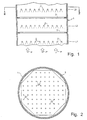
- the open contact reactor shown in the drawing is in the form of an upright, essentially circular-cylindrical tank 1, of which merely a portion is illustrated in Fig. 1.
- a plurality of spray nozzles 2 for spraying finely divided liquid are arranged in the tank 1.
- the spray nozzles 2 are arranged on a plurality of vertically spaced-apart levels L1, L2, L3, the nozzles on each level being uniformly distributed over the cross-section of the tank 1, except in the portion positioned closest to the circumference of the tank 1, in which portion there are no spray nozzles and/or parts of spray nozzles that would imply a uniform distribution over the entire cross-section.
- Each nozzle 2 has a circumferential, conical spray action, by which is here meant that it sprays liquid essentially uniformly distributed over an intended cone or an intended truncated cone.
- the spray action of the nozzles 2 is directed downwards.
- their spray action can also be directed upwards or be directed both upwards and downwards.
- the reactor is used for cleaning process gases containing gaseous pollutants.
- the process gases are conducted essentially vertically through the tank 1 in the direction of the arrows P in order to be contacted with the finely divided liquid.
- the process gases can be conducted through the tank 1 in the direction opposite to the direction of arrows P.
- the liquid consists of water and an absorbent dissolved or suspended therein, which reacts with the gaseous pollutants in the process gases.
- a circumferential gas guiding means 3 which extends along the circumference of the tank 1.
- the gas guiding means 3 are adapted to guide the gas flow closest to the wall of the tank 1 towards the centre axis of the tank essentially perpendicular thereto and, thus, essentially perpendicular to the main gas flow direction P.
- Each gas guiding means 3 has the form of a simple, circumferential horizontal flange, but, for guiding the gas flow towards the centre axis of the container 1, it may also have another form which is suitable for the purpose.
- the gas guiding means 3 can be arcuate in cross-section, but it may also have a more complicated shape and consist of, for instance, a series of bucket-shaped gas guiding elements which are juxtaposed along the circumference of the tank 1.
- the gas guiding means 3 functions to some extent also as liquid guiding means by the gas flow guided towards the centre axis of the tank 1 entraining liquid which is collected on the wall of the tank 1.
- the gas guiding means 3 extends into the tank 1 to a distance from the wall thereof, which distance over the major part of the circumference of the wall at each point corresponds to about 50% of the distance between the nozzle 2 positioned closest to the respective point and the wall.
- Said distance of the gas guiding means 3 may, however, vary between 10 and 90% of said nozzle distance and preferably is between 30 and 65%.
- the arrangement of the gas guiding means 3 has been found to increase the efficiency of the reactor in a favourable manner.
Landscapes
- Engineering & Computer Science (AREA)
- Chemical & Material Sciences (AREA)
- Chemical Kinetics & Catalysis (AREA)
- Oil, Petroleum & Natural Gas (AREA)
- Environmental & Geological Engineering (AREA)
- Analytical Chemistry (AREA)
- General Chemical & Material Sciences (AREA)
- Mechanical Engineering (AREA)
- Health & Medical Sciences (AREA)
- Biomedical Technology (AREA)
- General Engineering & Computer Science (AREA)
- Gas Separation By Absorption (AREA)
- Physical Or Chemical Processes And Apparatus (AREA)
- Treating Waste Gases (AREA)
- Mechanical Control Devices (AREA)
- Steering Control In Accordance With Driving Conditions (AREA)
- Nozzles (AREA)
Abstract
Description
Claims (2)
- An open contact reactor being in the form of a tank (1), in which a plurality of spray nozzles (2) for spraying finely divided liquid are arranged and through which a gas is to be conducted in a main gas flow direction (P) in order to be contacted with the finely divided liquid, the spray nozzles (2) being arranged on different nozzle levels (L1, L2, L3) which are spaced apart in the main gas flow direction, and the nozzles (2) on each level being substantially uniformly distributed over the cross-section of the tank, characterised in that a gas guiding means (3), which extends along the circumference of the tank (1) and is adapted to guide the gas flow closest to the wall of the tank towards the interior of the tank essentially perpendicular to the main gas flow direction (P), is arranged between the levels in at least one pair of juxtaposed nozzle levels (L1-L2, L2-L3), the guiding means (3) extending into the tank (1) to a distance from the wall thereof, which over the major part of the circumference of the wall at each point is 10-90% of the distance between the nozzle (2) positioned closest to the respective point and the wall.
- The reactor as claimed in claim 1, characterised in that said gas guiding means (3) is arranged between the levels in each pair of juxtaposed nozzle levels (L1-L2, L2-L3).
Applications Claiming Priority (3)
| Application Number | Priority Date | Filing Date | Title |
|---|---|---|---|
| SE9700393 | 1997-02-05 | ||
| SE9700393A SE511566C2 (en) | 1997-02-05 | 1997-02-05 | Open contact reactor |
| PCT/SE1998/000185 WO1998033576A1 (en) | 1997-02-05 | 1998-02-03 | Open contact reactor |
Publications (2)
| Publication Number | Publication Date |
|---|---|
| EP0963235A1 EP0963235A1 (en) | 1999-12-15 |
| EP0963235B1 true EP0963235B1 (en) | 2003-12-17 |
Family
ID=20405679
Family Applications (1)
| Application Number | Title | Priority Date | Filing Date |
|---|---|---|---|
| EP98903327A Expired - Lifetime EP0963235B1 (en) | 1997-02-05 | 1998-02-03 | Open contact reactor |
Country Status (14)
| Country | Link |
|---|---|
| EP (1) | EP0963235B1 (en) |
| JP (1) | JP4462455B2 (en) |
| CN (1) | CN1114461C (en) |
| AT (1) | ATE256492T1 (en) |
| AU (1) | AU6009598A (en) |
| CA (1) | CA2279635C (en) |
| DE (1) | DE69820597T2 (en) |
| ES (1) | ES2213268T3 (en) |
| PL (1) | PL189018B1 (en) |
| SE (1) | SE511566C2 (en) |
| SI (1) | SI20062A (en) |
| SK (1) | SK103199A3 (en) |
| TR (1) | TR199901760T2 (en) |
| WO (1) | WO1998033576A1 (en) |
Families Citing this family (9)
| Publication number | Priority date | Publication date | Assignee | Title |
|---|---|---|---|---|
| ES2200599B1 (en) * | 1999-06-03 | 2005-12-16 | Environmetal International Engineering, S.L. | HIGH EFFICIENCY GAS WASH TOWER. |
| US7431270B2 (en) * | 2004-09-17 | 2008-10-07 | Spx Cooling Technologies, Inc. | Heating tower apparatus and method with wind direction adaptation |
| US8128071B2 (en) | 2006-10-03 | 2012-03-06 | Alstom Technology Ltd | Method and apparatus for improved gas/fluid contact |
| CN102688516B (en) * | 2011-11-30 | 2013-12-25 | 河南科技大学 | Deodorizing and dedusting agent for chicken farm and preparation method thereof |
| CN102589316B (en) * | 2012-03-31 | 2014-03-05 | 陆志厅 | Cooling tower |
| CN103341298B (en) * | 2013-07-16 | 2015-06-17 | 宁波市盈信环保设备有限公司 | Flue gas dust removal device |
| CN105617852B (en) * | 2016-03-28 | 2019-04-09 | 上海龙净环保科技工程有限公司 | Desulfurization and dust removal absorption tower with porous flow equalizer |
| CN106139780A (en) * | 2016-08-30 | 2016-11-23 | 无锡市兴盛环保设备有限公司 | A kind of spray system for Tower for purifying waste gas |
| FR3103713B1 (en) | 2019-12-02 | 2022-07-01 | Lab Sa | Installation for the wet purification of exhaust fumes from an engine of a marine vessel |
Family Cites Families (4)
| Publication number | Priority date | Publication date | Assignee | Title |
|---|---|---|---|---|
| DE307579C (en) * | ||||
| US2974936A (en) * | 1957-05-22 | 1961-03-14 | Koppers Co Inc | Absorption apparatus |
| SE9103824L (en) * | 1991-12-23 | 1992-11-30 | Kamyr Ab | SETTING AND CYCLONING DEVICE TO DISABLE Foam Formation |
| KR100264382B1 (en) * | 1992-03-18 | 2000-08-16 | 폰투스 브레뎀 | Apparatus and method for gas cleaning or gas cooling |
-
1997
- 1997-02-05 SE SE9700393A patent/SE511566C2/en not_active IP Right Cessation
-
1998
- 1998-02-03 SI SI9820019A patent/SI20062A/en not_active IP Right Cessation
- 1998-02-03 CN CN98802322A patent/CN1114461C/en not_active Ceased
- 1998-02-03 AU AU60095/98A patent/AU6009598A/en not_active Abandoned
- 1998-02-03 PL PL98335049A patent/PL189018B1/en unknown
- 1998-02-03 TR TR1999/01760T patent/TR199901760T2/en unknown
- 1998-02-03 CA CA002279635A patent/CA2279635C/en not_active Expired - Lifetime
- 1998-02-03 DE DE69820597T patent/DE69820597T2/en not_active Expired - Lifetime
- 1998-02-03 JP JP53234998A patent/JP4462455B2/en not_active Expired - Lifetime
- 1998-02-03 AT AT98903327T patent/ATE256492T1/en not_active IP Right Cessation
- 1998-02-03 SK SK1031-99A patent/SK103199A3/en unknown
- 1998-02-03 EP EP98903327A patent/EP0963235B1/en not_active Expired - Lifetime
- 1998-02-03 ES ES98903327T patent/ES2213268T3/en not_active Expired - Lifetime
- 1998-02-03 WO PCT/SE1998/000185 patent/WO1998033576A1/en not_active Ceased
Also Published As
| Publication number | Publication date |
|---|---|
| CA2279635C (en) | 2005-08-23 |
| ES2213268T3 (en) | 2004-08-16 |
| SI20062A (en) | 2000-04-30 |
| WO1998033576A1 (en) | 1998-08-06 |
| SE9700393L (en) | 1998-08-06 |
| PL189018B1 (en) | 2005-06-30 |
| AU6009598A (en) | 1998-08-25 |
| JP4462455B2 (en) | 2010-05-12 |
| DE69820597T2 (en) | 2004-09-23 |
| TR199901760T2 (en) | 2000-02-21 |
| CA2279635A1 (en) | 1998-08-06 |
| CN1114461C (en) | 2003-07-16 |
| EP0963235A1 (en) | 1999-12-15 |
| CN1246804A (en) | 2000-03-08 |
| PL335049A1 (en) | 2000-03-27 |
| ATE256492T1 (en) | 2004-01-15 |
| DE69820597D1 (en) | 2004-01-29 |
| SK103199A3 (en) | 2000-01-18 |
| JP2001509076A (en) | 2001-07-10 |
| SE511566C2 (en) | 1999-10-18 |
| SE9700393D0 (en) | 1997-02-05 |
Similar Documents
| Publication | Publication Date | Title |
|---|---|---|
| US4202774A (en) | Flow distributor for fluid bed biological reactor | |
| EP0827765B1 (en) | Gas-liquid dispersion devices, gas-liquid contact apparatus and wastewater treatment systems | |
| AU653571B2 (en) | Process for mass transfer between liquid and gaseous media | |
| US5773621A (en) | Gas dispersion pipe for gas-liquid contact, and device for gas-liquid contact making use thereof | |
| CA2431271A1 (en) | Multiple bed downflow reactor | |
| CA2255371A1 (en) | Reactor distribution apparatus and quench zone mixing apparatus | |
| EP0907399A1 (en) | Reactor distribution apparatus and quench zone mixing apparatus | |
| EP0963235A1 (en) | Open contact reactor | |
| KR960040434A (en) | Desulfurization method of waste gas containing sulfurous acid gas | |
| RU96110409A (en) | METHOD FOR DESULFURING AN EXHAUST GAS CONTAINING SULFUR AND GAS | |
| ES2293360T3 (en) | POWER NOZZLE ASSEMBLY. | |
| EP1218077B1 (en) | Vapor-liquid contact apparatus | |
| EP0169620A1 (en) | Apparatus for purifying water, comprising an upflow reactor with an influent distributing system to be connected to a central water supply system | |
| RU99118026A (en) | PLANT FOR PRODUCING POLYJOINING PRODUCTS OF ALKYLENE OXIDES WITH COMBINED REACTOR FOR DISPERSION OF LIQUID IN GAS AND GAS IN LIQUID | |
| US2380826A (en) | Flue gas scrubber | |
| CN208194082U (en) | A kind of desulfurizing tower of improvement | |
| US3143581A (en) | Liquid distributing apparatus | |
| CN214060043U (en) | Back-washing air pipeline of denitrification biological filter | |
| SU683790A1 (en) | Gas-purifying device | |
| SU1755901A1 (en) | Decarbonization apparatus | |
| SU1581352A1 (en) | Stabilizer for foam apparatus | |
| KR910020155A (en) | Faceted FCC Extractor with Reversible Obstacle Skirt with Gas Inlet | |
| MXPA01004052A (en) | Reactor distribution apparatus and quench zone mixing apparatus |
Legal Events
| Date | Code | Title | Description |
|---|---|---|---|
| PUAI | Public reference made under article 153(3) epc to a published international application that has entered the european phase |
Free format text: ORIGINAL CODE: 0009012 |
|
| 17P | Request for examination filed |
Effective date: 19990708 |
|
| AK | Designated contracting states |
Kind code of ref document: A1 Designated state(s): AT BE CH DE DK ES FI FR GB GR IE IT LI LU MC NL PT SE |
|
| GRAH | Despatch of communication of intention to grant a patent |
Free format text: ORIGINAL CODE: EPIDOS IGRA |
|
| GRAS | Grant fee paid |
Free format text: ORIGINAL CODE: EPIDOSNIGR3 |
|
| GRAA | (expected) grant |
Free format text: ORIGINAL CODE: 0009210 |
|
| TPAC | Observations filed by third parties |
Free format text: ORIGINAL CODE: EPIDOSNTIPA |
|
| AK | Designated contracting states |
Kind code of ref document: B1 Designated state(s): AT BE CH DE DK ES FI FR GB GR IE IT LI LU MC NL PT SE |
|
| PG25 | Lapsed in a contracting state [announced via postgrant information from national office to epo] |
Ref country code: NL Free format text: LAPSE BECAUSE OF FAILURE TO SUBMIT A TRANSLATION OF THE DESCRIPTION OR TO PAY THE FEE WITHIN THE PRESCRIBED TIME-LIMIT Effective date: 20031217 Ref country code: LI Free format text: LAPSE BECAUSE OF FAILURE TO SUBMIT A TRANSLATION OF THE DESCRIPTION OR TO PAY THE FEE WITHIN THE PRESCRIBED TIME-LIMIT Effective date: 20031217 Ref country code: FI Free format text: LAPSE BECAUSE OF FAILURE TO SUBMIT A TRANSLATION OF THE DESCRIPTION OR TO PAY THE FEE WITHIN THE PRESCRIBED TIME-LIMIT Effective date: 20031217 Ref country code: CH Free format text: LAPSE BECAUSE OF FAILURE TO SUBMIT A TRANSLATION OF THE DESCRIPTION OR TO PAY THE FEE WITHIN THE PRESCRIBED TIME-LIMIT Effective date: 20031217 Ref country code: BE Free format text: LAPSE BECAUSE OF FAILURE TO SUBMIT A TRANSLATION OF THE DESCRIPTION OR TO PAY THE FEE WITHIN THE PRESCRIBED TIME-LIMIT Effective date: 20031217 Ref country code: AT Free format text: LAPSE BECAUSE OF FAILURE TO SUBMIT A TRANSLATION OF THE DESCRIPTION OR TO PAY THE FEE WITHIN THE PRESCRIBED TIME-LIMIT Effective date: 20031217 |
|
| REG | Reference to a national code |
Ref country code: GB Ref legal event code: FG4D |
|
| REG | Reference to a national code |
Ref country code: CH Ref legal event code: EP |
|
| REG | Reference to a national code |
Ref country code: IE Ref legal event code: FG4D |
|
| REF | Corresponds to: |
Ref document number: 69820597 Country of ref document: DE Date of ref document: 20040129 Kind code of ref document: P |
|
| PG25 | Lapsed in a contracting state [announced via postgrant information from national office to epo] |
Ref country code: LU Free format text: LAPSE BECAUSE OF NON-PAYMENT OF DUE FEES Effective date: 20040203 Ref country code: IE Free format text: LAPSE BECAUSE OF NON-PAYMENT OF DUE FEES Effective date: 20040203 |
|
| PG25 | Lapsed in a contracting state [announced via postgrant information from national office to epo] |
Ref country code: MC Free format text: LAPSE BECAUSE OF NON-PAYMENT OF DUE FEES Effective date: 20040228 |
|
| RAP2 | Party data changed (patent owner data changed or rights of a patent transferred) |
Owner name: ALSTOM SWEDEN AB |
|
| PG25 | Lapsed in a contracting state [announced via postgrant information from national office to epo] |
Ref country code: SE Free format text: LAPSE BECAUSE OF FAILURE TO SUBMIT A TRANSLATION OF THE DESCRIPTION OR TO PAY THE FEE WITHIN THE PRESCRIBED TIME-LIMIT Effective date: 20040317 Ref country code: DK Free format text: LAPSE BECAUSE OF FAILURE TO SUBMIT A TRANSLATION OF THE DESCRIPTION OR TO PAY THE FEE WITHIN THE PRESCRIBED TIME-LIMIT Effective date: 20040317 |
|
| REG | Reference to a national code |
Ref country code: GR Ref legal event code: EP Ref document number: 20040400821 Country of ref document: GR |
|
| NLT2 | Nl: modifications (of names), taken from the european patent patent bulletin |
Owner name: ALSTOM SWEDEN AB |
|
| NLV1 | Nl: lapsed or annulled due to failure to fulfill the requirements of art. 29p and 29m of the patents act | ||
| REG | Reference to a national code |
Ref country code: CH Ref legal event code: PL |
|
| REG | Reference to a national code |
Ref country code: ES Ref legal event code: FG2A Ref document number: 2213268 Country of ref document: ES Kind code of ref document: T3 |
|
| ET | Fr: translation filed | ||
| PLBE | No opposition filed within time limit |
Free format text: ORIGINAL CODE: 0009261 |
|
| STAA | Information on the status of an ep patent application or granted ep patent |
Free format text: STATUS: NO OPPOSITION FILED WITHIN TIME LIMIT |
|
| REG | Reference to a national code |
Ref country code: IE Ref legal event code: MM4A |
|
| 26N | No opposition filed |
Effective date: 20040920 |
|
| PG25 | Lapsed in a contracting state [announced via postgrant information from national office to epo] |
Ref country code: IT Free format text: LAPSE BECAUSE OF NON-PAYMENT OF DUE FEES Effective date: 20050203 |
|
| PG25 | Lapsed in a contracting state [announced via postgrant information from national office to epo] |
Ref country code: PT Free format text: LAPSE BECAUSE OF NON-PAYMENT OF DUE FEES Effective date: 20040517 |
|
| REG | Reference to a national code |
Ref country code: GB Ref legal event code: 732E |
|
| REG | Reference to a national code |
Ref country code: ES Ref legal event code: PC2A |
|
| REG | Reference to a national code |
Ref country code: FR Ref legal event code: TP |
|
| PGRI | Patent reinstated in contracting state [announced from national office to epo] |
Ref country code: IT Effective date: 20091201 |
|
| REG | Reference to a national code |
Ref country code: ES Ref legal event code: PC2A Owner name: ALSTOM TECHNOLOGY LTD. Effective date: 20120809 |
|
| REG | Reference to a national code |
Ref country code: GB Ref legal event code: 732E Free format text: REGISTERED BETWEEN 20120802 AND 20120808 |
|
| REG | Reference to a national code |
Ref country code: FR Ref legal event code: TP Owner name: ALSTOM TECHNOLOGY LTD., CH Effective date: 20121008 |
|
| REG | Reference to a national code |
Ref country code: DE Ref legal event code: R082 Ref document number: 69820597 Country of ref document: DE Representative=s name: ROESLER PATENTANWALTSKANZLEI, DE |
|
| REG | Reference to a national code |
Ref country code: DE Ref legal event code: R082 Ref document number: 69820597 Country of ref document: DE Representative=s name: RUEGER, BARTHELT & ABEL, DE Effective date: 20130508 Ref country code: DE Ref legal event code: R082 Ref document number: 69820597 Country of ref document: DE Representative=s name: ROESLER PATENTANWALTSKANZLEI, DE Effective date: 20130508 Ref country code: DE Ref legal event code: R081 Ref document number: 69820597 Country of ref document: DE Owner name: GENERAL ELECTRIC TECHNOLOGY GMBH, CH Free format text: FORMER OWNER: ALSTOM, LEVALLOIS-PERRET, FR Effective date: 20130508 Ref country code: DE Ref legal event code: R081 Ref document number: 69820597 Country of ref document: DE Owner name: ALSTOM TECHNOLOGY LTD., CH Free format text: FORMER OWNER: ALSTOM, LEVALLOIS-PERRET, FR Effective date: 20130508 |
|
| REG | Reference to a national code |
Ref country code: FR Ref legal event code: PLFP Year of fee payment: 19 |
|
| PGFP | Annual fee paid to national office [announced via postgrant information from national office to epo] |
Ref country code: GR Payment date: 20160216 Year of fee payment: 19 |
|
| REG | Reference to a national code |
Ref country code: DE Ref legal event code: R082 Ref document number: 69820597 Country of ref document: DE Representative=s name: RUEGER, BARTHELT & ABEL, DE |
|
| REG | Reference to a national code |
Ref country code: DE Ref legal event code: R082 Ref document number: 69820597 Country of ref document: DE Representative=s name: RUEGER, BARTHELT & ABEL, DE Ref country code: DE Ref legal event code: R081 Ref document number: 69820597 Country of ref document: DE Owner name: GENERAL ELECTRIC TECHNOLOGY GMBH, CH Free format text: FORMER OWNER: ALSTOM TECHNOLOGY LTD., BADEN, CH |
|
| REG | Reference to a national code |
Ref country code: ES Ref legal event code: PC2A Owner name: GENERAL ELECTRIC TECHNOLOGY GMBH Effective date: 20161115 |
|
| REG | Reference to a national code |
Ref country code: FR Ref legal event code: CD Owner name: ALSTOM TECHNOLOGY LTD, CH Effective date: 20161124 |
|
| REG | Reference to a national code |
Ref country code: FR Ref legal event code: PLFP Year of fee payment: 20 |
|
| PGFP | Annual fee paid to national office [announced via postgrant information from national office to epo] |
Ref country code: FR Payment date: 20170223 Year of fee payment: 20 Ref country code: DE Payment date: 20170227 Year of fee payment: 20 |
|
| PGFP | Annual fee paid to national office [announced via postgrant information from national office to epo] |
Ref country code: GB Payment date: 20170227 Year of fee payment: 20 |
|
| PGFP | Annual fee paid to national office [announced via postgrant information from national office to epo] |
Ref country code: IT Payment date: 20170223 Year of fee payment: 20 Ref country code: ES Payment date: 20170227 Year of fee payment: 20 |
|
| PG25 | Lapsed in a contracting state [announced via postgrant information from national office to epo] |
Ref country code: GR Free format text: LAPSE BECAUSE OF NON-PAYMENT OF DUE FEES Effective date: 20170906 |
|
| REG | Reference to a national code |
Ref country code: DE Ref legal event code: R071 Ref document number: 69820597 Country of ref document: DE |
|
| REG | Reference to a national code |
Ref country code: GB Ref legal event code: PE20 Expiry date: 20180202 |
|
| PG25 | Lapsed in a contracting state [announced via postgrant information from national office to epo] |
Ref country code: GB Free format text: LAPSE BECAUSE OF EXPIRATION OF PROTECTION Effective date: 20180202 |
|
| REG | Reference to a national code |
Ref country code: ES Ref legal event code: FD2A Effective date: 20180525 |
|
| PG25 | Lapsed in a contracting state [announced via postgrant information from national office to epo] |
Ref country code: ES Free format text: LAPSE BECAUSE OF EXPIRATION OF PROTECTION Effective date: 20180204 |