EP0963006B1 - Réseau d'antennes de satellite à commande de phase à faisceaux reconfigurables - Google Patents
Réseau d'antennes de satellite à commande de phase à faisceaux reconfigurables Download PDFInfo
- Publication number
- EP0963006B1 EP0963006B1 EP99110545A EP99110545A EP0963006B1 EP 0963006 B1 EP0963006 B1 EP 0963006B1 EP 99110545 A EP99110545 A EP 99110545A EP 99110545 A EP99110545 A EP 99110545A EP 0963006 B1 EP0963006 B1 EP 0963006B1
- Authority
- EP
- European Patent Office
- Prior art keywords
- ports
- network
- spot
- signals
- array antenna
- Prior art date
- Legal status (The legal status is an assumption and is not a legal conclusion. Google has not performed a legal analysis and makes no representation as to the accuracy of the status listed.)
- Expired - Lifetime
Links
- 230000005540 biological transmission Effects 0.000 claims description 11
- 239000011159 matrix material Substances 0.000 claims description 9
- 238000004891 communication Methods 0.000 description 10
- 230000005855 radiation Effects 0.000 description 6
- 238000010586 diagram Methods 0.000 description 3
- 230000003321 amplification Effects 0.000 description 2
- 238000003491 array Methods 0.000 description 2
- 230000002238 attenuated effect Effects 0.000 description 2
- 238000011161 development Methods 0.000 description 2
- 230000018109 developmental process Effects 0.000 description 2
- 238000003384 imaging method Methods 0.000 description 2
- 238000000034 method Methods 0.000 description 2
- 238000003199 nucleic acid amplification method Methods 0.000 description 2
- 230000010287 polarization Effects 0.000 description 2
- 230000008859 change Effects 0.000 description 1
- 239000002131 composite material Substances 0.000 description 1
- 230000001808 coupling effect Effects 0.000 description 1
- 230000001066 destructive effect Effects 0.000 description 1
- 230000005284 excitation Effects 0.000 description 1
- 238000002044 microwave spectrum Methods 0.000 description 1
- 238000010295 mobile communication Methods 0.000 description 1
- 230000008569 process Effects 0.000 description 1
- 239000007787 solid Substances 0.000 description 1
- 230000007704 transition Effects 0.000 description 1
Images


Classifications
-
- H—ELECTRICITY
- H04—ELECTRIC COMMUNICATION TECHNIQUE
- H04B—TRANSMISSION
- H04B7/00—Radio transmission systems, i.e. using radiation field
- H04B7/14—Relay systems
- H04B7/15—Active relay systems
- H04B7/185—Space-based or airborne stations; Stations for satellite systems
- H04B7/1851—Systems using a satellite or space-based relay
- H04B7/18519—Operations control, administration or maintenance
-
- H—ELECTRICITY
- H01—ELECTRIC ELEMENTS
- H01Q—ANTENNAS, i.e. RADIO AERIALS
- H01Q21/00—Antenna arrays or systems
- H01Q21/06—Arrays of individually energised antenna units similarly polarised and spaced apart
- H01Q21/061—Two dimensional planar arrays
- H01Q21/064—Two dimensional planar arrays using horn or slot aerials
-
- H—ELECTRICITY
- H01—ELECTRIC ELEMENTS
- H01Q—ANTENNAS, i.e. RADIO AERIALS
- H01Q25/00—Antennas or antenna systems providing at least two radiating patterns
- H01Q25/007—Antennas or antenna systems providing at least two radiating patterns using two or more primary active elements in the focal region of a focusing device
- H01Q25/008—Antennas or antenna systems providing at least two radiating patterns using two or more primary active elements in the focal region of a focusing device lens fed multibeam arrays
-
- H—ELECTRICITY
- H01—ELECTRIC ELEMENTS
- H01Q—ANTENNAS, i.e. RADIO AERIALS
- H01Q3/00—Arrangements for changing or varying the orientation or the shape of the directional pattern of the waves radiated from an antenna or antenna system
- H01Q3/24—Arrangements for changing or varying the orientation or the shape of the directional pattern of the waves radiated from an antenna or antenna system varying the orientation by switching energy from one active radiating element to another, e.g. for beam switching
-
- H—ELECTRICITY
- H04—ELECTRIC COMMUNICATION TECHNIQUE
- H04B—TRANSMISSION
- H04B7/00—Radio transmission systems, i.e. using radiation field
- H04B7/14—Relay systems
- H04B7/15—Active relay systems
- H04B7/204—Multiple access
- H04B7/2041—Spot beam multiple access
Definitions
- the present invention relates to a reconfigurable multiple beam phased array antenna comprising:
- the invention relates to phased array antennas and, more particularly, to reconfigurable multiple beam phased array antennas employing Rotman lenses as beamformers.
- antennas are required by communications and radar systems, and depending upon the specific application, antennas can be required for both transmitting and receiving signals.
- Early stages of wireless communications consisted of transmitting and receiving signals at frequencies below 1 MHz which resulted in signal wavelengths greater than 0.3 km.
- a problem with such relatively large wavelengths is that if the size of the antenna is not at least equal to the wavelength, then the antenna is not capable of directional transmission or reception.
- the frequency range of transmitted signals has shifted to the microwave spectrum where signal wavelengths are in the 1.0 cm to 30.0 cm range. Therefore, it is practical for antennas to have sizes much greater than the signal wavelength and achieve highly directional radiation beams.
- phased array antenna includes a collection of radiating elements closely arranged in a predetermined pattern and energized to produce beams in specific directions. When elements are combined in an array, constructive radiation interference results in a main beam of concentrated radiation, while destructive radiation interference outside the main beam reduces stray radiation. To produce desired radiation patterns, each individual radiating element is energized with the proper phase and amplitude relative to the other elements in the array.
- satellite communications systems signals are typically beamed between satellites and fixed coverage region(s) on the Earth.
- satellites With the expanding applications of satellites for many different aspects of communications, market requirements are continuously changing. Accordingly, a satellite must be capable of adapting to changes in the location of the requests for service.
- antennas provided on satellites must be capable of reconfigurable coverages.
- a reconfigurable multiple beam phased array antenna is an ideal solution to the ever changing beam coverage requirements.
- Beam coverage can be in the form of a number of spot beams and regional beams located over specific regions. Spot beams cover discrete and separate areas such as cities. Regional beams cover larger areas such as countries. Regional beams are generated by combining a plurality of spot beams. Spot beams are generated by energizing the radiating elements with selected amplitudes and phases.
- a reconfigurable multiple beam phased array antenna should be capable of reconfiguring the location of the beams, the size of the beams, and the power radiated in each beam.
- a problem with prior art reconfigurable multiple beam phased array antennas is that they deal with uniform sized beams and employ a large number of phase shifters which are used to steer the beams.
- the number of phase shifters is typically the number of elements multiplied by the number of beams.
- the prior art reconfigurable multiple beam phased array antennas have limited bandwidth due to frequency scanning of the beams. The limited bandwidth causes the antenna gain and the co-channel interference (C/I) to degrade.
- US 4,381,509 discloses a three-dimensional space fed wideband scanning microwave antenna.
- the antenna which is cylindrically constrained, can generate highly-focused, multiple, independent beams from line source feeds over a wide scanning range in both azimuth and elevation. It aims at allowing such scanning without using complex time delay units at each radiating element and without bandwidth restrictions in phased arrays caused by path length differences during scan.
- For wideband operation a beam is generated in the general direction of the desired scan sector and then scanned over a limited region of space by means of phase shifters at the radiating elements.
- the present invention provides a reconfigurable beam phased array antenna.
- the array antenna includes a plurality of radiating elements arranged in a planar array and a plurality of variable phase shifters. Each one of the plurality of variable phase shifters is connected to a respective one of the plurality of radiating elements.
- the array antenna further includes a fixed passive beam forming network for forming spot beam signals and a reconfigurable active beamforming network for forming regional beam signals.
- the reconfigurable beam forming network forms regional beam signals from a combination of spot beam signals.
- the fixed beam forming network has stacks of Rotman lenses provided with a first set of ports, a second set of ports and comprising a horizontal and a vertical stack of lenses. Each one of the first set of ports is connected to a respective one of the plurality of radiating elements. The respective one of the plurality of variable phase shifters is interposed therebetween.
- the stacks of Rotman lenses generate frequency invariant spot beam signals which are communicated between the radiating elements and the stacks of Rotman lenses via the first set of ports for transmission and reception of spot beams and regional beams by the plurality of radiating elements.
- the phase shifters are adjusted to: steer the spot beams and the regional beams to desired locations.
- the array antenna also includes a beam divider network having a first set of ports each connected to a respective one of the second set of ports of the stacks of Rotman lenses, the beam divider network further having a second set of paired ports, associated with each port of the first set of ports of the beam divider network.
- the advantages accruing to the present invention are numerous.
- the present invention allows for a common antenna design for various orbital locations/coverage regions and for multiple nonuniform coverage beams thereby reducing the non-recurring design and development cost of future satellites.
- the beam locations are independent of frequency and hence wider bandwidths can be achieved.
- Array antenna 10 is operable for both transmitting and receiving beams simultaneously or intermittently and is intended for use on a satellite (not specifically shown in FIG. 1) .
- Array antenna 10 includes left and right hand circular polarization antenna subsystems 12a and 12b connected to N radiating elements 14(a-n) by respective bandpass filters 16(a-n) and polarizers 18(a-n) along separate individual feed chains 20(a-n).
- Radiating elements 14(a-n) are preferably horns arranged in a hexagonal grid geometry of a planar array by itself or feeding a dual-reflector imaging antenna with confocal paraboloids (not specifically shown). Because subsystems 12a and 12b include the same elements, only antenna subsystem 12a will be described in further detail.
- radiating element 14 bandpass filter 16, and polarizer 18 are preferably combined in an integrated feed assembly 19 as shown.
- Radiating element 14 may be a circular horn such as a Potter horn or a dominant TE 11 mode horn.
- Bandpass filter 16 is an iris filter for rejecting transmitting (T x ) or receiving (R x ) frequencies.
- Polarizer 18 is preferably a septum polarizer.
- Integrated feed assembly 19 further includes a pair of transitions 21(a-b) for receiving left and right hand circular polarization signals from antenna subsystems 12a and 12b, respectively.
- each of feed chains 20(a-n) is connected to a corresponding one of N amplifiers 22(a-n) and N phase shifters 24 (a-n).
- Amplifiers 22(a-n) and phase shifters 24(a-n) act together to energize their associated radiating element 14(a-n) with a signal having a selected amplitude and phase relative to the other elements.
- generated beams can be steered to different orbital locations by adjusting the level of amplification of amplifiers 22 (a-n) and the level of phase shifting of phase shifters 24(a-n).
- the level of amplification is the same for each of amplifiers 22(a-n) and the beams are steered by adjusting phase shifters 24(an).
- the power radiated in the beams can be varied by adjusting amplifiers 22(a-n).
- Amplifiers 22(a-n) are distributed non-redundant amplifiers such as low noise amplifiers on receive mode and solid state power amplifiers on transmit mode.
- Phase shifters 24(a-n) are digitally controlled. In addition to steering the beams to different orbital locations, phase shifters 24(a-n) correct for satellite pointing errors on-orbit and phase variations in feed chains 20(a-n) caused by amplifiers 22(a-n), bandpass filters 18(a-n), and mutual coupling effects among radiating elements 14(a-n).
- Antenna subsystem 12a further includes a low level beam forming network 26.
- Beam forming network 26 includes two dimensional stacks of Rotman lenses 28, a beam divider network 30, and a beam combining network 32. Beam forming network 26 is fully reciprocal and operates to excite radiating elements 14(a-n) to generate spot and regional beams in predetermined directions for both transmitting and receiving.
- a switch matrix 33 is operable with beam forming network 26 to selectively feed energy to or sample energy from the beam forming network.
- beam forming network 26 provides beam signals for discrete multiple excitation to form spot and regional beams, or conversely to separate receive signal energy into discrete corresponding beam signals in accordance with receiving spot and regional beam angles.
- Beam forming network 26 forms beams in two stages.
- the first stage includes Rotman lense stacks 28.
- Rotman lense stacks 28 have N element ports 34(a-n) and L beam ports 36(a-l).
- Each of element ports 34 (a-n) is connected to a respective one of feed chains 20(a-n) to feed individually phased energy discretely to radiating elements 14(a-n) on transmission and receive discretely phased information in accord with the beam directions of array antenna 10 on reception.
- Rotman lense stacks 28 include beam ports 36 (a-l) for receiving and providing L spot beam signals based on the composite coverage of various orbital slots.
- Rotman lense 38 includes input beam ports 40, output element ports 42, and a number of dummy ports (not specifically shown). The dummy ports are terminated in matched loads to minimize internal reflections from lense cavity 44. Rotman lense 38 can be realized in either microstrip or stripline medium.
- Rotman lense stacks 28 include horizontal and vertical stacks of lenses 46 and 48, respectively.
- Each lense of vertical stack of lenses 48 has interconnection ports 50 for connection with corresponding ports of horizontal stack of lenses 46 (not specifically shown in FIG. 4). These interconnections can be achieved by the use of radio frequency (RF) cables.
- One of stack of lenses 46 and 48 includes element ports 34(a-n) for connection with feed chains 20(a-n) (not specifically shown in FIG. 4).
- the other one of stack of lenses 46 and 48 includes beam ports 36(a-l) (not specifically shown in FIG. 4).
- the number of lenses required for Rotman lense stacks 28 is about twice the square root of N, where N is equal to the number of radiating elements, for a square lattice.
- N is equal to the number of radiating elements
- Rotman lense stacks 28 produce beam signals which are invariant of frequency. As a result, transmitted and received beam locations do not change with frequency over the operating frequency band. Rotman lense stacks 28 have this property because they realize the true-time delay (or phase) across radiating elements 14(a-n).
- the second stage of beam forming includes beam divider network 30 and beam combining network 32.
- Beam divider network 30 includes L ports 52(a-l) each connected to a corresponding one of beam ports 36(a-l) of Rotman lense stacks 28. Each of ports 52(a-l) is associated with a pair of L ports 54(a-l) and 56(a-l).
- L spot beam signals from beam ports 36(a-l) enter beam divider network 30 via ports 52(a-l).
- Beam divider network 30 divides each of the L spot beam signals into two signals at ports 54 (a-l) and 56 (a-l).
- the L spot beam signals from ports 54 (a-l) are routed to a corresponding one of L switch ports 58(a-l) of switch matrix 33.
- the other L spot beam signals from ports 56(a-l) are routed to beam combining network 32 through corresponding ports 59 (a-l). From the L spot beam signals, beam combining network 32 generates M regional beam signals.
- beam combining network 32 includes L dividers (1:M) 60(a-l), M variable phase shifter and attenuator pairs 62(a-m) associated with each of the dividers, and M combiners (L:1) 64 (a-m).
- Dividers 60(a-1) divide each of the L spot beam signals from ports 56(a-l) into M ways.
- Each of the divided M signals is routed to phase shifter and attenuator pairs 62 (a-m).
- Phase shifter and attenuator pairs 62(a-m) vary the phase and amplitude of each of the divided M signals.
- Phase shifter and attenuator pairs 62(a-m) are active components and are employed to reconfigure the regional beams.
- beam combining network 32 can be completely passive for fixed regional beams and phase shifter and attenuator pairs 62(a-m) are not required.
- Each of the phase shifted and attenuated divided M signals is then routed to a corresponding one of combiners 64(a-m). For instance, each of the phase shifted and attenuated divided M signals from the first phase shifter and attenuator pair 62a associated with each of dividers 60(a-l) is routed to the first combiner 64a. Similarly, each of the M signals from the second phase shifter and attenuator pair 62b is routed to the second combiner 64b. This process is continued until the M signals from the Mth phase shifter and attenuator pair 62m is routed to the Mth combiner 64m.
- Combiners 64(a-m) combine the L signals from the phase shifter and attenuator pairs 62(a-l) to form M regional beam signals.
- the location and size of the M regional beams are completely reconfigurable by adjusting the phase shifter and attenuator pairs 62(am).
- the M regional beam signals are routed through ports 66(a-m) of beam combining network 32 to ports 68(a-m) of switch matrix 33.
- switch matrix 33 selects desired beams out of the L + M beams.
- the desired beams are selected based on the orbital location of the satellite and on reconfigurability requirements.
- Switch matrix 33 selects desired beams out of the L + M beams for transmission.
- Spot beam signals from ports 58 (a-l) are provided to ports 54 (a-l) of beam divider network 30.
- Regional beam signals from ports 68(a-m) are provided to ports 66(a-m) of beam combiner network 32.
- combiners 64(a-m) When array antenna 10 is in transmission mode, combiners 64(a-m) function as dividers and divide a regional beam signal into L ways. Each of the divided L signals from a combiner is routed to a corresponding one of the M phase shifter and attenuator pairs 62 (a-m). Phase shifter and attenuator pairs 62(a-m) adjust the phase and amplitude of the signals and then route M signals to dividers 60 (a-l). Each of the dividers 60(a-l) functions to combine the provided M signals into one signal. The signal from each of dividers 60 (a-l) is then provided to ports 56(a-l) of beam divider network 30.
- Beam divider network 30 functions now as a combiner and combines the signals from ports 54 (a-l) and 56 (a-l). Ports 36 (a-l) of beam divider network 30 provide the L combined signals to Rotman lense stacks 28. Rotman lense stacks 28 then forms the L spot beam signals for transmission.
- the present invention is applicable to satellite based communication systems. It is particularly of interest to future communications satellites such as personal communication satellites (PCS), direct broadcast satellites (DBS) and mobile communications satellites involving a moderate to large number of multiple spot beams.
- PCS personal communication satellites
- DBS direct broadcast satellites
- mobile communications satellites involving a moderate to large number of multiple spot beams such as personal communication satellites (PCS), direct broadcast satellites (DBS) and mobile communications satellites involving a moderate to large number of multiple spot beams.
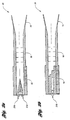
- array antenna 10 employs a parabolic main reflector 70 and a concave parabolic subreflector 72 with both reflectors having a common focal point.
- the planar array of radiating elements 74(a-n) at Ca forms an incident wave on subreflector 72 at Cs.
- Subreflector 72 is located in the near field of radiating elements 74(an) and transforms the approximated plane wave of the radiating elements into a magnified version using the confocal paraboloids.
- the size of the planar array of radiating elements 74 can be reduced by a magnification factor of Mf (Mf > 1) where Mf is the magnification factor of the confocal system of reflectors 70 and 72 and thus, the number of radiating elements can be reduced by Mf 2 as compared to the number of radiating elements of the first embodiment of the present invention.
- the magnification Mf is given by the ratio of the focal lengths of the main and subreflectors 70 and 72 which is equal to ⁇ s / ⁇ n .
- Radiating elements 74 needs to be scanned by Mf multiplied by the scan angle for the beam coverages. Typical values of Mf are in the range of two to three. Thus, the number of radiating elements are therefore reduced by at least a factor of four when compared to the direct radiating array of radiating elements of the first embodiment of the present invention.
Landscapes
- Engineering & Computer Science (AREA)
- Computer Networks & Wireless Communication (AREA)
- Signal Processing (AREA)
- Physics & Mathematics (AREA)
- Astronomy & Astrophysics (AREA)
- Aviation & Aerospace Engineering (AREA)
- General Physics & Mathematics (AREA)
- Variable-Direction Aerials And Aerial Arrays (AREA)
- Aerials With Secondary Devices (AREA)
Claims (8)
- Antenne en réseau à commande de phase et à plusieurs faisceaux reconfigurables, comprenant :- une pluralité d'éléments de rayonnement (14(a-n)) disposés selon un réseau plan ;- une pluralité de circuits de décalage de phase variable (24(a-n)), chaque circuit de la pluralité de circuits de décalage de phase variable (24(a-n)) étant connecté à un élément respectif de la pluralité d'éléments de rayonnement (14(a-n)) ; et- un réseau de formation de faisceau (26) pour former des signaux de faisceau ponctuel, le réseau de formation de faisceau (26) possédant des piles horizontales et verticales (28) de lentilles de Rotman (38), lesdites deux piles étant connectées en série, munies d'un premier ensemble de connecteurs (34(a-n)) et d'un second ensemble de connecteurs (36(a-I)), chaque connecteur du premier ensemble de connecteurs (34(a-n)) étant connecté à un élément respectif de la pluralité d'éléments de rayonnement (14(a-n)) avec interposition du circuit respectif de la pluralité de circuits de décalage de phase variable (24(a-n)), dans lequel les piles (28) de lentilles de Rotman (38) génèrent des signaux de faisceau ponctuel à fréquence fixe qui sont transmis entre les éléments de rayonnement (14(a-n)) et les piles (28) de lentilles de Rotman (38) par l'intermédiaire du premier ensemble de connecteurs (34(a-n)) pour l'émission et la réception des faisceaux ponctuels par la pluralité d'éléments de rayonnement (14(a-n)) ;dans laquelle les circuits de décalage de phase (24(a-n)) sont réglables pour diriger les faisceaux ponctuels vers des positions désirées ;
caractérisée en ce que :- le réseau de formation de faisceau (26) forme, de même, des signaux de faisceau local à partir d'une combinaison de signaux de faisceau ponctuel ; et- le réseau de formation de faisceau (26) comprend, de plus, un réseau de diviseur de faisceau (30) possédant un premier ensemble de connecteurs (52(a-I)) connectés chacun à un connecteur respectif du second ensemble de connecteurs (36(a-I)) des piles (28) de lentilles de Rotman (38), le réseau de diviseur de faisceau (30) possédant, de plus, un second ensemble de connecteurs appariés (54(a-I)), (56(a-I)) associés à chaque connecteur du premier ensemble de connecteurs (36(a-I)) du réseau de diviseur de faisceau (30). - Antenne en réseau selon la revendication 1, caractérisée par une matrice de commutation (33) pouvant fonctionner avec le réseau de formation de faisceau (26).
- Antenne en réseau selon la revendication 1 ou 2, caractérisée en ce que le réseau de formation de faisceau (26) comprend, de plus :un réseau de combinaison de faisceau (32) possédant un premier ensemble de connecteurs (59(a-I)) connectés chacun à un connecteur d'une paire respective du second ensemble de connecteurs appariés (56(a-I)) du réseau de diviseur de faisceau (30), le réseau de combinaison de faisceau (32) possédant, de plus, un second ensemble de connecteurs (66(a-m)).
- Antenne en réseau selon les revendications 2 et 3, caractérisée en ce que le réseau de combinaison de faisceau (32) forme des signaux de faisceau ponctuel à partir des signaux de faisceau local fournis au réseau de combinaison de faisceau (32) à partir de la matrice de commutation (33) lors de la transmission des faisceaux ponctuels et des faisceaux locaux par la pluralité d'éléments de rayonnement (14(a-n)).
- Antenne en réseau selon la revendication 3 ou 4, caractérisée en ce que le réseau de combinaison de faisceau (32) fournit chacun des signaux de faisceau ponctuel à un connecteur correspondant de chaque paire du second ensemble de connecteurs appariés (56(a-I)) du réseau de diviseur de faisceau (30).
- Antenne en réseau selon les revendications 2 et 5, caractérisée en ce que l'autre connecteur de chaque paire du second ensemble de connecteurs appariés (54(a-I)) reçoit un signal de faisceau ponctuel à partir de la matrice de commutation (33).
- Antenne en réseau selon l'une quelconque des revendications 1 à 6, caractérisée en ce que le réseau de diviseur de faisceau (30) combine les signaux de faisceau ponctuel à partir de chaque connecteur du second ensemble de connecteurs appariés (54(a-I)), (56(a-I)) et fournit les signaux combinés de faisceau ponctuel à chacun d'un connecteur correspondant du second ensemble de connecteurs (36(a-I)) des piles (28) de lentilles de Rotman (38).
- Antenne en réseau selon la revendication 3, caractérisée en ce que le réseau de combinaison de faisceau (32) comprend des réseaux de diviseur (60(a-I)), des paires de décalage et d'atténuateur de phase variable (62(a-m)) et des réseaux de combinaison (64(a-m)) pour former des signaux de faisceau ponctuel à partir de signaux de faisceau local lors d'une réception et pour former des signaux de faisceau local à partir des signaux de faisceau ponctuel lors d'une émission.
Applications Claiming Priority (2)
| Application Number | Priority Date | Filing Date | Title |
|---|---|---|---|
| US09/092,511 US5936588A (en) | 1998-06-05 | 1998-06-05 | Reconfigurable multiple beam satellite phased array antenna |
| US92511 | 1998-06-05 |
Publications (3)
| Publication Number | Publication Date |
|---|---|
| EP0963006A2 EP0963006A2 (fr) | 1999-12-08 |
| EP0963006A3 EP0963006A3 (fr) | 2001-04-04 |
| EP0963006B1 true EP0963006B1 (fr) | 2006-03-22 |
Family
ID=22233579
Family Applications (1)
| Application Number | Title | Priority Date | Filing Date |
|---|---|---|---|
| EP99110545A Expired - Lifetime EP0963006B1 (fr) | 1998-06-05 | 1999-06-01 | Réseau d'antennes de satellite à commande de phase à faisceaux reconfigurables |
Country Status (3)
| Country | Link |
|---|---|
| US (1) | US5936588A (fr) |
| EP (1) | EP0963006B1 (fr) |
| DE (1) | DE69930441T2 (fr) |
Cited By (2)
| Publication number | Priority date | Publication date | Assignee | Title |
|---|---|---|---|---|
| US9543662B2 (en) | 2014-03-06 | 2017-01-10 | Raytheon Company | Electronic Rotman lens |
| US10103446B2 (en) | 2015-01-08 | 2018-10-16 | Vorbeck Materials Corp. | Graphene-based rotman lens |
Families Citing this family (64)
| Publication number | Priority date | Publication date | Assignee | Title |
|---|---|---|---|---|
| US6125261A (en) | 1997-06-02 | 2000-09-26 | Hughes Electronics Corporation | Method and system for communicating high rate data in a satellite-based communications network |
| US6304225B1 (en) * | 1998-08-21 | 2001-10-16 | Raytheon Company | Lens system for antenna system |
| US6160519A (en) * | 1998-08-21 | 2000-12-12 | Raytheon Company | Two-dimensionally steered antenna system |
| US6130653A (en) * | 1998-09-29 | 2000-10-10 | Raytheon Company | Compact stripline Rotman lens |
| US6301465B1 (en) * | 1998-10-12 | 2001-10-09 | Trw Inc. | Adaptive transceiver architecture for real time allocation of communications resources in a satellite based telecommunication system |
| US6295035B1 (en) * | 1998-11-30 | 2001-09-25 | Raytheon Company | Circular direction finding antenna |
| US6438354B2 (en) * | 1998-12-23 | 2002-08-20 | Hughes Electronics Corporation | Reconfigurable satellite and antenna coverage communications backup capabilities |
| US7327698B1 (en) | 1999-06-03 | 2008-02-05 | The Directv Group, Inc. | Method and system for providing satellite communications using on-orbit payload configuration and reconfiguration |
| US6295026B1 (en) * | 1999-11-19 | 2001-09-25 | Trw Inc. | Enhanced direct radiating array |
| US6275184B1 (en) | 1999-11-30 | 2001-08-14 | Raytheon Company | Multi-level system and method for steering an antenna |
| FR2811480B1 (fr) | 2000-07-06 | 2006-09-08 | Cit Alcatel | Antenne de telecommunication destinee a couvrir une large zone terrestre |
| US7013137B2 (en) * | 2000-07-14 | 2006-03-14 | Comsat Corporation | Smaller aperture antenna for multiple spot beam satellites |
| DE10034911A1 (de) * | 2000-07-18 | 2002-02-07 | Kathrein Werke Kg | Antenne für Mehrfrequenzbetrieb |
| DE10057564A1 (de) * | 2000-11-21 | 2002-05-23 | Volkswagen Ag | Ansteuernetzwerk für eine Antennenanordnung eines Radarsensors, Radarantenne und Radarsensor |
| US6456251B1 (en) | 2001-05-17 | 2002-09-24 | The Boeing Company | Reconfigurable antenna system |
| US6807343B2 (en) * | 2001-05-29 | 2004-10-19 | The United States Of America As Represented By The Secretary Of The Navy | Reconfigurable optical beamformer for simplified time steered arrays |
| US6570528B1 (en) | 2001-11-09 | 2003-05-27 | The Boeing Company | Antenna system for multiple orbits and multiple areas |
| US6906665B1 (en) * | 2002-11-15 | 2005-06-14 | Lockheed Martin Corporation | Cluster beam-forming system and method |
| US6828932B1 (en) | 2003-01-17 | 2004-12-07 | Itt Manufacutring Enterprises, Inc. | System for receiving multiple independent RF signals having different polarizations and scan angles |
| US6982676B2 (en) * | 2003-04-18 | 2006-01-03 | Hrl Laboratories, Llc | Plano-convex rotman lenses, an ultra wideband array employing a hybrid long slot aperture and a quasi-optic beam former |
| FR2860107B1 (fr) * | 2003-09-23 | 2006-01-13 | Cit Alcatel | Antenne reseau reflecteur reconfigurable a faibles pertes |
| US6940452B2 (en) * | 2003-09-29 | 2005-09-06 | Northrop Grumman Corporation | Reducing co-channel interference in satellite communications systems by antenna re-pointing |
| US7511666B2 (en) | 2005-04-29 | 2009-03-31 | Lockheed Martin Corporation | Shared phased array cluster beamformer |
| US7710340B2 (en) * | 2006-01-13 | 2010-05-04 | Lockheed Martin Corporation | Reconfigurable payload using non-focused reflector antenna for HIEO and GEO satellites |
| US8354956B2 (en) * | 2006-01-13 | 2013-01-15 | Lockheed Martin Corporation | Space segment payload architecture for mobile satellite services (MSS) systems |
| US7672640B2 (en) * | 2006-04-05 | 2010-03-02 | Emscan Corporation | Multichannel absorberless near field measurement system |
| TWI422838B (zh) * | 2006-04-05 | 2014-01-11 | Emscan Corp | 多頻道無吸收器之近場測量系統 |
| US9857475B2 (en) * | 2008-09-09 | 2018-01-02 | Geooptics, Inc. | Cellular interferometer for continuous earth remote observation (CICERO) |
| TW201126815A (en) * | 2009-11-06 | 2011-08-01 | Viasat Inc | Electromechanical polarization switch |
| KR20120065652A (ko) * | 2010-12-13 | 2012-06-21 | 한국전자통신연구원 | 레이더 센서용 rf 송수신기 |
| US9041603B2 (en) * | 2011-12-21 | 2015-05-26 | Raytheon Company | Method and apparatus for doubling the capacity of a lens-based switched beam antenna system |
| JP5966419B2 (ja) * | 2012-02-20 | 2016-08-10 | 日立化成株式会社 | アンテナ走査装置およびそれを用いた無線装置 |
| US9244163B2 (en) * | 2012-05-17 | 2016-01-26 | Farrokh Mohamadi | Integrated ultra wideband, wafer scale, RHCP-LHCP arrays |
| FR3005211B1 (fr) | 2013-04-26 | 2015-05-29 | Thales Sa | Dispositif d'alimentation distribuee pour formation de faisceau d'antenne |
| US9373896B2 (en) | 2013-09-05 | 2016-06-21 | Viasat, Inc | True time delay compensation in wideband phased array fed reflector antenna systems |
| US11855680B2 (en) * | 2013-09-06 | 2023-12-26 | John Howard | Random, sequential, or simultaneous multi-beam circular antenna array and beam forming networks with up to 360° coverage |
| WO2015142723A1 (fr) | 2014-03-17 | 2015-09-24 | Ubiquiti Networks, Inc. | Antennes réseau possédant une pluralité de faisceaux directionnels |
| KR20160148701A (ko) * | 2014-05-02 | 2016-12-26 | 파커비전, 인크. | 통신 시스템용 안테나 어레이 |
| US10164332B2 (en) | 2014-10-14 | 2018-12-25 | Ubiquiti Networks, Inc. | Multi-sector antennas |
| US10732249B2 (en) | 2014-11-12 | 2020-08-04 | Ether Capital Corporation | Reactive near-field antenna measurement |
| US10284268B2 (en) | 2015-02-23 | 2019-05-07 | Ubiquiti Networks, Inc. | Radio apparatuses for long-range communication of radio-frequency information |
| FR3034262B1 (fr) | 2015-03-23 | 2018-06-01 | Thales | Matrice de butler compacte, formateur de faisceaux bidimensionnel planaire et antenne plane comportant une telle matrice de butler |
| FR3038457B1 (fr) | 2015-07-03 | 2017-07-28 | Thales Sa | Formateur de faisceaux quasi-optique a lentille et antenne plane comportant un tel formateur de faisceaux |
| US10553943B2 (en) | 2015-09-22 | 2020-02-04 | Qualcomm Incorporated | Low-cost satellite user terminal antenna |
| CN107040294B (zh) | 2015-10-09 | 2020-10-16 | 优倍快公司 | 同步多无线电天线系统和方法 |
| CN108352619B (zh) * | 2015-10-26 | 2020-12-08 | 华为技术有限公司 | 一种反射面天线及天线对准方法 |
| FR3044832B1 (fr) | 2015-12-04 | 2018-01-05 | Thales | Architecture d'antenne active a formation de faisceaux hybride reconfigurable |
| US10199742B2 (en) | 2016-04-19 | 2019-02-05 | Raytheon Company | Passive frequency multiplexer |
| US10305195B2 (en) | 2016-07-11 | 2019-05-28 | Space Systems/Loral, Llc | Imaging array fed reflector |
| US9923712B2 (en) | 2016-08-01 | 2018-03-20 | Movandi Corporation | Wireless receiver with axial ratio and cross-polarization calibration |
| US10291296B2 (en) | 2016-09-02 | 2019-05-14 | Movandi Corporation | Transceiver for multi-beam and relay with 5G application |
| US10199717B2 (en) | 2016-11-18 | 2019-02-05 | Movandi Corporation | Phased array antenna panel having reduced passive loss of received signals |
| FR3062524B1 (fr) * | 2017-02-01 | 2021-04-09 | Thales Sa | Antenne elementaire a dispositif rayonnant planaire |
| WO2018222556A1 (fr) | 2017-06-02 | 2018-12-06 | Flir Systems, Inc. | Systèmes et procédés de télémétrie avec transducteurs multicanaux décalés |
| WO2019000179A1 (fr) | 2017-06-26 | 2019-01-03 | 华为技术有限公司 | Appareil d'alimentation électrique |
| US10484078B2 (en) | 2017-07-11 | 2019-11-19 | Movandi Corporation | Reconfigurable and modular active repeater device |
| US10236961B2 (en) | 2017-07-14 | 2019-03-19 | Facebook, Inc. | Processsing of beamforming signals of a passive time-delay structure |
| FR3069713B1 (fr) * | 2017-07-27 | 2019-08-02 | Thales | Antenne integrant des lentilles a retard a l'interieur d'un repartiteur a base de diviseurs a guide d'ondes a plaques paralleles |
| US10887024B2 (en) * | 2018-10-03 | 2021-01-05 | Raytheon Company | Optical beamforming photonic integrated circuit (PIC) |
| US10574337B1 (en) | 2019-02-11 | 2020-02-25 | Gogo Llc | Multi-constellation satellite terminal |
| FR3098024B1 (fr) | 2019-06-27 | 2022-06-03 | Thales Sa | Formateur analogique multifaisceaux bidimensionnel de complexité réduite pour antennes réseaux actives reconfigurables |
| US11444377B2 (en) * | 2019-10-03 | 2022-09-13 | Aptiv Technologies Limited | Radiation pattern reconfigurable antenna |
| GB2612820A (en) * | 2021-11-12 | 2023-05-17 | International Electric Company Ltd | A radio frequency circuit with passive phase gain |
| CN115296044B (zh) * | 2022-07-06 | 2024-04-30 | 中国电子科技集团公司第三十八研究所 | 一种多波束相控阵天线系统 |
Family Cites Families (16)
| Publication number | Priority date | Publication date | Assignee | Title |
|---|---|---|---|---|
| US3979754A (en) * | 1975-04-11 | 1976-09-07 | Raytheon Company | Radio frequency array antenna employing stacked parallel plate lenses |
| US4087822A (en) * | 1976-08-26 | 1978-05-02 | Raytheon Company | Radio frequency antenna having microstrip feed network and flared radiating aperture |
| US4381509A (en) * | 1981-02-23 | 1983-04-26 | The United States Of America As Represented By The Secretary Of The Air Force | Cylindrical microwave lens antenna for wideband scanning applications |
| US4408205A (en) * | 1981-06-25 | 1983-10-04 | International Telephone And Telegraph Corporation | Multiple beam antenna feed arrangement for generating an arbitrary number of independent steerable nulls |
| US4799065A (en) * | 1983-03-17 | 1989-01-17 | Hughes Aircraft Company | Reconfigurable beam antenna |
| US4845507A (en) * | 1987-08-07 | 1989-07-04 | Raytheon Company | Modular multibeam radio frequency array antenna system |
| FR2628896B1 (fr) * | 1988-03-18 | 1990-11-16 | Alcatel Espace | Antenne a reconfiguration electronique en emission |
| FR2628895B1 (fr) * | 1988-03-18 | 1990-11-16 | Alcatel Espace | Antenne a balayage electronique |
| US4937584A (en) * | 1988-12-22 | 1990-06-26 | United States Of America As Represented By The Secretary Of The Navy | Adaptive phase-shifter nulling techniques for large-aperture phases arrays |
| FR2652452B1 (fr) * | 1989-09-26 | 1992-03-20 | Europ Agence Spatiale | Dispositif d'alimentation d'une antenne a faisceaux multiples. |
| US5003315A (en) * | 1990-09-27 | 1991-03-26 | The United States Of America As Represented By The Secretary Of The Navy | Progressive phase-Rotman-Turner lens feed transmission line network |
| US5289193A (en) * | 1990-11-29 | 1994-02-22 | Alcatel Espace | Reconfigurable transmission antenna |
| US5329248A (en) * | 1991-12-11 | 1994-07-12 | Loral Aerospace Corp. | Power divider/combiner having wide-angle microwave lenses |
| FR2685551B1 (fr) * | 1991-12-23 | 1994-01-28 | Alcatel Espace | Antenne active "offset" a double reflecteurs. |
| US5495258A (en) * | 1994-09-01 | 1996-02-27 | Nicholas L. Muhlhauser | Multiple beam antenna system for simultaneously receiving multiple satellite signals |
| EP0786826A3 (fr) * | 1996-01-29 | 1999-06-02 | Hughes Electronics Corporation | Dispositif de communication à dispersion d'intermodulation |
-
1998
- 1998-06-05 US US09/092,511 patent/US5936588A/en not_active Expired - Lifetime
-
1999
- 1999-06-01 DE DE69930441T patent/DE69930441T2/de not_active Expired - Lifetime
- 1999-06-01 EP EP99110545A patent/EP0963006B1/fr not_active Expired - Lifetime
Cited By (2)
| Publication number | Priority date | Publication date | Assignee | Title |
|---|---|---|---|---|
| US9543662B2 (en) | 2014-03-06 | 2017-01-10 | Raytheon Company | Electronic Rotman lens |
| US10103446B2 (en) | 2015-01-08 | 2018-10-16 | Vorbeck Materials Corp. | Graphene-based rotman lens |
Also Published As
| Publication number | Publication date |
|---|---|
| US5936588A (en) | 1999-08-10 |
| EP0963006A3 (fr) | 2001-04-04 |
| DE69930441D1 (de) | 2006-05-11 |
| EP0963006A2 (fr) | 1999-12-08 |
| DE69930441T2 (de) | 2006-11-30 |
Similar Documents
| Publication | Publication Date | Title |
|---|---|---|
| EP0963006B1 (fr) | Réseau d'antennes de satellite à commande de phase à faisceaux reconfigurables | |
| EP3259805B1 (fr) | Groupement à déphasage reconfigurable alimenté dans l'espace à bas coût pour applications aérospatiales et aéronautiques | |
| US6169513B1 (en) | Thinned multiple beam phased array antenna | |
| US6456252B1 (en) | Phase-only reconfigurable multi-feed reflector antenna for shaped beams | |
| US5936592A (en) | Reconfigurable multiple beam satellite reflector antenna with an array feed | |
| US5115248A (en) | Multibeam antenna feed device | |
| US4973972A (en) | Stripline feed for a microstrip array of patch elements with teardrop shaped probes | |
| JP2585399B2 (ja) | デュアルモード位相アレイアンテナシステム | |
| RU2162260C2 (ru) | Антенная система | |
| US6366256B1 (en) | Multi-beam reflector antenna system with a simple beamforming network | |
| US5128687A (en) | Shared aperture antenna for independently steered, multiple simultaneous beams | |
| US6246364B1 (en) | Light-weight modular low-level reconfigurable beamformer for array antennas | |
| JP2728282B2 (ja) | アクティブ・フェーズ・アレイ・アンテナ用の等パワー増幅器システムおよびその配置方法 | |
| US4965588A (en) | Electronically scanned antenna | |
| US5909191A (en) | Multiple beam antenna and beamforming network | |
| WO2002025775A1 (fr) | Antenne adaptative multi-faisceau a bande ultra-large | |
| US5940048A (en) | Conical omni-directional coverage multibeam antenna | |
| EP1972030B1 (fr) | Charge reconfigurable utilisant une antenne de reflecteur non ciblee pour des satellites hieo et geo | |
| JPH04319804A (ja) | 1以上の幅及び/又は方向を変更可能なビームを有するアンテナの放射パターンの電子制御装置 | |
| US5038147A (en) | Electronically scanned antenna | |
| JPH01502872A (ja) | 複数レベルビーム形成回路網 | |
| JP3284837B2 (ja) | 分配合成装置とアンテナ装置 | |
| CN210111047U (zh) | 用于天线的馈电网络及天线 | |
| US6504516B1 (en) | Hexagonal array antenna for limited scan spatial applications | |
| JP2022539676A (ja) | イメージング反射器アンテナシステム |
Legal Events
| Date | Code | Title | Description |
|---|---|---|---|
| PUAI | Public reference made under article 153(3) epc to a published international application that has entered the european phase |
Free format text: ORIGINAL CODE: 0009012 |
|
| AK | Designated contracting states |
Kind code of ref document: A2 Designated state(s): DE FR GB |
|
| AX | Request for extension of the european patent |
Free format text: AL;LT;LV;MK;RO;SI |
|
| PUAL | Search report despatched |
Free format text: ORIGINAL CODE: 0009013 |
|
| AK | Designated contracting states |
Kind code of ref document: A3 Designated state(s): AT BE CH CY DE DK ES FI FR GB GR IE IT LI LU MC NL PT SE |
|
| AX | Request for extension of the european patent |
Free format text: AL;LT;LV;MK;RO;SI |
|
| 17P | Request for examination filed |
Effective date: 20010921 |
|
| AKX | Designation fees paid |
Free format text: DE FR GB |
|
| 17Q | First examination report despatched |
Effective date: 20050124 |
|
| GRAP | Despatch of communication of intention to grant a patent |
Free format text: ORIGINAL CODE: EPIDOSNIGR1 |
|
| GRAS | Grant fee paid |
Free format text: ORIGINAL CODE: EPIDOSNIGR3 |
|
| GRAA | (expected) grant |
Free format text: ORIGINAL CODE: 0009210 |
|
| AK | Designated contracting states |
Kind code of ref document: B1 Designated state(s): DE FR GB |
|
| REG | Reference to a national code |
Ref country code: GB Ref legal event code: FG4D |
|
| REF | Corresponds to: |
Ref document number: 69930441 Country of ref document: DE Date of ref document: 20060511 Kind code of ref document: P |
|
| ET | Fr: translation filed | ||
| PLBE | No opposition filed within time limit |
Free format text: ORIGINAL CODE: 0009261 |
|
| STAA | Information on the status of an ep patent application or granted ep patent |
Free format text: STATUS: NO OPPOSITION FILED WITHIN TIME LIMIT |
|
| 26N | No opposition filed |
Effective date: 20061227 |
|
| REG | Reference to a national code |
Ref country code: FR Ref legal event code: PLFP Year of fee payment: 18 |
|
| REG | Reference to a national code |
Ref country code: FR Ref legal event code: PLFP Year of fee payment: 19 |
|
| REG | Reference to a national code |
Ref country code: FR Ref legal event code: PLFP Year of fee payment: 20 |
|
| PGFP | Annual fee paid to national office [announced via postgrant information from national office to epo] |
Ref country code: FR Payment date: 20180626 Year of fee payment: 20 |
|
| PGFP | Annual fee paid to national office [announced via postgrant information from national office to epo] |
Ref country code: GB Payment date: 20180627 Year of fee payment: 20 Ref country code: DE Payment date: 20180627 Year of fee payment: 20 |
|
| REG | Reference to a national code |
Ref country code: DE Ref legal event code: R071 Ref document number: 69930441 Country of ref document: DE |
|
| REG | Reference to a national code |
Ref country code: GB Ref legal event code: PE20 Expiry date: 20190531 |
|
| PG25 | Lapsed in a contracting state [announced via postgrant information from national office to epo] |
Ref country code: GB Free format text: LAPSE BECAUSE OF EXPIRATION OF PROTECTION Effective date: 20190531 |