EP0962637B1 - Engine power control for a motor vehicle equipped with a power control element - Google Patents
Engine power control for a motor vehicle equipped with a power control element Download PDFInfo
- Publication number
- EP0962637B1 EP0962637B1 EP99108408A EP99108408A EP0962637B1 EP 0962637 B1 EP0962637 B1 EP 0962637B1 EP 99108408 A EP99108408 A EP 99108408A EP 99108408 A EP99108408 A EP 99108408A EP 0962637 B1 EP0962637 B1 EP 0962637B1
- Authority
- EP
- European Patent Office
- Prior art keywords
- power control
- power
- engine
- acceleration
- driver
- Prior art date
- Legal status (The legal status is an assumption and is not a legal conclusion. Google has not performed a legal analysis and makes no representation as to the accuracy of the status listed.)
- Expired - Lifetime
Links
- 230000001133 acceleration Effects 0.000 claims description 20
- 230000000994 depressogenic effect Effects 0.000 description 2
- 238000002485 combustion reaction Methods 0.000 description 1
- 230000000052 comparative effect Effects 0.000 description 1
- 230000003111 delayed effect Effects 0.000 description 1
- 230000001419 dependent effect Effects 0.000 description 1
- 230000000694 effects Effects 0.000 description 1
- 238000002347 injection Methods 0.000 description 1
- 239000007924 injection Substances 0.000 description 1
- 210000000056 organ Anatomy 0.000 description 1
- 230000008092 positive effect Effects 0.000 description 1
- 230000001105 regulatory effect Effects 0.000 description 1
- 239000000243 solution Substances 0.000 description 1
Images
Classifications
-
- F—MECHANICAL ENGINEERING; LIGHTING; HEATING; WEAPONS; BLASTING
- F02—COMBUSTION ENGINES; HOT-GAS OR COMBUSTION-PRODUCT ENGINE PLANTS
- F02D—CONTROLLING COMBUSTION ENGINES
- F02D11/00—Arrangements for, or adaptations to, non-automatic engine control initiation means, e.g. operator initiated
- F02D11/06—Arrangements for, or adaptations to, non-automatic engine control initiation means, e.g. operator initiated characterised by non-mechanical control linkages, e.g. fluid control linkages or by control linkages with power drive or assistance
- F02D11/10—Arrangements for, or adaptations to, non-automatic engine control initiation means, e.g. operator initiated characterised by non-mechanical control linkages, e.g. fluid control linkages or by control linkages with power drive or assistance of the electric type
- F02D11/105—Arrangements for, or adaptations to, non-automatic engine control initiation means, e.g. operator initiated characterised by non-mechanical control linkages, e.g. fluid control linkages or by control linkages with power drive or assistance of the electric type characterised by the function converting demand to actuation, e.g. a map indicating relations between an accelerator pedal position and throttle valve opening or target engine torque
-
- F—MECHANICAL ENGINEERING; LIGHTING; HEATING; WEAPONS; BLASTING
- F02—COMBUSTION ENGINES; HOT-GAS OR COMBUSTION-PRODUCT ENGINE PLANTS
- F02D—CONTROLLING COMBUSTION ENGINES
- F02D41/00—Electrical control of supply of combustible mixture or its constituents
- F02D41/22—Safety or indicating devices for abnormal conditions
- F02D41/221—Safety or indicating devices for abnormal conditions relating to the failure of actuators or electrically driven elements
-
- F—MECHANICAL ENGINEERING; LIGHTING; HEATING; WEAPONS; BLASTING
- F02—COMBUSTION ENGINES; HOT-GAS OR COMBUSTION-PRODUCT ENGINE PLANTS
- F02D—CONTROLLING COMBUSTION ENGINES
- F02D2250/00—Engine control related to specific problems or objectives
- F02D2250/18—Control of the engine output torque
- F02D2250/26—Control of the engine output torque by applying a torque limit
-
- Y—GENERAL TAGGING OF NEW TECHNOLOGICAL DEVELOPMENTS; GENERAL TAGGING OF CROSS-SECTIONAL TECHNOLOGIES SPANNING OVER SEVERAL SECTIONS OF THE IPC; TECHNICAL SUBJECTS COVERED BY FORMER USPC CROSS-REFERENCE ART COLLECTIONS [XRACs] AND DIGESTS
- Y02—TECHNOLOGIES OR APPLICATIONS FOR MITIGATION OR ADAPTATION AGAINST CLIMATE CHANGE
- Y02T—CLIMATE CHANGE MITIGATION TECHNOLOGIES RELATED TO TRANSPORTATION
- Y02T10/00—Road transport of goods or passengers
- Y02T10/10—Internal combustion engine [ICE] based vehicles
- Y02T10/40—Engine management systems
Definitions
- the invention relates to an engine power control for motor vehicles with a performance control body according to the preamble of the claim 1.
- a performance control body e.g. B. a throttle valve Cable an electronic control unit, preferably the electric motor Power control organ.
- the system is therefore able to for example the throttle valve in Otto engines or the Injection in diesel engines, depending on various operating parameters to control z.
- a pedal travel sensor usually detects this the accelerator pedal position and performs a corresponding electrical Signal to the electronic control unit.
- the control unit calculates from this the control signal for, for example, the throttle valve actuator and also takes into account the input signals of other systems (e.g. from Traction control and / or engine control).
- a constant Checking all components by the control unit ensures the flawless System function safe.
- the sensors and the computers of the Control units are preferably designed to be duplicated by comparison a reliable plausibility check for the respective signals enable.
- the technical background is, for example, the newspaper article Electronics concept for the BMW 12-cylinder engine ", automotive industry No. 1/88, page 19 ff.
- the engine power is on limits a maximum permissible engine torque value and the vehicle dynamics limited. If the driver's performance requirements increase during of emergency driving, e.g. B. when accelerating again after releasing the Accelerator pedal during a shift, the engine torque is controlled via a defined ramp step by step up to the maximum permissible engine torque regardless of the resulting vehicle speed curve or the acceleration released. The resulting one Acceleration curve due to the fixed engine torque ramp is dependent on vehicle parameters, engine parameters and gear. The celebration predetermined ramp is used for a certain operating point, in particular designed for the worst case.
- the invention is based on the idea that the driver feels the vehicle dynamics directly with the acceleration behavior of the Vehicle is connected. Therefore, according to the invention, emergency driving is started based on the actual vehicle acceleration.
- the invention sees a regulation of the power control body in such a way that with increased An immediate performance requirement without (noticeable) delay Acceleration is initiated and that if the increased power requirement a predetermined preferably dynamic effective acceleration curve until the maximum permissible Motor torque results.
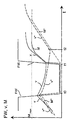
- the predetermined acceleration curve in the form of a speed curve v and the engine torque curve M resulting from the regulation of the power control element in accordance with the predetermined speed curve v are shown as a function of the power requirement FW during an emergency drive.
- the driver Before time t0, the driver has a maximum power requirement FW, for example due to the accelerator pedal being fully depressed.
- the accelerator pedal e.g. B. completely released due to a planned gear change, whereby the power requirement FW drops to the value 0, at time t1, z. B. after a gear change, the accelerator pedal is fully depressed again, which in turn has a maximum power requirement FW of the driver. Since an emergency drive with reduced power is present due to a fault recognized by the control unit (not shown here), the electronic control unit specifies a maximum permissible engine torque M max .
- the power control element is regulated in such a way that an engine torque curve M results, on the one hand an immediate acceleration and on the other hand the predetermined speed curve v is achieved.
- the regulation of the power control element is indeed limited by the specification of the maximum permissible engine torque M max , but a dynamic feeling can be conveyed by the immediate and noticeable acceleration from time t1 until the maximum permissible engine torque M max is reached.
Landscapes
- Engineering & Computer Science (AREA)
- Chemical & Material Sciences (AREA)
- Combustion & Propulsion (AREA)
- Mechanical Engineering (AREA)
- General Engineering & Computer Science (AREA)
- Control Of Vehicle Engines Or Engines For Specific Uses (AREA)
- Electrical Control Of Air Or Fuel Supplied To Internal-Combustion Engine (AREA)
- Electric Propulsion And Braking For Vehicles (AREA)
Description
Die Erfindung bezieht sich auf eine Motorleistungsregelung für Kraftfahrzeuge mit einem Leistungssteuerorgan nach dem Oberbegriff des Patentanspruchs 1.The invention relates to an engine power control for motor vehicles with a performance control body according to the preamble of the claim 1.
Bei derartigen bekannten elektronischen Motorleistungsregelungen (auch E-Gas" genannt) betätigt im Gegensatz zu der bisher üblichen mechanischen Verstellung eines Leistungssteuerorgans, z. B. einer Drosselklappe, über Seilzug ein elektronisches Steuergerät vorzugsweise elektromotorisch das Leistungssteuerorgan. Das System ist daher in der Lage, das Leistungssteuerorgan, beispielsweise die Drosselklappe bei Otto-Motoren oder die Einspritzung bei Diesel-Motoren, in Abhängigkeit von verschiedenen Betriebsparametern zu steuern, um z. B. eine Motormomentreduzierung für die Antriebsschlupfregelung auszuführen. Dabei erfaßt üblicherweise ein Pedalwegsensor die Fahrpedalstellung und führt ein entsprechendes elektrisches Signal dem elektronischen Steuergerät zu. Das Steuergerät berechnet daraus das Ansteuersignal für beispielsweise den Drosselklappensteller und berücksichtigt dabei auch die Eingangssignale weiterer Systeme (z. B. von Antriebsschlupfregelungen und/oder von Motorregelungen). Eine ständige Überprüfung aller Komponenten durch das Steuergerät stellt die einwandfreie Funktion des Systems sicher. Die Sensoren und die Rechner des Steuergeräts sind vorzugsweise zweifach ausgeführt, um durch einen Vergleich der jeweiligen Signale eine zuverlässige Plausibilitätsüberprüfung zu ermöglichen. Zum technischen Hintergrund wird beispielsweise auf den Zeitungsartikel Elektronikkonzept beim BMW-12-Zylinder-Motor", AutomobilIndustrie Nr. 1/88, Seite 19 ff., hingewiesen.With such known electronic engine power controls (also E-gas " called) operated in contrast to the previously common mechanical Adjustment of a performance control body, e.g. B. a throttle valve Cable an electronic control unit, preferably the electric motor Power control organ. The system is therefore able to for example the throttle valve in Otto engines or the Injection in diesel engines, depending on various operating parameters to control z. B. an engine torque reduction for Execute traction control. A pedal travel sensor usually detects this the accelerator pedal position and performs a corresponding electrical Signal to the electronic control unit. The control unit calculates from this the control signal for, for example, the throttle valve actuator and also takes into account the input signals of other systems (e.g. from Traction control and / or engine control). A constant Checking all components by the control unit ensures the flawless System function safe. The sensors and the computers of the Control units are preferably designed to be duplicated by comparison a reliable plausibility check for the respective signals enable. The technical background is, for example, the newspaper article Electronics concept for the BMW 12-cylinder engine ", automotive industry No. 1/88, page 19 ff.
Bei Ausfall eines der beiden Pfade kann die Plausibilitätsüberprüfung nicht mehr erfolgen. Zur Erhöhung der Verfügbarkeit wird trotzdem eine Weiterfahrt in Form eines Notfahrens erlaubt. Dabei wird die Motorleistung auf einen maximal zulässigen Motormomentenwert beschränkt und die Fahrzeugdynamik begrenzt. Bei erhöhter Leistungsanforderung des Fahrers während des Notfahrens, z. B. bei erneutem Gasgeben nach dem Loslassen des Fahrpedals bei einem Schaltvorgang, wird das Motormoment gesteuert über eine definierte Rampe schrittweise bis zum maximal zulässigen Motormoment unabhängig von dem sich daraus ergebenden Verlauf der Fahrzeuggeschwindigkeit bzw. der Beschleunigung freigegeben. Der sich ergebende Beschleunigungsverlauf aufgrund der fest vorgegebenen Motormomentenrampe ist fahrzeugparameter-, motorparameter- und gangabhängig. Die fest vorgegebene Rampe wird für einen bestimmten Betriebspunkt, insbesondere für den worst case, ausgelegt. Dies hat zur Folge, daß in allen anderen Betriebspunkten nicht die gewünschte Mindestdynamik zur Verfügung steht. Dadurch, daß die definierte Rampe nach dem Loslassen des Fahrpedals bzw. nach Gaswegnahme durch den Fahrer bei anschließender erhöhter Leistungsanforderung immer auf dem untersten Wert neu beginnt, ergeben sich bezogen auf die Beschleunigung für den Fahrer unbefriedigende Verzögerungszeiten nach jedem Lastwechsel. If one of the two paths fails, the plausibility check cannot done more. In order to increase the availability, we will continue our journey allowed in the form of an emergency drive. The engine power is on limits a maximum permissible engine torque value and the vehicle dynamics limited. If the driver's performance requirements increase during of emergency driving, e.g. B. when accelerating again after releasing the Accelerator pedal during a shift, the engine torque is controlled via a defined ramp step by step up to the maximum permissible engine torque regardless of the resulting vehicle speed curve or the acceleration released. The resulting one Acceleration curve due to the fixed engine torque ramp is dependent on vehicle parameters, engine parameters and gear. The celebration predetermined ramp is used for a certain operating point, in particular designed for the worst case. This has the consequence that in all other operating points the desired minimum dynamics are not available. The fact that the defined ramp after releasing the accelerator pedal or after the driver removes the gas with a subsequent increase Performance requirement always begins again at the lowest value deceleration times unsatisfactory for the driver in relation to the acceleration after every load change.
Es ist Aufgabe der Erfindung, bei einer Motorleistungsregelung eingangs genannter Art während des Notfahrens eine verbesserte Fahrzeugdynamik zu schaffen.It is an object of the invention to begin with in an engine power control the type mentioned during emergency driving an improved vehicle dynamics to accomplish.
Diese Aufgabe wird durch die Merkmale des Patentanspruchs 1 gelöst. Eine vorteilhafte Weiterbildung der Erfindung ist der Gegenstand des Patentanspruchs 2.This object is achieved by the features of patent claim 1. A advantageous further development of the invention is the subject of the claim Second
Der Erfindung liegt der Gedanke zugrunde, daß für den Fahrer das Gefühl der Fahrzeugdynamik unmittelbar mit dem Beschleunigungsverhalten des Fahrzeugs verbunden ist. Daher wird erfindungsgemäß das Notfahren an der tatsächlichen Fahrzeugbeschleunigung orientiert. Die Erfindung sieht eine Regelung des Leistungssteuerorgans in der Weise vor, daß bei erhöhter Leistungsanforderung ohne (spürbare) Verzögerung eine unmittelbare Beschleunigung eingeleitet wird und daß sich im Falle des Beibehaltens der erhöhten Leistungsanforderung ein vorgegebener vorzugsweise dynamisch wirkender Beschleunigungsverlauf bis zum Erreichen des maximal zulässigen Motormoments ergibt.The invention is based on the idea that the driver feels the vehicle dynamics directly with the acceleration behavior of the Vehicle is connected. Therefore, according to the invention, emergency driving is started based on the actual vehicle acceleration. The invention sees a regulation of the power control body in such a way that with increased An immediate performance requirement without (noticeable) delay Acceleration is initiated and that if the increased power requirement a predetermined preferably dynamic effective acceleration curve until the maximum permissible Motor torque results.
Aus Sicherheitsgründen wird bei Betätigung der Bremse unabhängig von der Leistungsanforderung die Beschleunigung abgebrochen und die Brennkraftmaschine in den Leerlaufbetrieb übergeführt.For safety reasons, when the brake is actuated it is independent of the Performance request, the acceleration canceled and the internal combustion engine transferred to idle mode.
In der Zeichnung ist ein Ausführungsbeispiel der Erfindung dargestellt. Sie zeigt in vergleichender Weise die sich ergebenden Beschleunigungsverläufe nach dem Stand der Technik und nach der Erfindung.In the drawing, an embodiment of the invention is shown. she shows in a comparative manner the resulting acceleration curves according to the prior art and according to the invention.
In der einzigen Figur werden über der Zeit t in Abhängigkeit von der Leistungsanforderung FW während eines Notfahrens der vorgegebene Beschleunigungsverlauf in Form eines Geschwindigkeitsverlaufs v und der sich aus der Regelung des Leistungssteuerorgans entsprechend dem vorgegebenen Geschwindigkeitsverlauf v ergebende Motormomentenverlauf M dargestellt. Vor dem Zeitpunkt t0 liegt eine maximale Leistungsanforderung FW des Fahrers beispielsweise durch das vollständige Durchtreten des Fahrpedals vor. Zum Zeitpunkt t0 wird das Fahrpedal, z. B. aufgrund eines geplanten Gangwechsels, vollständig losgelassen, wodurch die Leistungsanforderung FW auf den Wert 0 sinkt, Zum Zeitpunkt t1, z. B. nach einem Gangwechsel, wird das Fahrpedal erneut vollständig durchgetreten, wodurch wiederum eine maximale Leistungsanforderung FW des Fahrers vorliegt. Da aufgrund eines vom hier nicht dargstellten Steuergerät erkannten Fehlers ein Notfahren mit reduzierter Leistung vorliegt, wird vom elektronischen Steuer gerät ein maximal zulässiges Motormoment Mmax vorgegeben.In the single figure, the predetermined acceleration curve in the form of a speed curve v and the engine torque curve M resulting from the regulation of the power control element in accordance with the predetermined speed curve v are shown as a function of the power requirement FW during an emergency drive. Before time t0, the driver has a maximum power requirement FW, for example due to the accelerator pedal being fully depressed. At time t0 the accelerator pedal, e.g. B. completely released due to a planned gear change, whereby the power requirement FW drops to the value 0, at time t1, z. B. after a gear change, the accelerator pedal is fully depressed again, which in turn has a maximum power requirement FW of the driver. Since an emergency drive with reduced power is present due to a fault recognized by the control unit (not shown here), the electronic control unit specifies a maximum permissible engine torque M max .
Erfindungsgemäß wird zum Zeitpunkt t1 das Leistungssteuerorgan derart geregelt, daß sich ein Motormomentenverlauf M ergibt, durch den zum einen eine unmittelbare Beschleunigung und zum anderen der vorgegebene Geschwindigkeitsverlauf v erreicht wird. Die Regelung des Leistungssteuerorgans ist zwar durch die Vorgabe des maximal zulässigen Motormoments Mmax begrenzt, jedoch kann durch die unmittelbare und spürbare Beschleunigung ab dem Zeitpunkt t1 bis zum Erreichen des maximal zulässigen Motormoments Mmax ein dynamisches Gefühl vermittelt werden.According to the invention, at time t1, the power control element is regulated in such a way that an engine torque curve M results, on the one hand an immediate acceleration and on the other hand the predetermined speed curve v is achieved. The regulation of the power control element is indeed limited by the specification of the maximum permissible engine torque M max , but a dynamic feeling can be conveyed by the immediate and noticeable acceleration from time t1 until the maximum permissible engine torque M max is reached.
Um die Wirkung der erfindungsgemäßen Motorleistungsregelung zu verdeutlichen, ist in der Figur zum Vergleich der gesteuerte Momentenverlauf M* (strichpunktierte Linie) und der sich daraus ergebende Beschleunigungsverlauf bzw. Geschwindigkeitsverlauf v* (gestrichelte Linie) nach dem Stand der Technik dargestellt. Zum Zeitpunkt t1 wird nach dem Stand der Technik bei erhöhter Leistungsanforderung FW das Motormoment M* mit definierter Rampe ohne Berücksichtigung des Beschleunigungsverlaufs bzw. des Geschwindigkeitsverlaufs v* vorgegeben. Die vorgegebene Rampe entspricht insbesondere zwischen den Zeitpunkten t1 und t2 nicht der erhöhten Leistungsanforderung, wodurch sich bis zum Zeitpunkt t2 keine (positive) Beschleunigung, sondern eine Abnahme der Fahrzeuggeschwindigkeit v* ergibt. Erst zum Zeitpunkt t2 steigt die Fahrzeuggeschwindigkeit v* zum einen verzögert und zum anderen mit einem gegenüber der erfindungsgemäßen Motorleistungsregelung kleineren Gradienten wieder an. Durch dieses undynamische Verhalten kann der Fahrer irritiert werden.In order to clarify the effect of the engine power control according to the invention, is in the figure for comparison the controlled torque curve M * (dash-dotted line) and the resulting acceleration curve or speed curve v * (dashed line) according to the state of the Technology shown. At time t1, according to the prior art increased power requirement FW the engine torque M * with defined Ramp without taking into account the acceleration curve or the speed curve v * given. The specified ramp corresponds especially between times t1 and t2 not the increased power requirement, whereby no (positive) Acceleration but a decrease in vehicle speed v * results. Only at time t2 does the vehicle speed v * increase one delayed and the other with one opposite the engine power control invention smaller gradients again. This undynamic behavior can irritate the driver.
Bei der erfindungsgemäßen Motorleistungsregelung, insbesondere gemäß einem vorgegebenen Beschleunigungs- bzw. Geschwindigkeitsverlauf, ist das Beschleunigungsverhalten unabhängig vom Fahrertyp, der Motorisierung und dem eingelegten Gang. In jedem Betriebspunkt steht die notwendige Leistung zum Weiterfahren bereit. Besonders positiv wirkt sich dieses Verhalten bei Schaltvorgängen (Handschalter), Bergfahrten und Anhängerbetrieb aus. Herkömmliche Notfahrstrategien können hierauf nicht abgestimmt werden und stellen daher eine nur unzureichende Lösung dar.In the engine power control according to the invention, in particular according to a predetermined acceleration or speed curve the acceleration behavior regardless of the driver type Motorization and the gear selected. The is in every operating point necessary power ready to continue. Has a particularly positive effect this behavior when switching (manual switch), mountain driving and Trailer operation off. Conventional emergency driving strategies cannot do this are coordinated and therefore represent an inadequate solution.
Claims (2)
- An engine power control system for motor vehicles equipped with a power control means which is controllable via an electronic control unit in dependence on various operating parameters, independently of actuation of the accelerator pedal in accordance with the power required by the driver, wherein in the event of a fault emergency driving is possible at power reduced by presetting a maximum permissible engine torque, characterised in that when the power required (FW) by the driver is high during emergency driving, the power (M) is adjusted by the power control means so that at the time (t1) when the power requirement (FW) is increased, acceleration begins immediately, and if the increased power requirement is maintained the result is a preset acceleration curve until the maximum permissible engine torque (Mmax) is reached.
- An engine power control system according to claim 1, characterised in that when the brake is actuated the acceleration is stopped and the power control means is changed over to engine idling operation.
Applications Claiming Priority (2)
| Application Number | Priority Date | Filing Date | Title |
|---|---|---|---|
| DE19825283A DE19825283A1 (en) | 1998-06-05 | 1998-06-05 | Engine power control for motor vehicles with a power control element |
| DE19825283 | 1998-06-05 |
Publications (3)
| Publication Number | Publication Date |
|---|---|
| EP0962637A2 EP0962637A2 (en) | 1999-12-08 |
| EP0962637A3 EP0962637A3 (en) | 2001-05-23 |
| EP0962637B1 true EP0962637B1 (en) | 2004-11-03 |
Family
ID=7870096
Family Applications (1)
| Application Number | Title | Priority Date | Filing Date |
|---|---|---|---|
| EP99108408A Expired - Lifetime EP0962637B1 (en) | 1998-06-05 | 1999-04-29 | Engine power control for a motor vehicle equipped with a power control element |
Country Status (3)
| Country | Link |
|---|---|
| US (1) | US6205394B1 (en) |
| EP (1) | EP0962637B1 (en) |
| DE (2) | DE19825283A1 (en) |
Families Citing this family (7)
| Publication number | Priority date | Publication date | Assignee | Title |
|---|---|---|---|---|
| US6513492B1 (en) * | 2001-07-31 | 2003-02-04 | General Motors Corporation | Limited acceleration mode for electronic throttle control |
| EP1727949A4 (en) * | 2004-03-01 | 2009-03-04 | Mark Snyders | Outreach screen |
| JP4609278B2 (en) * | 2005-10-24 | 2011-01-12 | トヨタ自動車株式会社 | Variable valve timing control device for internal combustion engine and internal combustion engine provided with the variable valve timing control device |
| DE102006036428B4 (en) | 2006-08-04 | 2020-11-19 | Bayerische Motoren Werke Aktiengesellschaft | Device and method for actuating a power control device of an internal combustion engine |
| DE102006036429A1 (en) * | 2006-08-04 | 2008-02-07 | Bayerische Motoren Werke Ag | Device and method for actuating a power control device of an internal combustion engine |
| DE102006036427B4 (en) | 2006-08-04 | 2020-09-24 | Bayerische Motoren Werke Aktiengesellschaft | Device and method for actuating a power control device of an internal combustion engine |
| US20090139484A1 (en) * | 2007-11-30 | 2009-06-04 | Caterpillar Inc. | Automatically adjustable oil renewal system |
Family Cites Families (12)
| Publication number | Priority date | Publication date | Assignee | Title |
|---|---|---|---|---|
| DE3804012A1 (en) * | 1988-02-10 | 1989-08-24 | Daimler Benz Ag | Method for preventing the over-revving of an internal combustion engine |
| DE3834788A1 (en) * | 1988-10-12 | 1990-04-26 | Eichstaedt Helmuth H Dipl Volk | METHOD FOR PREVENTING UNWANTED ACCELERATION IN MOTOR VEHICLES |
| US5233530A (en) * | 1988-11-28 | 1993-08-03 | Mitsubishi Jidosha Kogyo Kabushiki Kaisha | Engine controlling system which reduces the engine output upon detection of an abnormal condition |
| DE3844286C2 (en) * | 1988-12-30 | 2002-03-07 | Bosch Gmbh Robert | Safety emergency operation method and safety emergency operation device for diesel internal combustion engines |
| GB9007012D0 (en) * | 1990-03-29 | 1990-05-30 | Eaton Corp | Throttle error detection logic |
| JP2915977B2 (en) * | 1990-09-07 | 1999-07-05 | 株式会社ゼクセル | Backup device for sensor for vehicle control device |
| DE4115647B4 (en) * | 1991-05-14 | 2006-06-01 | Robert Bosch Gmbh | Control system in a vehicle |
| DE4133268A1 (en) * | 1991-10-08 | 1993-04-15 | Bosch Gmbh Robert | DEVICE FOR CONTROLLING THE DRIVE POWER OF A VEHICLE |
| DE4220246A1 (en) * | 1992-06-20 | 1993-12-23 | Bosch Gmbh Robert | Control device for vehicle throttle-setting mechanism - has position of throttle indicated by measuring element and stepping counter compared with accelerator pedal position for plausibility check |
| DE4302925C2 (en) * | 1993-02-03 | 1998-09-24 | Bosch Gmbh Robert | Method and device for error reporting in vehicles |
| DE19704313C2 (en) * | 1997-02-05 | 2003-07-03 | Siemens Ag | Method and device for controlling an internal combustion engine |
| JP3767875B2 (en) * | 1997-11-13 | 2006-04-19 | 株式会社小松製作所 | Engine abnormality detection device and abnormality detection method |
-
1998
- 1998-06-05 DE DE19825283A patent/DE19825283A1/en not_active Withdrawn
-
1999
- 1999-04-29 EP EP99108408A patent/EP0962637B1/en not_active Expired - Lifetime
- 1999-04-29 DE DE59910966T patent/DE59910966D1/en not_active Expired - Lifetime
- 1999-06-07 US US09/326,552 patent/US6205394B1/en not_active Expired - Lifetime
Also Published As
| Publication number | Publication date |
|---|---|
| EP0962637A2 (en) | 1999-12-08 |
| DE19825283A1 (en) | 1999-12-09 |
| US6205394B1 (en) | 2001-03-20 |
| DE59910966D1 (en) | 2004-12-09 |
| EP0962637A3 (en) | 2001-05-23 |
Similar Documents
| Publication | Publication Date | Title |
|---|---|---|
| EP1343669B1 (en) | Method and device for controlling the braking equipment of a motor vehicle | |
| DE112004001120B4 (en) | Course of an electronic throttle device based on a rate of change of the pedal position | |
| WO2001044641A2 (en) | Method for controlling the boost pressure on a piston internal combustion engine with a turbocharger | |
| WO2001079016A1 (en) | Method and device for adjusting a gearbox step-up ratio in a motor vehicle comprising adaptive cruise control and/or a vehicle-speed controller | |
| EP0100450A1 (en) | Speed control device for vehicles | |
| EP0962637B1 (en) | Engine power control for a motor vehicle equipped with a power control element | |
| DE102013213471A1 (en) | motor vehicle | |
| EP0900155A1 (en) | System for producing a braking signal in a motor vehicle | |
| EP1272752A1 (en) | Method and device for controlling the drive unit of a vehicle | |
| EP0930424B1 (en) | Method and apparatus for improving startoff in a vehicle equipped with a manual gearbox | |
| EP0656290B1 (en) | Control device influencing the speed of a vehicle | |
| DE2829894A1 (en) | Speed control for IC engine vehicle - with correction signal for throttle setting derived from speed and rate of change of speed signals | |
| DE4344944C2 (en) | Device for controlling the engine power of the internal combustion engine of a motor vehicle | |
| EP0315198B1 (en) | Torque governor for the engine of a motor vehicle | |
| DE102005040783A1 (en) | Method for controlling a vehicle drive unit | |
| DE19820830C1 (en) | Vehicle motor control device with speed control or regulation | |
| EP1432899B1 (en) | Method and device for operating the drive motor of a vehicle | |
| DE4320111C2 (en) | Method and device for controlling a vehicle | |
| DE19523235A1 (en) | Electronically-regulated vehicle braking system | |
| DE10052816B4 (en) | Device for carrying out an independent of the operation of the brake pedal braking a vehicle | |
| EP0428048B1 (en) | Device for controlling the motor in combination with the clutch of a motor vehicle | |
| EP1057677A1 (en) | Method for setting the desired target speed in a vehicle cruise control system | |
| DE4211173A1 (en) | Wheel slip control for motor vehicle with spark-ignition engine - maintains traction by temporary suspension of fuel injection with stepwise retardation followed by smooth restoration of ignition advance | |
| DE3914167A1 (en) | SAFETY SYSTEM FOR A MOTOR VEHICLE INTERNAL COMBUSTION ENGINE | |
| EP0740058B1 (en) | Method for adjusting the displacement of a control actuator varying the load |
Legal Events
| Date | Code | Title | Description |
|---|---|---|---|
| PUAI | Public reference made under article 153(3) epc to a published international application that has entered the european phase |
Free format text: ORIGINAL CODE: 0009012 |
|
| AK | Designated contracting states |
Kind code of ref document: A2 Designated state(s): DE FR GB IT |
|
| AX | Request for extension of the european patent |
Free format text: AL;LT;LV;MK;RO;SI |
|
| PUAL | Search report despatched |
Free format text: ORIGINAL CODE: 0009013 |
|
| AK | Designated contracting states |
Kind code of ref document: A3 Designated state(s): AT BE CH CY DE DK ES FI FR GB GR IE IT LI LU MC NL PT SE |
|
| AX | Request for extension of the european patent |
Free format text: AL;LT;LV;MK;RO;SI |
|
| 17P | Request for examination filed |
Effective date: 20010609 |
|
| AKX | Designation fees paid |
Free format text: DE FR GB IT |
|
| GRAP | Despatch of communication of intention to grant a patent |
Free format text: ORIGINAL CODE: EPIDOSNIGR1 |
|
| GRAS | Grant fee paid |
Free format text: ORIGINAL CODE: EPIDOSNIGR3 |
|
| GRAA | (expected) grant |
Free format text: ORIGINAL CODE: 0009210 |
|
| AK | Designated contracting states |
Kind code of ref document: B1 Designated state(s): DE FR GB IT |
|
| REG | Reference to a national code |
Ref country code: GB Ref legal event code: FG4D Free format text: NOT ENGLISH |
|
| REF | Corresponds to: |
Ref document number: 59910966 Country of ref document: DE Date of ref document: 20041209 Kind code of ref document: P |
|
| GBT | Gb: translation of ep patent filed (gb section 77(6)(a)/1977) |
Effective date: 20041214 |
|
| PGFP | Annual fee paid to national office [announced via postgrant information from national office to epo] |
Ref country code: GB Payment date: 20050428 Year of fee payment: 7 Ref country code: FR Payment date: 20050428 Year of fee payment: 7 |
|
| PLBE | No opposition filed within time limit |
Free format text: ORIGINAL CODE: 0009261 |
|
| STAA | Information on the status of an ep patent application or granted ep patent |
Free format text: STATUS: NO OPPOSITION FILED WITHIN TIME LIMIT |
|
| ET | Fr: translation filed | ||
| 26N | No opposition filed |
Effective date: 20050804 |
|
| PG25 | Lapsed in a contracting state [announced via postgrant information from national office to epo] |
Ref country code: GB Free format text: LAPSE BECAUSE OF NON-PAYMENT OF DUE FEES Effective date: 20060429 |
|
| PGFP | Annual fee paid to national office [announced via postgrant information from national office to epo] |
Ref country code: IT Payment date: 20060430 Year of fee payment: 8 |
|
| GBPC | Gb: european patent ceased through non-payment of renewal fee |
Effective date: 20060429 |
|
| REG | Reference to a national code |
Ref country code: FR Ref legal event code: ST Effective date: 20061230 |
|
| PG25 | Lapsed in a contracting state [announced via postgrant information from national office to epo] |
Ref country code: FR Free format text: LAPSE BECAUSE OF NON-PAYMENT OF DUE FEES Effective date: 20060502 |
|
| PG25 | Lapsed in a contracting state [announced via postgrant information from national office to epo] |
Ref country code: IT Free format text: LAPSE BECAUSE OF NON-PAYMENT OF DUE FEES Effective date: 20070429 |
|
| PGFP | Annual fee paid to national office [announced via postgrant information from national office to epo] |
Ref country code: DE Payment date: 20140429 Year of fee payment: 16 |
|
| REG | Reference to a national code |
Ref country code: DE Ref legal event code: R119 Ref document number: 59910966 Country of ref document: DE |
|
| PG25 | Lapsed in a contracting state [announced via postgrant information from national office to epo] |
Ref country code: DE Free format text: LAPSE BECAUSE OF NON-PAYMENT OF DUE FEES Effective date: 20151103 |