EP0962352B1 - Drive power control device for hybrid vehicle - Google Patents
Drive power control device for hybrid vehicle Download PDFInfo
- Publication number
- EP0962352B1 EP0962352B1 EP99110638A EP99110638A EP0962352B1 EP 0962352 B1 EP0962352 B1 EP 0962352B1 EP 99110638 A EP99110638 A EP 99110638A EP 99110638 A EP99110638 A EP 99110638A EP 0962352 B1 EP0962352 B1 EP 0962352B1
- Authority
- EP
- European Patent Office
- Prior art keywords
- torque
- motor
- engine
- target
- tts
- Prior art date
- Legal status (The legal status is an assumption and is not a legal conclusion. Google has not performed a legal analysis and makes no representation as to the accuracy of the status listed.)
- Expired - Lifetime
Links
Images


Classifications
-
- B—PERFORMING OPERATIONS; TRANSPORTING
- B60—VEHICLES IN GENERAL
- B60W—CONJOINT CONTROL OF VEHICLE SUB-UNITS OF DIFFERENT TYPE OR DIFFERENT FUNCTION; CONTROL SYSTEMS SPECIALLY ADAPTED FOR HYBRID VEHICLES; ROAD VEHICLE DRIVE CONTROL SYSTEMS FOR PURPOSES NOT RELATED TO THE CONTROL OF A PARTICULAR SUB-UNIT
- B60W20/00—Control systems specially adapted for hybrid vehicles
- B60W20/10—Controlling the power contribution of each of the prime movers to meet required power demand
- B60W20/11—Controlling the power contribution of each of the prime movers to meet required power demand using model predictive control [MPC] strategies, i.e. control methods based on models predicting performance
-
- B—PERFORMING OPERATIONS; TRANSPORTING
- B60—VEHICLES IN GENERAL
- B60K—ARRANGEMENT OR MOUNTING OF PROPULSION UNITS OR OF TRANSMISSIONS IN VEHICLES; ARRANGEMENT OR MOUNTING OF PLURAL DIVERSE PRIME-MOVERS IN VEHICLES; AUXILIARY DRIVES FOR VEHICLES; INSTRUMENTATION OR DASHBOARDS FOR VEHICLES; ARRANGEMENTS IN CONNECTION WITH COOLING, AIR INTAKE, GAS EXHAUST OR FUEL SUPPLY OF PROPULSION UNITS IN VEHICLES
- B60K6/00—Arrangement or mounting of plural diverse prime-movers for mutual or common propulsion, e.g. hybrid propulsion systems comprising electric motors and internal combustion engines
- B60K6/20—Arrangement or mounting of plural diverse prime-movers for mutual or common propulsion, e.g. hybrid propulsion systems comprising electric motors and internal combustion engines the prime-movers consisting of electric motors and internal combustion engines, e.g. HEVs
- B60K6/42—Arrangement or mounting of plural diverse prime-movers for mutual or common propulsion, e.g. hybrid propulsion systems comprising electric motors and internal combustion engines the prime-movers consisting of electric motors and internal combustion engines, e.g. HEVs characterised by the architecture of the hybrid electric vehicle
- B60K6/44—Series-parallel type
- B60K6/442—Series-parallel switching type
-
- B—PERFORMING OPERATIONS; TRANSPORTING
- B60—VEHICLES IN GENERAL
- B60K—ARRANGEMENT OR MOUNTING OF PROPULSION UNITS OR OF TRANSMISSIONS IN VEHICLES; ARRANGEMENT OR MOUNTING OF PLURAL DIVERSE PRIME-MOVERS IN VEHICLES; AUXILIARY DRIVES FOR VEHICLES; INSTRUMENTATION OR DASHBOARDS FOR VEHICLES; ARRANGEMENTS IN CONNECTION WITH COOLING, AIR INTAKE, GAS EXHAUST OR FUEL SUPPLY OF PROPULSION UNITS IN VEHICLES
- B60K6/00—Arrangement or mounting of plural diverse prime-movers for mutual or common propulsion, e.g. hybrid propulsion systems comprising electric motors and internal combustion engines
- B60K6/20—Arrangement or mounting of plural diverse prime-movers for mutual or common propulsion, e.g. hybrid propulsion systems comprising electric motors and internal combustion engines the prime-movers consisting of electric motors and internal combustion engines, e.g. HEVs
- B60K6/50—Architecture of the driveline characterised by arrangement or kind of transmission units
- B60K6/54—Transmission for changing ratio
- B60K6/543—Transmission for changing ratio the transmission being a continuously variable transmission
-
- B—PERFORMING OPERATIONS; TRANSPORTING
- B60—VEHICLES IN GENERAL
- B60L—PROPULSION OF ELECTRICALLY-PROPELLED VEHICLES; SUPPLYING ELECTRIC POWER FOR AUXILIARY EQUIPMENT OF ELECTRICALLY-PROPELLED VEHICLES; ELECTRODYNAMIC BRAKE SYSTEMS FOR VEHICLES IN GENERAL; MAGNETIC SUSPENSION OR LEVITATION FOR VEHICLES; MONITORING OPERATING VARIABLES OF ELECTRICALLY-PROPELLED VEHICLES; ELECTRIC SAFETY DEVICES FOR ELECTRICALLY-PROPELLED VEHICLES
- B60L15/00—Methods, circuits, or devices for controlling the traction-motor speed of electrically-propelled vehicles
- B60L15/20—Methods, circuits, or devices for controlling the traction-motor speed of electrically-propelled vehicles for control of the vehicle or its driving motor to achieve a desired performance, e.g. speed, torque, programmed variation of speed
- B60L15/2045—Methods, circuits, or devices for controlling the traction-motor speed of electrically-propelled vehicles for control of the vehicle or its driving motor to achieve a desired performance, e.g. speed, torque, programmed variation of speed for optimising the use of energy
-
- B—PERFORMING OPERATIONS; TRANSPORTING
- B60—VEHICLES IN GENERAL
- B60L—PROPULSION OF ELECTRICALLY-PROPELLED VEHICLES; SUPPLYING ELECTRIC POWER FOR AUXILIARY EQUIPMENT OF ELECTRICALLY-PROPELLED VEHICLES; ELECTRODYNAMIC BRAKE SYSTEMS FOR VEHICLES IN GENERAL; MAGNETIC SUSPENSION OR LEVITATION FOR VEHICLES; MONITORING OPERATING VARIABLES OF ELECTRICALLY-PROPELLED VEHICLES; ELECTRIC SAFETY DEVICES FOR ELECTRICALLY-PROPELLED VEHICLES
- B60L50/00—Electric propulsion with power supplied within the vehicle
- B60L50/10—Electric propulsion with power supplied within the vehicle using propulsion power supplied by engine-driven generators, e.g. generators driven by combustion engines
- B60L50/15—Electric propulsion with power supplied within the vehicle using propulsion power supplied by engine-driven generators, e.g. generators driven by combustion engines with additional electric power supply
-
- B—PERFORMING OPERATIONS; TRANSPORTING
- B60—VEHICLES IN GENERAL
- B60W—CONJOINT CONTROL OF VEHICLE SUB-UNITS OF DIFFERENT TYPE OR DIFFERENT FUNCTION; CONTROL SYSTEMS SPECIALLY ADAPTED FOR HYBRID VEHICLES; ROAD VEHICLE DRIVE CONTROL SYSTEMS FOR PURPOSES NOT RELATED TO THE CONTROL OF A PARTICULAR SUB-UNIT
- B60W10/00—Conjoint control of vehicle sub-units of different type or different function
- B60W10/04—Conjoint control of vehicle sub-units of different type or different function including control of propulsion units
- B60W10/06—Conjoint control of vehicle sub-units of different type or different function including control of propulsion units including control of combustion engines
-
- B—PERFORMING OPERATIONS; TRANSPORTING
- B60—VEHICLES IN GENERAL
- B60W—CONJOINT CONTROL OF VEHICLE SUB-UNITS OF DIFFERENT TYPE OR DIFFERENT FUNCTION; CONTROL SYSTEMS SPECIALLY ADAPTED FOR HYBRID VEHICLES; ROAD VEHICLE DRIVE CONTROL SYSTEMS FOR PURPOSES NOT RELATED TO THE CONTROL OF A PARTICULAR SUB-UNIT
- B60W10/00—Conjoint control of vehicle sub-units of different type or different function
- B60W10/04—Conjoint control of vehicle sub-units of different type or different function including control of propulsion units
- B60W10/08—Conjoint control of vehicle sub-units of different type or different function including control of propulsion units including control of electric propulsion units, e.g. motors or generators
-
- B—PERFORMING OPERATIONS; TRANSPORTING
- B60—VEHICLES IN GENERAL
- B60W—CONJOINT CONTROL OF VEHICLE SUB-UNITS OF DIFFERENT TYPE OR DIFFERENT FUNCTION; CONTROL SYSTEMS SPECIALLY ADAPTED FOR HYBRID VEHICLES; ROAD VEHICLE DRIVE CONTROL SYSTEMS FOR PURPOSES NOT RELATED TO THE CONTROL OF A PARTICULAR SUB-UNIT
- B60W20/00—Control systems specially adapted for hybrid vehicles
-
- B—PERFORMING OPERATIONS; TRANSPORTING
- B60—VEHICLES IN GENERAL
- B60K—ARRANGEMENT OR MOUNTING OF PROPULSION UNITS OR OF TRANSMISSIONS IN VEHICLES; ARRANGEMENT OR MOUNTING OF PLURAL DIVERSE PRIME-MOVERS IN VEHICLES; AUXILIARY DRIVES FOR VEHICLES; INSTRUMENTATION OR DASHBOARDS FOR VEHICLES; ARRANGEMENTS IN CONNECTION WITH COOLING, AIR INTAKE, GAS EXHAUST OR FUEL SUPPLY OF PROPULSION UNITS IN VEHICLES
- B60K1/00—Arrangement or mounting of electrical propulsion units
- B60K1/02—Arrangement or mounting of electrical propulsion units comprising more than one electric motor
-
- B—PERFORMING OPERATIONS; TRANSPORTING
- B60—VEHICLES IN GENERAL
- B60L—PROPULSION OF ELECTRICALLY-PROPELLED VEHICLES; SUPPLYING ELECTRIC POWER FOR AUXILIARY EQUIPMENT OF ELECTRICALLY-PROPELLED VEHICLES; ELECTRODYNAMIC BRAKE SYSTEMS FOR VEHICLES IN GENERAL; MAGNETIC SUSPENSION OR LEVITATION FOR VEHICLES; MONITORING OPERATING VARIABLES OF ELECTRICALLY-PROPELLED VEHICLES; ELECTRIC SAFETY DEVICES FOR ELECTRICALLY-PROPELLED VEHICLES
- B60L2240/00—Control parameters of input or output; Target parameters
- B60L2240/40—Drive Train control parameters
- B60L2240/42—Drive Train control parameters related to electric machines
- B60L2240/423—Torque
-
- B—PERFORMING OPERATIONS; TRANSPORTING
- B60—VEHICLES IN GENERAL
- B60L—PROPULSION OF ELECTRICALLY-PROPELLED VEHICLES; SUPPLYING ELECTRIC POWER FOR AUXILIARY EQUIPMENT OF ELECTRICALLY-PROPELLED VEHICLES; ELECTRODYNAMIC BRAKE SYSTEMS FOR VEHICLES IN GENERAL; MAGNETIC SUSPENSION OR LEVITATION FOR VEHICLES; MONITORING OPERATING VARIABLES OF ELECTRICALLY-PROPELLED VEHICLES; ELECTRIC SAFETY DEVICES FOR ELECTRICALLY-PROPELLED VEHICLES
- B60L2240/00—Control parameters of input or output; Target parameters
- B60L2240/40—Drive Train control parameters
- B60L2240/48—Drive Train control parameters related to transmissions
- B60L2240/486—Operating parameters
-
- B—PERFORMING OPERATIONS; TRANSPORTING
- B60—VEHICLES IN GENERAL
- B60W—CONJOINT CONTROL OF VEHICLE SUB-UNITS OF DIFFERENT TYPE OR DIFFERENT FUNCTION; CONTROL SYSTEMS SPECIALLY ADAPTED FOR HYBRID VEHICLES; ROAD VEHICLE DRIVE CONTROL SYSTEMS FOR PURPOSES NOT RELATED TO THE CONTROL OF A PARTICULAR SUB-UNIT
- B60W2510/00—Input parameters relating to a particular sub-units
- B60W2510/24—Energy storage means
- B60W2510/242—Energy storage means for electrical energy
- B60W2510/244—Charge state
-
- B—PERFORMING OPERATIONS; TRANSPORTING
- B60—VEHICLES IN GENERAL
- B60W—CONJOINT CONTROL OF VEHICLE SUB-UNITS OF DIFFERENT TYPE OR DIFFERENT FUNCTION; CONTROL SYSTEMS SPECIALLY ADAPTED FOR HYBRID VEHICLES; ROAD VEHICLE DRIVE CONTROL SYSTEMS FOR PURPOSES NOT RELATED TO THE CONTROL OF A PARTICULAR SUB-UNIT
- B60W2540/00—Input parameters relating to occupants
- B60W2540/10—Accelerator pedal position
-
- B—PERFORMING OPERATIONS; TRANSPORTING
- B60—VEHICLES IN GENERAL
- B60W—CONJOINT CONTROL OF VEHICLE SUB-UNITS OF DIFFERENT TYPE OR DIFFERENT FUNCTION; CONTROL SYSTEMS SPECIALLY ADAPTED FOR HYBRID VEHICLES; ROAD VEHICLE DRIVE CONTROL SYSTEMS FOR PURPOSES NOT RELATED TO THE CONTROL OF A PARTICULAR SUB-UNIT
- B60W2710/00—Output or target parameters relating to a particular sub-units
- B60W2710/06—Combustion engines, Gas turbines
- B60W2710/0666—Engine torque
-
- B—PERFORMING OPERATIONS; TRANSPORTING
- B60—VEHICLES IN GENERAL
- B60W—CONJOINT CONTROL OF VEHICLE SUB-UNITS OF DIFFERENT TYPE OR DIFFERENT FUNCTION; CONTROL SYSTEMS SPECIALLY ADAPTED FOR HYBRID VEHICLES; ROAD VEHICLE DRIVE CONTROL SYSTEMS FOR PURPOSES NOT RELATED TO THE CONTROL OF A PARTICULAR SUB-UNIT
- B60W2710/00—Output or target parameters relating to a particular sub-units
- B60W2710/08—Electric propulsion units
- B60W2710/083—Torque
-
- B—PERFORMING OPERATIONS; TRANSPORTING
- B60—VEHICLES IN GENERAL
- B60W—CONJOINT CONTROL OF VEHICLE SUB-UNITS OF DIFFERENT TYPE OR DIFFERENT FUNCTION; CONTROL SYSTEMS SPECIALLY ADAPTED FOR HYBRID VEHICLES; ROAD VEHICLE DRIVE CONTROL SYSTEMS FOR PURPOSES NOT RELATED TO THE CONTROL OF A PARTICULAR SUB-UNIT
- B60W2710/00—Output or target parameters relating to a particular sub-units
- B60W2710/10—Change speed gearings
- B60W2710/105—Output torque
-
- Y—GENERAL TAGGING OF NEW TECHNOLOGICAL DEVELOPMENTS; GENERAL TAGGING OF CROSS-SECTIONAL TECHNOLOGIES SPANNING OVER SEVERAL SECTIONS OF THE IPC; TECHNICAL SUBJECTS COVERED BY FORMER USPC CROSS-REFERENCE ART COLLECTIONS [XRACs] AND DIGESTS
- Y02—TECHNOLOGIES OR APPLICATIONS FOR MITIGATION OR ADAPTATION AGAINST CLIMATE CHANGE
- Y02T—CLIMATE CHANGE MITIGATION TECHNOLOGIES RELATED TO TRANSPORTATION
- Y02T10/00—Road transport of goods or passengers
- Y02T10/60—Other road transportation technologies with climate change mitigation effect
- Y02T10/62—Hybrid vehicles
-
- Y—GENERAL TAGGING OF NEW TECHNOLOGICAL DEVELOPMENTS; GENERAL TAGGING OF CROSS-SECTIONAL TECHNOLOGIES SPANNING OVER SEVERAL SECTIONS OF THE IPC; TECHNICAL SUBJECTS COVERED BY FORMER USPC CROSS-REFERENCE ART COLLECTIONS [XRACs] AND DIGESTS
- Y02—TECHNOLOGIES OR APPLICATIONS FOR MITIGATION OR ADAPTATION AGAINST CLIMATE CHANGE
- Y02T—CLIMATE CHANGE MITIGATION TECHNOLOGIES RELATED TO TRANSPORTATION
- Y02T10/00—Road transport of goods or passengers
- Y02T10/60—Other road transportation technologies with climate change mitigation effect
- Y02T10/64—Electric machine technologies in electromobility
-
- Y—GENERAL TAGGING OF NEW TECHNOLOGICAL DEVELOPMENTS; GENERAL TAGGING OF CROSS-SECTIONAL TECHNOLOGIES SPANNING OVER SEVERAL SECTIONS OF THE IPC; TECHNICAL SUBJECTS COVERED BY FORMER USPC CROSS-REFERENCE ART COLLECTIONS [XRACs] AND DIGESTS
- Y02—TECHNOLOGIES OR APPLICATIONS FOR MITIGATION OR ADAPTATION AGAINST CLIMATE CHANGE
- Y02T—CLIMATE CHANGE MITIGATION TECHNOLOGIES RELATED TO TRANSPORTATION
- Y02T10/00—Road transport of goods or passengers
- Y02T10/60—Other road transportation technologies with climate change mitigation effect
- Y02T10/70—Energy storage systems for electromobility, e.g. batteries
-
- Y—GENERAL TAGGING OF NEW TECHNOLOGICAL DEVELOPMENTS; GENERAL TAGGING OF CROSS-SECTIONAL TECHNOLOGIES SPANNING OVER SEVERAL SECTIONS OF THE IPC; TECHNICAL SUBJECTS COVERED BY FORMER USPC CROSS-REFERENCE ART COLLECTIONS [XRACs] AND DIGESTS
- Y02—TECHNOLOGIES OR APPLICATIONS FOR MITIGATION OR ADAPTATION AGAINST CLIMATE CHANGE
- Y02T—CLIMATE CHANGE MITIGATION TECHNOLOGIES RELATED TO TRANSPORTATION
- Y02T10/00—Road transport of goods or passengers
- Y02T10/60—Other road transportation technologies with climate change mitigation effect
- Y02T10/7072—Electromobility specific charging systems or methods for batteries, ultracapacitors, supercapacitors or double-layer capacitors
-
- Y—GENERAL TAGGING OF NEW TECHNOLOGICAL DEVELOPMENTS; GENERAL TAGGING OF CROSS-SECTIONAL TECHNOLOGIES SPANNING OVER SEVERAL SECTIONS OF THE IPC; TECHNICAL SUBJECTS COVERED BY FORMER USPC CROSS-REFERENCE ART COLLECTIONS [XRACs] AND DIGESTS
- Y02—TECHNOLOGIES OR APPLICATIONS FOR MITIGATION OR ADAPTATION AGAINST CLIMATE CHANGE
- Y02T—CLIMATE CHANGE MITIGATION TECHNOLOGIES RELATED TO TRANSPORTATION
- Y02T10/00—Road transport of goods or passengers
- Y02T10/60—Other road transportation technologies with climate change mitigation effect
- Y02T10/72—Electric energy management in electromobility
-
- Y—GENERAL TAGGING OF NEW TECHNOLOGICAL DEVELOPMENTS; GENERAL TAGGING OF CROSS-SECTIONAL TECHNOLOGIES SPANNING OVER SEVERAL SECTIONS OF THE IPC; TECHNICAL SUBJECTS COVERED BY FORMER USPC CROSS-REFERENCE ART COLLECTIONS [XRACs] AND DIGESTS
- Y10—TECHNICAL SUBJECTS COVERED BY FORMER USPC
- Y10S—TECHNICAL SUBJECTS COVERED BY FORMER USPC CROSS-REFERENCE ART COLLECTIONS [XRACs] AND DIGESTS
- Y10S903/00—Hybrid electric vehicles, HEVS
- Y10S903/902—Prime movers comprising electrical and internal combustion motors
- Y10S903/903—Prime movers comprising electrical and internal combustion motors having energy storing means, e.g. battery, capacitor
- Y10S903/904—Component specially adapted for hev
- Y10S903/915—Specific drive or transmission adapted for hev
- Y10S903/917—Specific drive or transmission adapted for hev with transmission for changing gear ratio
- Y10S903/918—Continuously variable
Definitions
- the present invention relates to a drive power control device for a hybrid vehicle.
- the invention relates to improvements to the control of drive power distribution of an engine and a motor.
- a hybrid vehicle which runs on the drive power of an engine and a motor is known.
- a motor in such a hybrid vehicle is operated by the electrical power of a battery.
- a large drive force is obtained by operating both the engine and the motor at the same time when, for example, the vehicle is accelerating.
- the motor When the charge of the battery is low, the motor functions as a generator.
- the battery is charged by the motor being driven by the engine to generate electricity.
- US 5,806,617 discloses a hybrid vehicle comprising an engine and a generator/motor controlled by a control device.
- This control device receives data from an accelerator sensor, a vehicle speed sensor and a battery sensor, which are connected to a battery.
- EP 0 800 945 A2 discloses a control system for a hybrid vehicle including an engine, a motor and a battery. Further disclosed is a speed sensor and an accelerator sensor. The state of charge is detected by a current/voltage sensor.
- JP 05229351 discloses another control system for a hybrid vehicle.
- the thick line represents the transmission pathway of mechanical force.
- the thick broken line shows electrical force
- the thin line is a control line
- the double line shows oil pressure control.
- the power train of the vehicle comprises a motor 1, an engine 2, a clutch 3, a motor 4, a continuously variable transmission 5, a reduction gear 6, a differential gear 7 and drive wheels 8.
- the output shaft of the motor 1, the output shaft of the engine 2 and the input shaft of the clutch 3 are mutually connected. Furthermore the output shaft of the clutch 3, the output shaft of the motor 4 and the input shaft of the continuously variable transmission 5 are mutually connected.
- the motors 1, 4, 10 are alternating current electrical motors such as a three phase synchronous electric motor or a three phase induction electric motor.
- the motor 1 is used mainly to start the engine and to generate electricity.
- the motor 4 is used mainly to drive and brake the vehicle.
- the motor 10 is used to drive the oil pump of the oil pressure control device 9.
- the motors 1, 4, 10 are not limited to an alternating current motor and it is possible to use a direct current motor. When the clutch 3 is engaged, it is possible to use the motor 1 to drive and brake the vehicle and use the motor 4 to start the engine and generate electricity.
- the clutch 3 is a powder clutch which can regulate the size of the transmitted torque.
- a single dry type clutch or a multiple wet type clutch may be used as a clutch.
- the continuously variable transmission 5 is a toroidal or a belt-type continuously variable transmission in which a drive ratio may be continuously varied.
- the motors 1, 4, 10 are driven by inverters 11, 12, 13.
- a DC/DC converter may be used instead of the inverter.
- the inverters 111 ⁇ 13 are directly connected to a main battery 15 through a common DC link 14. Direct current electrical power from the main battery 15 is converted to an alternating current and supplied to the motor 1, 4, and 10. At the same time, an alternating current generated from the motors 1, 4 is converted to a direct current and charges the main battery.
- inverters 11 ⁇ 13 are mutually connected through the DC link 14, it is possible to supply electrical power generated by the motor during regenerative operation directly to the other motor during running without passing the main battery 15.
- the controller 16 is provided with a microcomputer, related components and various actuators.
- the controller 16 controls the output torque or rotation speed of the engine 2, the transmission torque of the clutch 3, the output torque or rotation speed of the motor 1, 4, 10 and the drive ratio of the continuously variable transmission 5.
- the engine key switch 20, the transmission select lever switch 21, the accelerator sensor 22, the brake switch 23, the vehicle speed sensor 24, the battery temperature sensor 25, the battery state-of-charge (hereafter SOC) detection device 26, the engine rotation sensor 27 and the throttle aperture sensor 28 are connected to the controller 16,
- the engine key switch 20 is placed in the ON position by setting the vehicle key in the ON or the START position.
- the transmission select lever switch 21 places the P, N, R, D switches in the ON position in response to placing the transmission select lever position to parking P, neutral N, reverse R and drive D.
- the accelerator sensor 22 detects the amount of depression aps (hereafter accelerator aperture) of the accelerator pedal.
- the brake switch 23 detects the state of depression (here "switch ON") of the brake pedal.
- the vehicle speed sensor 24 detects the running speed Vsp of the vehicle.
- the battery temperature sensor 25 detects the temperature Tb of the main battery 15.
- the battery SOC detection device 26 detects the SOC (state of charge) of the main battery 15.
- the engine rotation sensor 27 detects the rotation speed Ne of the engine 2 and the throttle aperture sensor 28 detects the throttle valve aperture ⁇ th of the engine 2.
- the controller 16 is connected to the fuel injection device 30 of the engine 2, the ignition device 31, the value timing regulation device 32 and the like.
- the controller 16 controls the fuel injection device 30 and regulates the fuel injection amount as well as the termination and supply of fuel to the engine 2.
- the ignition device 31 is controlled to perform ignition of the engine 2.
- the controller 16 controls the valve timing regulation device 32 and the closure period of the air intake valve of the engine 2.
- the controller 16 is supplied with a low voltage power source by the auxiliary battery 33.
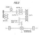
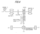
- FIG. 3 and Figure 4 show the arrangement of the power train.
- the disposition of the engine 2 and the motor 1 on the input side of the clutch 3 may comprise the motor 1 being upstream of the engine 2 as shown in Figure 3 or downstream of the engine 2 as shown in Figure 4 .
- the output shaft of the engine 2 is directly connected to the input shaft of the clutch 3.
- the output shaft of the engine 2 is connected to the output shaft of the motor 1 by a belt or a gear.
- the output shaft of the engine 2 is directly connected to the input shaft of the clutch 3 by passing through a rotor of the motor 1.
- the input side of the clutch 3 is formed on a single axis.
- the arrangement of the continuously variable transmission 5 and the motor 4 on the output side of the clutch 3 may comprise the arrangement of the motor 4 upstream of the continuously variable transmission 5 as shown in Figure 3 or the arrangement of the motor 4 downstream of the continuously variable transmission 5 as shown in Figure 4 .
- the output shaft of the clutch 3 is directly connected to the input shaft of the continuously variable transmission 5 by passing through the rotor of the motor 4 and so the output side of the clutch 3 is formed on a single axis.
- the output shaft of the clutch 3 is directly connected to the output shaft of the motor 4 by passing through the input shaft of the continuously variable transmission 5.
- the output side of the clutch 3 is formed by a single axis.
- the motor 4 is connected to the input shaft of the continuously variable transmission 5.
- the arrangement of the power line is not limited to the examples shown in Figure 3 and Figure 4 .
- the engine and motor are connected to the input shaft of the clutch, the input shaft of the continuously variable transmission and the motor are connected to the output shaft of the clutch and there is a drive mechanism which transmits drive force to the drive wheels through a reduction gear and a differential gear unit from the output shaft of the continuously variable transmission, each component may be arranged in any way.
- a clutch 3 and CVT provided a motor and engine and adapt the present invention to a drive mechanism which transmits the torque of both the motor and the engine to drive wheels.
- Figure 5 shows an example of a power train using a toroidal CVT as a continuously variable transmission.
- FIG. 6 is a block diagram showing the control system of the continuously variable transmission 5 and the motors 1, 4 which are controlled by the controller 16.
- the controller 16 realizes drive control as shown in Figure 6 by software disposed in a microcomputer and controls a drive ratio of the continuously variable transmission 5 and the torque of the motors 1, 4 and engine 2.
- a target drive torque tTd in the drive shaft is calculated on the basis of the accelerator pedal aperture aps detected by the accelerator pedal sensor 22 and the vehicle speed Vsp detected by the vehicle speed sensor 24. More precisely, a map of target drive torques tTd with respect to accelerator pedal aperture aps and vehicle speed Vsp is preset. Thus the target drive torque tTd is calculated corresponding to a detected value with respect to accelerator pedal aperture aps and vehicle speed Vsp by the sensor 22, 24 based on the map. A negative torque when the vehicle is coasting is included in the target drive torque tTd .
- a generator torque tTg of the drive shaft conversion calculated from the vehicle speed Vsp and the tire radius R is calculated based on the work ratio tPg of the required electricity generation amount calculated on the basis of the SOC of the main battery 15.
- a target input rotation speed tNi of the continuously variable transmission 5 is calculated based on the target drive torque tTd , vehicle speed Vsp and the addition value vtTd of adding the target drive torque tTd and generator torque tTg .
- a map of target input rotation speed tNi is preset with respect to target drive torque tTd , vehicle speed Vsp and the addition value vtTd and calculated on the basis of the map.
- the continuously variable transmission 5 regulates the drive ratio based on the target input rotation speed tNi .
- a target input torque tTe in the input shaft of the continuously variable transmission 5 is calculated from the real drive ratio rG of the continuously variable transmission 5, the final reduction ratio Gf of the differential gear 7 and the reduction gear 6 based on the addition value vtTd of the generator torque tTg and the target drive torque tTd.
- An inertial correction torque of the engine 2 that is to say, a torque Ti to accelerate the rotation speed of the engine 2 to a target input rotation speed tNi is added to the target input torque tTe .
- a target input torque tTs in the input shaft of the continuously variable transmission 5 is calculated.
- the engine 2 is controlled to a target engine torque in order to generate a target input torque tTs by the engine 2.
- a real engine torque Te is estimated considering the delay of the engine 2 by limiting the maximum engine torque Temax and minimum torque Temin with respect to the current engine rotation speed Ne .
- the method of estimating the real engine torque Te comprises
- the deficit ( tTs - Te ) of the engine torque is calculated by subtracting an estimated real engine torque Te from a target input torque tTs .
- a generator torque tTgi in the input shaft of the continuously variable transmission 5 is calculated from a real drive ratio rG of the continuously variable transmission 5 and the final reduction ratio Gf of the differential gear 7 and the reduction gear 6 based on the generator torque tTg in the drive shaft.
- a target torque tTm of the motor 4 is calculated by subtracting a generator torque tTgi from an engine torque deficit ( tTs - Te ).
- Adjusting the drive force control above comprises calculating a target drive torque based on a vehicle speed and an accelerator pedal aperture, calculating a generator torque from the motor based on the a SOC of the battery and controlling an engine on the basis of a target engine torque representing an addition value of a target drive torque and a generator torque.
- the motor is controlled by a target motor torque representing a difference between a target drive torque and an engine torque estimation value.
- the motor functions as a generator to charge the battery.
- a target input torque tTs is generated by the engine 2.
- a torque is generated by the motor 4 as a target motor torque tTm .
- generation of electricity is performed by the other motor 1 or is required, generation of electricity is not performed by the motor 1 and the amount of engine assist due to the motor 4 is decreased to that degree.
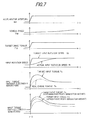
- Figure 7 is a time chart showing control characteristics during acceleration.
- the accelerator pedal aperture aps is increased by depressing the acceleration pedal during running.
- the target drive torque tTd in the drive shaft is increased and the target input rotation speed tNi of the continuously variable transmission 5 is increased in order to realize a target drive torque tTd at that vehicle speed Vsp .
- a target input torque tTe is calculated from a target drive torque tTd based on a real input rotation speed Ni (actual drive ratio rG ) of the continuously variable transmission 5. Furthermore a target input torque tTs is calculated by adding a torque Ti of the inertial correction value due to variable control.
- the engine 2 is controlled by a target input torque tTs as a target engine torque, there is a limit to engine torque.
- a target input torque tTe is calculated from the addition amount vtTd of the target drive torque tTd and the generator torque tTg based on a real input rotation number Ni (actual drive ratio rG ) of the continuously variable transmission 5.
- a target input torque tTs is calculated by adding an inertial torque correction amount Ti due to variable control.
- the engine 2 basically is controlled to a target input torque tTs as a target engine torque.
- a target engine torque exceeds a maximum value or there is a response delay in reaching an engine torque
- a generator torque of the engine 2 may be diverted to a drive component by reducing the generator amount of the motor 1.
- the engine 2 may be assisted by the motor 4.
- electricity generation by the motor 1 may be recommenced by terminating the engine assist of the motor 4.
- Figure 8 to Figure 11 show the simulation result of control characteristics under different running conditions.
- Figure 8 shows the result of depressing the acceleration pedal when the vehicle is running at 30 km/h with a generator amount of 0.
- Figure 9 shows the result of depressing the acceleration pedal when the vehicle is running at 30 km/h with a generator amount of 10kw.
- Figure 10 shows the result of depressing the acceleration pedal when the vehicle is running at 30 km/h with a generator amount of 0 and subsequently releasing the acceleration pedal.
- Figure 11 shows the result of depressing the acceleration pedal when the vehicle is running at 30 km/h with a generator amount of 10kw and subsequently releasing the accelerator pedal.
- the real engine torque Te is created by a response delay with respect to the target engine torque and is rapidly assisted by an assist torque Tm due to the motor 4 and the vehicle varies speed by the total torque of these two values Te + Tm .
- the motors 1 and 4 When the generator amount takes a value of 0, the motors 1 and 4 generate an acceleration force when the accelerator pedal is depressed. When the accelerator pedal is released, a braking assist force is generated by electricity generation from braking energy. Furthermore when 10kw electricity generation is performed by the motor 1 and 4, an acceleration assist force is generated by suspending electricity generation while the accelerator pedal is depressed. Braking assist is performed by generating electricity by generating a regenerative braking force on the accelerator pedal is released.
- a target input torque tTs is taken to be a target engine torque.
- an advance correction may be applied to a target input torque tTs as the target engine torque.
- an advance correction may be applied by adding a value ( k.d*dtTs / dt ) which corresponds to the differential value of the target input torque to the target input torque tTs .
- sections other than those which apply an advance correction to the target input torque tTs as a target engine torque are the same as the control block diagram shown in Figure 6 and so are omitted from the drawing.
- a retard correction may be applied to the target motor torque Tm .
- the target input torque tTs may be used without modification as a target engine torque.
- An engine torque deficit may be calculated by subtracting real engine torque Te from the value tTs ' which represents a linear response correction applied to a target input torque tTs .
- a target motor torque tTm is calculated by subtracting a generator torque tTgi from the engine torque deficit ( tTs ' - Te )
- the above embodiment was desclosed on the basis of a hybrid vehicle using two motors (motors 1 and 4).
- the present invention can be applied to a hybrid vehicle using a single motor.
- the motor doubles as both a generator and an engine assist.
- generation of electricity may be suspended and the generator component of engine torque may be diverted to a drive component.
- an assist may be performed by the motor.
- the following method may be applied.
Landscapes
- Engineering & Computer Science (AREA)
- Chemical & Material Sciences (AREA)
- Combustion & Propulsion (AREA)
- Transportation (AREA)
- Mechanical Engineering (AREA)
- Power Engineering (AREA)
- Automation & Control Theory (AREA)
- Hybrid Electric Vehicles (AREA)
- Electric Propulsion And Braking For Vehicles (AREA)
- Control Of Vehicle Engines Or Engines For Specific Uses (AREA)
- Control Of Driving Devices And Active Controlling Of Vehicle (AREA)
- Electrical Control Of Air Or Fuel Supplied To Internal-Combustion Engine (AREA)
- Control Of Transmission Device (AREA)
Description
- The present invention relates to a drive power control device for a hybrid vehicle. In particular, the invention relates to improvements to the control of drive power distribution of an engine and a motor.
- A hybrid vehicle which runs on the drive power of an engine and a motor is known. A motor in such a hybrid vehicle is operated by the electrical power of a battery. A large drive force is obtained by operating both the engine and the motor at the same time when, for example, the vehicle is accelerating. When the charge of the battery is low, the motor functions as a generator. The battery is charged by the motor being driven by the engine to generate electricity.
- However when the vehicle is running on the drive force of both the engine and the motor, in consideration of operating conditions such as generation of electricity by the motor, speed change control by the transmission or the response of the engine, it is necessary to control the motor and the engine cooperatively so that the response and overall effect of vehicle operation is optimized.
-
US 5,806,617 discloses a hybrid vehicle comprising an engine and a generator/motor controlled by a control device. This control device receives data from an accelerator sensor, a vehicle speed sensor and a battery sensor, which are connected to a battery. -
EP 0 800 945 A2 discloses a control system for a hybrid vehicle including an engine, a motor and a battery. Further disclosed is a speed sensor and an accelerator sensor. The state of charge is detected by a current/voltage sensor. -
JP 05229351 - It is an object of the present invention to improve the response and overall effect of vehicle operation when running on the drive force of both the engine and the motor.
- The object is achieved by the features of
independent claims - The details as well as other features and advantages of the invention are set forth in the remainder of the specification and are shown in the accompanying drawings.
-
-
Figure 1 is an overall view of a first embodiment of the present invention. -
Figure 2 is a partial view ofFigure 1 . -
Figure 3 shows an example of the disposition of a power line. -
Figure 4 shows another example of the disposition of a power line. -
Figure 5 shows yet another example of the disposition of a power line. -
Figure 6 is a block diagram showing a control system of a continuously variable transmission, an engine and a motor. -
Figure 7 is an explanatory view showing the control characteristics of a continuously variable transmission, an engine and a motor during acceleration. -
Figure 8 shows a simulation result of control according to the present invention. -
Figure 9 is similar toFigure 8 but shows a simulation result of control according to another parameter. -
Figure 10 is similar toFigure 8 but shows yet another simulation result of control according to another parameter. -
Figure 11 is similar toFigure 8 but shows yet another simulation result of control according to another parameter. -
Figure 12 is a partial block diagram of another embodiment of a control system for a continuously variable transmission, an engine and a motor. -
Figure 13 is a partial block diagram of yet another embodiment of a control system for a continuously variable transmission, an engine and a motor. - In
Figure 1 , the thick line represents the transmission pathway of mechanical force. The thick broken line shows electrical force, the thin line is a control line and the double line shows oil pressure control. - The power train of the vehicle comprises a
motor 1, anengine 2, aclutch 3, amotor 4, a continuouslyvariable transmission 5, areduction gear 6, adifferential gear 7 anddrive wheels 8. The output shaft of themotor 1, the output shaft of theengine 2 and the input shaft of theclutch 3 are mutually connected. Furthermore the output shaft of theclutch 3, the output shaft of themotor 4 and the input shaft of the continuouslyvariable transmission 5 are mutually connected. - When the
clutch 3 is engaged, theengine 2 and themotor 4 become the source of drive power of the vehicle. When theclutch 3 is released, only themotor 4 is the source of drive power of the vehicle. The drive force of theengine 2 and/or themotor 4 is transmitted to the drive wheels through the continuouslyvariable transmission 5, thereduction gear 6 and thedifferential gear 7. A drive ratio in the continuouslyvariable transmission 5 is varied on the basis of an oil pressure supplied from an oil pressure control device. An oil pump (not shown) of the oilpressure control device 9 is driven by amotor 10. - The
motors motor 1 is used mainly to start the engine and to generate electricity. Themotor 4 is used mainly to drive and brake the vehicle. Themotor 10 is used to drive the oil pump of the oilpressure control device 9. Themotors clutch 3 is engaged, it is possible to use themotor 1 to drive and brake the vehicle and use themotor 4 to start the engine and generate electricity. - The
clutch 3 is a powder clutch which can regulate the size of the transmitted torque. A single dry type clutch or a multiple wet type clutch may be used as a clutch. The continuouslyvariable transmission 5 is a toroidal or a belt-type continuously variable transmission in which a drive ratio may be continuously varied. - The
motors inverters motor main battery 15 through a common DC link 14. Direct current electrical power from themain battery 15 is converted to an alternating current and supplied to themotor motors - Since the
inverters 11 ∼ 13 are mutually connected through the DC link 14, it is possible to supply electrical power generated by the motor during regenerative operation directly to the other motor during running without passing themain battery 15. - It is possible to use all kinds of batteries such as lithium, ion batteries, nickel batteries, hydrogen batteries and lead batteries or an electric motor double capacitor, the so-called "power capacitor" as the main battery.
- The
controller 16 is provided with a microcomputer, related components and various actuators. Thecontroller 16 controls the output torque or rotation speed of theengine 2, the transmission torque of theclutch 3, the output torque or rotation speed of themotor variable transmission 5. - As shown in
Figure 2 , theengine key switch 20, the transmissionselect lever switch 21, theaccelerator sensor 22, thebrake switch 23, thevehicle speed sensor 24, thebattery temperature sensor 25, the battery state-of-charge (hereafter SOC)detection device 26, theengine rotation sensor 27 and thethrottle aperture sensor 28 are connected to thecontroller 16, - The engine
key switch 20 is placed in the ON position by setting the vehicle key in the ON or the START position. The transmissionselect lever switch 21 places the P, N, R, D switches in the ON position in response to placing the transmission select lever position to parking P, neutral N, reverse R and drive D. - The
accelerator sensor 22 detects the amount of depression aps (hereafter accelerator aperture) of the accelerator pedal. Thebrake switch 23 detects the state of depression (here "switch ON") of the brake pedal. Thevehicle speed sensor 24 detects the running speed Vsp of the vehicle. Thebattery temperature sensor 25 detects the temperature Tb of themain battery 15. The batterySOC detection device 26 detects the SOC (state of charge) of themain battery 15. Theengine rotation sensor 27 detects the rotation speed Ne of theengine 2 and thethrottle aperture sensor 28 detects the throttle valve aperture θth of theengine 2. - The
controller 16 is connected to thefuel injection device 30 of theengine 2, theignition device 31, the valuetiming regulation device 32 and the like. Thecontroller 16 controls thefuel injection device 30 and regulates the fuel injection amount as well as the termination and supply of fuel to theengine 2. Theignition device 31 is controlled to perform ignition of theengine 2. Thecontroller 16 controls the valvetiming regulation device 32 and the closure period of the air intake valve of theengine 2. Thecontroller 16 is supplied with a low voltage power source by theauxiliary battery 33. -
Figure 3 andFigure 4 show the arrangement of the power train. - The disposition of the
engine 2 and themotor 1 on the input side of the clutch 3 may comprise themotor 1 being upstream of theengine 2 as shown inFigure 3 or downstream of theengine 2 as shown inFigure 4 . - In the arrangement shown in
Figure 3 , the output shaft of theengine 2 is directly connected to the input shaft of theclutch 3. At the same time, the output shaft of theengine 2 is connected to the output shaft of themotor 1 by a belt or a gear. In the arrangement shown inFigure 4 , the output shaft of theengine 2 is directly connected to the input shaft of the clutch 3 by passing through a rotor of themotor 1. Thus the input side of the clutch 3 is formed on a single axis. - The arrangement of the continuously
variable transmission 5 and themotor 4 on the output side of the clutch 3 may comprise the arrangement of themotor 4 upstream of the continuouslyvariable transmission 5 as shown inFigure 3 or the arrangement of themotor 4 downstream of the continuouslyvariable transmission 5 as shown inFigure 4 . In the arrangement shown inFigure 3 , the output shaft of the clutch 3 is directly connected to the input shaft of the continuouslyvariable transmission 5 by passing through the rotor of themotor 4 and so the output side of the clutch 3 is formed on a single axis. In the arrangement shown inFigure 4 , the output shaft of the clutch 3 is directly connected to the output shaft of themotor 4 by passing through the input shaft of the continuouslyvariable transmission 5. Thus the output side of the clutch 3 is formed by a single axis. In either case, themotor 4 is connected to the input shaft of the continuouslyvariable transmission 5. - The arrangement of the power line is not limited to the examples shown in
Figure 3 andFigure 4 . As long as the engine and motor are connected to the input shaft of the clutch, the input shaft of the continuously variable transmission and the motor are connected to the output shaft of the clutch and there is a drive mechanism which transmits drive force to the drive wheels through a reduction gear and a differential gear unit from the output shaft of the continuously variable transmission, each component may be arranged in any way. Furthermore it is possible to omit aclutch 3 and CVT, provided a motor and engine and adapt the present invention to a drive mechanism which transmits the torque of both the motor and the engine to drive wheels. -
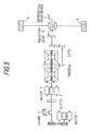
Figure 5 shows an example of a power train using a toroidal CVT as a continuously variable transmission. - Even when a toroidal CVT is used as a continuously
variable transmission 5, either themotor 4 or the toroidal CVT may be arranged on theclutch side 3. However in either case, themotor 4 is connected to the input shaft of the continuouslyvariable transmission 5. -
Figure 6 is a block diagram showing the control system of the continuouslyvariable transmission 5 and themotors controller 16. - The
controller 16 realizes drive control as shown inFigure 6 by software disposed in a microcomputer and controls a drive ratio of the continuouslyvariable transmission 5 and the torque of themotors engine 2. - Firstly, a target drive torque tTd in the drive shaft is calculated on the basis of the accelerator pedal aperture aps detected by the
accelerator pedal sensor 22 and the vehicle speed Vsp detected by thevehicle speed sensor 24. More precisely, a map of target drive torques tTd with respect to accelerator pedal aperture aps and vehicle speed Vsp is preset. Thus the target drive torque tTd is calculated corresponding to a detected value with respect to accelerator pedal aperture aps and vehicle speed Vsp by thesensor - A generator torque tTg of the drive shaft conversion calculated from the vehicle speed Vsp and the tire radius R is calculated based on the work ratio tPg of the required electricity generation amount calculated on the basis of the SOC of the
main battery 15. - A target input rotation speed tNi of the continuously
variable transmission 5 is calculated based on the target drive torque tTd, vehicle speed Vsp and the addition value vtTd of adding the target drive torque tTd and generator torque tTg. - More precisely, a map of target input rotation speed tNi is preset with respect to target drive torque tTd, vehicle speed Vsp and the addition value vtTd and calculated on the basis of the map. The continuously
variable transmission 5 regulates the drive ratio based on the target input rotation speed tNi. - A target input torque tTe in the input shaft of the continuously
variable transmission 5 is calculated from the real drive ratio rG of the continuouslyvariable transmission 5, the final reduction ratio Gf of thedifferential gear 7 and thereduction gear 6 based on the addition value vtTd of the generator torque tTg and the target drive torque tTd. An inertial correction torque of theengine 2, that is to say, a torque Ti to accelerate the rotation speed of theengine 2 to a target input rotation speed tNi is added to the target input torque tTe. Thus a target input torque tTs in the input shaft of the continuouslyvariable transmission 5 is calculated. Basically, theengine 2 is controlled to a target engine torque in order to generate a target input torque tTs by theengine 2. - In contrast to the target input torque tTs, a real engine torque Te is estimated considering the delay of the
engine 2 by limiting the maximum engine torque Temax and minimum torque Temin with respect to the current engine rotation speed Ne. - The method of estimating the real engine torque Te comprises
- 1. A method of estimating the real engine torque Te from an engine torque map with respect to engine rotation number and throttle aperture.
- 2. A method of estimating an engine torque in real time by detecting a cylinder inner pressure (combustion pressure) of the engine.
- 3. A method of estimating an engine torque based on an engine rotation speed and air intake amount of the engine.
- The deficit (tTs - Te) of the engine torque is calculated by subtracting an estimated real engine torque Te from a target input torque tTs.
- A generator torque tTgi in the input shaft of the continuously
variable transmission 5 is calculated from a real drive ratio rG of the continuouslyvariable transmission 5 and the final reduction ratio Gf of thedifferential gear 7 and thereduction gear 6 based on the generator torque tTg in the drive shaft. A target torque tTm of themotor 4 is calculated by subtracting a generator torque tTgi from an engine torque deficit (tTs - Te). - Adjusting the drive force control above comprises calculating a target drive torque based on a vehicle speed and an accelerator pedal aperture, calculating a generator torque from the motor based on the a SOC of the battery and controlling an engine on the basis of a target engine torque representing an addition value of a target drive torque and a generator torque. The motor is controlled by a target motor torque representing a difference between a target drive torque and an engine torque estimation value.
- Thus when the value of the target motor torque is positive, the deficit of the engine torque is corrected by the motor output. When the value is negative, the motor functions as a generator to charge the battery.
- As shown above, basically a target input torque tTs is generated by the
engine 2. However when there is a deficit in the absolute value of the output of the engine during transitional running condition for example, or when there is a deficit in the output due to a response delay, a torque is generated by themotor 4 as a target motor torque tTm. When the output of theengine 2 is assisted by generating a torque by themotor 4 but on the other hand generation of electricity is performed by theother motor 1 or is required, generation of electricity is not performed by themotor 1 and the amount of engine assist due to themotor 4 is decreased to that degree. - In this way, it is possible to divert a real engine torque Te to a drive component of the vehicle from an electricity generating component. This has the same effect as assisting the
engine 2 by generating a torque from themotor 4. - When the
engine 2 is assisted by generating a torque from themotor 4 while generating electricity with themotor 1, energy loss is increased by generator loss from themotor 1 and drive power loss from themotor 4. However when theengine 2 is assisted by themotor 4, it is possible to reduce generator loss from themotor 1 and drive power loss from themotor 4 by reducing the assist amount of themotor 4 by not generating electricity with themotor 1. Thus overall efficiency can be improved. - According to the drive control method of the present embodiment, as desclosed above, it is possible to satisfy the required generator amount and drive force during steady-state running and efficiently assist the deficit of engine torque during transitional running with the motor.
-
Figure 7 is a time chart showing control characteristics during acceleration. - The accelerator pedal aperture aps is increased by depressing the acceleration pedal during running. Thus the target drive torque tTd in the drive shaft is increased and the target input rotation speed tNi of the continuously
variable transmission 5 is increased in order to realize a target drive torque tTd at that vehicle speed Vsp. - When a generator torque tTg has the
value 0, a target input torque tTe is calculated from a target drive torque tTd based on a real input rotation speed Ni (actual drive ratio rG) of the continuouslyvariable transmission 5. Furthermore a target input torque tTs is calculated by adding a torque Ti of the inertial correction value due to variable control. - Basically, although the
engine 2 is controlled by a target input torque tTs as a target engine torque, there is a limit to engine torque. - Furthermore since there is a response delay, when there is a difference between target input torque tTs and a real engine torque Te, the difference is taken to be a target motor torque tTm and the
engine 2 is assisted by themotor 4. - On the other hand, when generation of electricity is required and the generator torque tTg does not have the value of 0, a target input torque tTe is calculated from the addition amount vtTd of the target drive torque tTd and the generator torque tTg based on a real input rotation number Ni (actual drive ratio rG) of the continuously
variable transmission 5. A target input torque tTs is calculated by adding an inertial torque correction amount Ti due to variable control. - Similar to the situation in which no generation of electricity is required, the
engine 2 basically is controlled to a target input torque tTs as a target engine torque. However since a target engine torque exceeds a maximum value or there is a response delay in reaching an engine torque, when only the engine torque is insufficient, firstly a generator torque of theengine 2 may be diverted to a drive component by reducing the generator amount of themotor 1. When the drive torque is still insufficient, theengine 2 may be assisted by themotor 4. Once the real engine torque Te exceeds a target input torque tTs - tTgi (not including the generator torque), electricity generation by themotor 1 may be recommenced by terminating the engine assist of themotor 4. -
Figure 8 to Figure 11 show the simulation result of control characteristics under different running conditions. -
Figure 8 shows the result of depressing the acceleration pedal when the vehicle is running at 30 km/h with a generator amount of 0.Figure 9 shows the result of depressing the acceleration pedal when the vehicle is running at 30 km/h with a generator amount of 10kw.Figure 10 shows the result of depressing the acceleration pedal when the vehicle is running at 30 km/h with a generator amount of 0 and subsequently releasing the acceleration pedal.Figure 11 shows the result of depressing the acceleration pedal when the vehicle is running at 30 km/h with a generator amount of 10kw and subsequently releasing the accelerator pedal. - The real engine torque Te is created by a response delay with respect to the target engine torque and is rapidly assisted by an assist torque Tm due to the
motor 4 and the vehicle varies speed by the total torque of these two values Te+Tm. - However the real drive torque Td in the drive shaft undergoes a response delay on comparison with a target drive force tTd since creation of an actual input rotation speed Ni in the continuously
variable transmission 5 undergoes a response delay. - When the generator amount takes a value of 0, the
motors motor - The above embodiment was desclosed on the basis that a target input torque tTs is taken to be a target engine torque. However an advance correction may be applied to a target input torque tTs as the target engine torque. For example, as shown in
Figure 12 , an advance correction may be applied by adding a value (k.d*dtTs/dt) which corresponds to the differential value of the target input torque to the target input torque tTs. InFigure 12 , sections other than those which apply an advance correction to the target input torque tTs as a target engine torque are the same as the control block diagram shown inFigure 6 and so are omitted from the drawing. - In this way, the drive component of the
engine 2 during acceleration is increased, and conversely the generation amount may be reduced by reducing the drive component of the main battery andmotor 4. Thus it is possible to increase overall efficiency. - Instead of applying a motive correction to the target input torque tTs as a target engine torque, a retard correction may be applied to the target motor torque Tm. For example, as shown in
Figure 13 , the target input torque tTs may be used without modification as a target engine torque. An engine torque deficit may be calculated by subtracting real engine torque Te from the value tTs' which represents a linear response correction applied to a target input torque tTs. Furthermore a target motor torque tTm is calculated by subtracting a generator torque tTgi from the engine torque deficit (tTs' - Te) - It is desirable that the response retard correction controls the vehicle drive system in a balanced manner (to prevent resonance). In
Figure 13 , section other than those which apply a retard correction to the target motor torque are the same as those shown in the control block diagram inFigure 6 and so are omitted from the figure. - In this way, the drive component is increased by the
engine 2 during acceleration and conversely the generation amount is reduced by reducing the drive component of the main battery andmotor 4. Thus it is possible to increase overall efficiency. - The above embodiment was desclosed on the basis of a hybrid vehicle using two motors (
motors 1 and 4). However the present invention can be applied to a hybrid vehicle using a single motor. In such a case, the motor doubles as both a generator and an engine assist. During generation of electricity or when generation is required and an engine assist is performed, generation of electricity may be suspended and the generator component of engine torque may be diverted to a drive component. Subsequently when the engine torque is still deficient, an assist may be performed by the motor. - In this way, the same effect may be obtained as in a hybrid vehicle with two separate motors.
- When the assist amount of the motor can not be maintained due to reductions in the SOC of the main battery or the motor overheating, the following method may be applied.
- 1. The air-fuel ratio may be temporarily enriched when the target engine torque is created thus advancing the creation of the engine torque.
- 2. The drive correction with respect to the target input torque tTs may be increased thus advancing the creation of the engine torque.
- Although the invention has been described above by reference to certain embodiments of the invention, the invention is not limited to the embodiments described above. Modifications and variations of the embodiments described above will within
- the scope of the invention as defined in the following claims.
Claims (14)
- A drive power control device for a hybrid vehicle running by the drive power of an engine (2) and/or a motor (1, 4) comprising:- an accelerator sensor (22) detecting a depression amount of an accelerator pedal,- a vehicle speed sensor (24) detecting a vehicle speed (Vsp),- a battery (15) performing storage and output of electrical force with said motors (1, 4),- a battery sensor (26) detecting the state of charge of said battery (15) and- a controller (16) controlling said engine (2) and said motor (1, 4), wherein said controller (16) is adapted for:- calculating a target drive torque (tTd) based on said vehicle speed (Vsp) detection value and said accelerator pedal depression amount value,- calculating a generator torque (tTgi) of said motor (1, 4) based on said state of charge detected value, and- controlling said engine (2) to obtain said target drive torque (tTd) and said generator torque (tTgi) as a target engine torque in order to generate a target input torque (tTs) in the input shaft of a transmission, characterized by- estimating an real engine torque (Te) of said engine (2), and- controlling said motor (1, 4) to a target motor torque (tTm), wherein the target motor torque (tTm) is calculated by subtracting the generator torque (tTgi) from an engine torque deficit (tTs-Te), and wherein the engine torque deficit (tTs-Te) is calculated by subtracting the estimated real engine torque (Te) from the target input torque (tTs), and if an engine torque deficit (tTs-Te) is calculated, the motor (1, 4) stops or reduces to generate electricity and the motor (1, 4) generates a torque with the target motor torque (tTm).
- A drive power control device for a hybrid vehicle according to claim 1 wherein- said controller(16) is adapted for controlling an output of said motor (1, 4) to assist the rotation of said engine (2) when said target input torque (tTs) is greater than said real engine torque (Te) and controls a generation of electricity by said motor (1, 4) when said target input torque (tTs) is smaller than said real engine torque (Te).
- A drive power control device for a hybrid vehicle according to claim 1 wherein- said controller (16) is adapted for controlling said engine (2) by applying a differential correction to said target input torque (tTs).
- A drive power control device for a hybrid vehicle according to claim 1 wherein- said controller(16) is adapted for controlling said motor (1, 4) by the difference of a value of applying a delay correction value to said target drive torque (tTd) and said real engine torque (Te) as a target motor torque (tTm).
- A drive power control device for a hybrid vehicle according to claim 4 wherein- said controller (16) is adapted for performing the delay correction on said target input torque (tTs) to suppress resonance of the vehicle drive system.
- A drive power control device for a hybrid vehicle according to claim 1 wherein- said controller (16) is adapted for adding an inertial correction torque accompanying variable control in a transmission to said target drive torque (tTd).
- A drive power control device for a hybrid vehicle according to claim 1 wherein- said controller (16) is adapted for further determining whether or not to output said target motor torque (tTm) by said motor (1, 4) based on a condition of said motor (1,4) and said detected state of charge value of said battery (15), and- enriches an air-fuel ratio temporarily to achieve said target input torque (tTs) when it is determined not to output said target motor torque(tTm).
- A drive power control device for a hybrid vehicle running by the drive power of an engine (2) and/or a motor (1, 4) comprising:- a first motor (1) and a second motor (4),- an accelerator sensor (22) detecting a depression amount of an accelerator pedal,- a vehicle speed sensor (24) detecting a vehicle speed (Vsp),- a battery (15) performing storage and output of electrical force with said motors (1, 4),- a battery sensor (26) detecting the state of charge of said battery (15) and- a controller (16) controlling said engine (2) and said motors (1, 4), wherein said controller (16) is adapted for:- calculating a target drive torque (tTd) based on said vehicle speed (Vsp) detection value and said accelerator pedal depression amount value,- calculating a generator torque (tTgi) of said first motor (1) based on said state of charge detected value, and- controlling said engine (2) to obtain said target drive torque (tTd) and said generator torque (tTgi) as a target engine torque in order to generate a target input torque (tTs) in the input shaft of a transmission, characterized by- estimating an real engine torque (Te) of said engine (2), and- controlling said second motor (4) to a target motor torque (tTm), wherein the target motor torque (tTm) is calculated by subtracting the generator torque (tTgi) from an engine torque deficit (tTs-Te), and wherein the engine torque deficit (tTs-Te) is calculated by subtracting the estimated real engine torque (Te) from the target input torque (tTs), and if an engine torque deficit (tTs-Te) is calculated, the first motor (1) stops or reduces to generate electricity and the second motor (4) generates a torque with the target motor torque (tTm).
- A drive power control device for a hybrid vehicle according to claim 8 wherein- said controller (16) is adapted for controlling an output of said second motor (4) to assist the rotation of said engine (2) when said target input torque (tTs) is greater than said real engine torque (Te) and controls a generation of electricity by said first motor (1) when said target input torque (tTs) is smaller than said real engine torque (Te).
- A drive power control device for a hybrid vehicle according to claim 8 wherein- said controller (16) is adapted for controlling said engine (2) by applying a differential correction to said target input torque (tTs).
- A drive power control device for a hybrid vehicle according to claim 8 wherein- said controller (16) is adapted for controlling said motors (1, 4) by the difference of a value of applying a delay correction value to said target drive torque (tTd) and said real engine torque (Te) as a target motor torque (tTm).
- A drive power control device for a hybrid vehicle according to claim 11 wherein- said controller (16) is adapted for performing the delay correction on said target input torque (tTs) to suppress resonance of the vehicle drive system.
- A drive power control device for a hybrid vehicle according to claim 8 wherein- said controller (16) is adapted for adding an inertial correction torque accompanying variable control in a transmission to said target drive torque (tTd).
- A drive power control device for a hybrid vehicle according to claim 8 wherein- said controller (16) is adapted for further determining whether or not to output said target motor torque (tTm) by said second motor (4) based on a condition of said second motor (4) and said detected state of charge value of said battery (15), and- enriches an air-fuel ratio temporarily to achieve said target input torque (tTs) when it is determined not to output said target motor torque (tTm).
Applications Claiming Priority (2)
| Application Number | Priority Date | Filing Date | Title |
|---|---|---|---|
| JP15486398A JP3451935B2 (en) | 1998-06-03 | 1998-06-03 | Driving force control device for hybrid vehicle |
| JP15486398 | 1998-06-03 |
Publications (3)
| Publication Number | Publication Date |
|---|---|
| EP0962352A2 EP0962352A2 (en) | 1999-12-08 |
| EP0962352A3 EP0962352A3 (en) | 2000-04-05 |
| EP0962352B1 true EP0962352B1 (en) | 2011-04-27 |
Family
ID=15593574
Family Applications (1)
| Application Number | Title | Priority Date | Filing Date |
|---|---|---|---|
| EP99110638A Expired - Lifetime EP0962352B1 (en) | 1998-06-03 | 1999-06-02 | Drive power control device for hybrid vehicle |
Country Status (4)
| Country | Link |
|---|---|
| US (1) | US6233508B1 (en) |
| EP (1) | EP0962352B1 (en) |
| JP (1) | JP3451935B2 (en) |
| DE (1) | DE69943387D1 (en) |
Families Citing this family (108)
| Publication number | Priority date | Publication date | Assignee | Title |
|---|---|---|---|---|
| EP1142744A4 (en) * | 1998-12-01 | 2003-08-27 | Hitachi Ltd | DRIVE DEVICE AND VEHICLE |
| JP2000257462A (en) * | 1999-03-09 | 2000-09-19 | Honda Motor Co Ltd | Engine control device for hybrid vehicle |
| JP3395708B2 (en) * | 1999-04-27 | 2003-04-14 | 株式会社日立製作所 | Hybrid vehicle |
| JP3926519B2 (en) * | 1999-08-30 | 2007-06-06 | 本田技研工業株式会社 | Hybrid vehicle |
| JP4480862B2 (en) * | 1999-09-07 | 2010-06-16 | 本田技研工業株式会社 | Control device for hybrid vehicle |
| JP3746644B2 (en) * | 1999-09-16 | 2006-02-15 | 本田技研工業株式会社 | Control device for hybrid vehicle |
| JP3810601B2 (en) * | 1999-11-25 | 2006-08-16 | 本田技研工業株式会社 | Hybrid vehicle lubrication structure |
| JP3403690B2 (en) * | 2000-03-02 | 2003-05-06 | 株式会社日立製作所 | Hybrid electric vehicle using permanent magnet type rotating electric machine |
| JP3736268B2 (en) * | 2000-03-21 | 2006-01-18 | 日産自動車株式会社 | Control device for hybrid vehicle |
| JP3654128B2 (en) * | 2000-04-06 | 2005-06-02 | 日産自動車株式会社 | Vehicle control device |
| US7004273B1 (en) * | 2000-04-26 | 2006-02-28 | Robert Gruenwald | Hybrid electric vehicle |
| US6484830B1 (en) * | 2000-04-26 | 2002-11-26 | Bowling Green State University | Hybrid electric vehicle |
| US7252165B1 (en) * | 2000-04-26 | 2007-08-07 | Bowling Green State University | Hybrid electric vehicle |
| JP3903918B2 (en) * | 2000-07-11 | 2007-04-11 | アイシン・エィ・ダブリュ株式会社 | Drive device |
| US6379281B1 (en) * | 2000-09-08 | 2002-04-30 | Visteon Global Technologies, Inc. | Engine output controller |
| JP2002089687A (en) * | 2000-09-18 | 2002-03-27 | Aisin Aw Co Ltd | Control device for hybrid vehicle |
| US6441574B1 (en) * | 2000-10-27 | 2002-08-27 | Ford Motor Company | Energy control strategy for a hybrid electric vehicle |
| JP3573202B2 (en) * | 2000-11-06 | 2004-10-06 | 三菱自動車工業株式会社 | Hybrid vehicle torque control device |
| JP3815220B2 (en) * | 2000-12-27 | 2006-08-30 | アイシン・エィ・ダブリュ株式会社 | Hybrid vehicle and control method thereof |
| JP3876729B2 (en) * | 2001-03-08 | 2007-02-07 | アイシン・エィ・ダブリュ株式会社 | HYBRID VEHICLE DRIVE CONTROL DEVICE, CONTROL METHOD FOR HYBRID VEHICLE DRIVE DEVICE, AND PROGRAM THEREOF |
| US6837323B2 (en) | 2001-06-18 | 2005-01-04 | Visteon Global Technologies Inc. | Variable shift schedule control |
| US6581705B2 (en) * | 2001-06-29 | 2003-06-24 | Ford Global Technologies, Llc | Method for starting an engine in a parallel hybrid electric vehicle |
| KR20030018924A (en) * | 2001-08-31 | 2003-03-06 | 현대자동차주식회사 | Motor load controlling device of hybrid fuel cell vehicle and method thereof |
| US6553287B1 (en) | 2001-10-19 | 2003-04-22 | Ford Global Technologies, Inc. | Hybrid electric vehicle control strategy to achieve maximum wide open throttle acceleration performance |
| KR100428325B1 (en) * | 2001-12-06 | 2004-04-28 | 현대자동차주식회사 | Hybrid electric vehicle of torque control system |
| KR20030046695A (en) * | 2001-12-06 | 2003-06-18 | 현대자동차주식회사 | Hybrid electric vehicle of engine control system |
| JP3998991B2 (en) * | 2002-02-05 | 2007-10-31 | 本田技研工業株式会社 | Vehicle equipped with electric motor |
| US6842673B2 (en) * | 2002-06-05 | 2005-01-11 | Visteon Global Technologies, Inc. | Engine engagement control for a hybrid electric vehicle |
| KR20040002090A (en) * | 2002-06-29 | 2004-01-07 | 현대자동차주식회사 | Motor controlling apparatus for hybrid electric vehicle and method |
| US6845305B1 (en) | 2002-09-11 | 2005-01-18 | Ford Motor Company | Engine torque control for a hybrid electric vehicle using estimated engine torque |
| JP4102633B2 (en) * | 2002-09-25 | 2008-06-18 | ダイハツ工業株式会社 | Travel drive control device for hybrid vehicle |
| EP1415837A1 (en) * | 2002-10-29 | 2004-05-06 | STMicroelectronics S.r.l. | Parallel configuration system for hybrid vehicles |
| DE10257285A1 (en) * | 2002-12-07 | 2004-06-24 | Robert Bosch Gmbh | Control circuit setting operating point for road vehicle drive-train uses mapping diagram with three-dimensional plot with several degrees of freedom and has several control modules connected together |
| US6777904B1 (en) | 2003-02-25 | 2004-08-17 | Ford Global Technologies, Llc | Method and system for controlling a motor |
| US6831429B2 (en) * | 2003-03-10 | 2004-12-14 | Visteon Global Technologies, Inc. | Prediction of available torque and power from battery-powered traction motor |
| FR2855107B1 (en) * | 2003-05-23 | 2006-06-16 | Renault Sa | METHOD AND DEVICE FOR CONTROLLING A MOTORPROOF GROUP IN TORQUE MODE WITH SEPARATE MECHANICAL AND ELECTRICAL CONTROLS |
| JP4262750B2 (en) * | 2003-05-23 | 2009-05-13 | ルノー・エス・アー・エス | Power system control method and apparatus having separate mechanical and electrical control |
| JP3997955B2 (en) | 2003-06-23 | 2007-10-24 | トヨタ自動車株式会社 | Hybrid vehicle and control method thereof |
| US7143851B2 (en) * | 2003-09-10 | 2006-12-05 | Ford Global Technologies, Llc | Method for controlling a wheel drive system of a hybrid vehicle |
| JP2005138743A (en) * | 2003-11-07 | 2005-06-02 | Nissan Motor Co Ltd | Hybrid vehicle driving force control device |
| JP3743444B2 (en) * | 2003-11-12 | 2006-02-08 | 日産自動車株式会社 | Drive device for hybrid vehicle |
| US7350602B2 (en) * | 2004-07-19 | 2008-04-01 | Ford Global Technologies, Llc | System and method for engine start detection for hybrid vehicles |
| US7267191B2 (en) * | 2004-07-30 | 2007-09-11 | Ford Global Technologies, Llc | System and method for battery protection strategy for hybrid electric vehicles |
| US8061463B2 (en) * | 2004-11-25 | 2011-11-22 | Honda Motor Co., Ltd. | Control system for hybrid vehicle |
| JP4529726B2 (en) * | 2005-02-23 | 2010-08-25 | トヨタ自動車株式会社 | POWER OUTPUT DEVICE, CONTROL METHOD FOR POWER OUTPUT DEVICE, AND VEHICLE WITH THE SAME |
| DE102005015485A1 (en) | 2005-04-05 | 2006-11-30 | Daimlerchrysler Ag | Drive train of a vehicle and method for controlling a drive train |
| JP4337768B2 (en) | 2005-04-25 | 2009-09-30 | トヨタ自動車株式会社 | Vehicle integrated control device |
| DE102005032670A1 (en) * | 2005-07-13 | 2007-02-01 | Iav Gmbh Ingenieurgesellschaft Auto Und Verkehr | Method for controlling the drive power distribution in a motor vehicle with hybrid drive |
| DE102005047940B4 (en) * | 2005-10-06 | 2025-08-07 | Volkswagen Ag | Method and device for torque control of a hybrid motor vehicle |
| US11370302B2 (en) | 2005-11-17 | 2022-06-28 | Invently Automotive Inc. | Electric vehicle power management system |
| US11390165B2 (en) | 2005-11-17 | 2022-07-19 | Invently Automotive Inc. | Electric vehicle power management system |
| US11279233B2 (en) | 2005-11-17 | 2022-03-22 | Invently Automotive Inc. | Electric vehicle power management system |
| US10882399B2 (en) | 2005-11-17 | 2021-01-05 | Invently Automotive Inc. | Electric vehicle power management system |
| US11180025B2 (en) | 2005-11-17 | 2021-11-23 | Invently Automotive Inc. | Electric vehicle power management system |
| US11254211B2 (en) | 2005-11-17 | 2022-02-22 | Invently Automotive Inc. | Electric vehicle power management system |
| US11186173B2 (en) | 2005-11-17 | 2021-11-30 | Invently Automotive Inc. | Electric vehicle power management system |
| US11214144B2 (en) | 2005-11-17 | 2022-01-04 | Invently Automotive Inc. | Electric vehicle power management system |
| US11345236B2 (en) | 2005-11-17 | 2022-05-31 | Invently Automotive Inc. | Electric vehicle power management system |
| US11230190B2 (en) | 2005-11-17 | 2022-01-25 | Invently Automotive Inc. | Electric vehicle power management system |
| US11267338B2 (en) | 2005-11-17 | 2022-03-08 | Invently Automotive Inc. | Electric vehicle power management system |
| US11247564B2 (en) | 2005-11-17 | 2022-02-15 | Invently Automotive Inc. | Electric vehicle power management system |
| DE102005055001A1 (en) * | 2005-11-18 | 2007-05-24 | Bayerische Motoren Werke Ag | Method for determining a drive torque correction factor for the adjustment of cooperating drive torques of various drive devices |
| KR101028022B1 (en) | 2005-12-08 | 2011-04-13 | 현대자동차주식회사 | Boosting system and control method for motor control of hybrid vehicle |
| KR101063563B1 (en) | 2005-12-12 | 2011-09-07 | 현대자동차주식회사 | How to Optimize Engine Operating Point for Hybrid Vehicles |
| DE102005060858A1 (en) | 2005-12-20 | 2007-06-28 | Robert Bosch Gmbh | Method for operating a hybrid vehicle |
| DE102006006107A1 (en) * | 2006-02-10 | 2007-08-16 | Robert Bosch Gmbh | Method for operating a drive device of a hybrid vehicle |
| US7527028B2 (en) * | 2006-03-09 | 2009-05-05 | Ford Global Technologies, Llc | Hybrid vehicle system having engine with variable valve operation |
| JP4059283B2 (en) * | 2006-08-25 | 2008-03-12 | トヨタ自動車株式会社 | Vehicle control apparatus, hybrid vehicle, vehicle control method, program for causing computer to execute vehicle control method, and computer-readable recording medium recording the program |
| DE102006045502A1 (en) * | 2006-09-27 | 2008-04-03 | Jungheinrich Ag | Device for controlling a hybrid drive system for a motor vehicle, in particular an industrial truck |
| FR2907744B1 (en) * | 2006-10-26 | 2009-05-08 | Renault Sas | METHOD AND DEVICE FOR CONTROLLING THE ELECTRICAL LOAD OF A BUFFER ELEMENT FOR INFINITELY VARIABLE TRANSMISSION. |
| US8005588B2 (en) * | 2007-01-30 | 2011-08-23 | Gordon Ewbank Dower | Vehicle power and speed control systems |
| KR100812426B1 (en) * | 2007-02-06 | 2008-03-12 | 현대자동차주식회사 | Control method of a hybrid vehicle |
| JP4341704B2 (en) * | 2007-07-12 | 2009-10-07 | トヨタ自動車株式会社 | Hybrid vehicle and control method of hybrid vehicle |
| JP4946704B2 (en) * | 2007-08-03 | 2012-06-06 | 日産自動車株式会社 | Idle stop car |
| DE102007044042B4 (en) * | 2007-09-14 | 2009-12-31 | Iav Gmbh Ingenieurgesellschaft Auto Und Verkehr | Method and device for simulating the driving characteristics of a drive concept of a motor vehicle to be developed |
| US8630776B2 (en) * | 2007-11-04 | 2014-01-14 | GM Global Technology Operations LLC | Method for controlling an engine of a hybrid powertrain in a fuel enrichment mode |
| JP4557061B2 (en) * | 2008-07-11 | 2010-10-06 | トヨタ自動車株式会社 | Hybrid vehicle and control method thereof |
| US20100056325A1 (en) * | 2008-08-29 | 2010-03-04 | Paccar Inc | Automatic throttle response for a hybrid vehicle |
| US20100240491A1 (en) * | 2009-03-17 | 2010-09-23 | Parag Vyas | System for vehicle propulsion having and method of making same |
| US8535200B2 (en) * | 2009-03-17 | 2013-09-17 | General Electric Company | Vehicle propulsion system having a continuously variable transmission and method of making same |
| US8746381B2 (en) | 2009-04-09 | 2014-06-10 | Ford Global Technologies, Llc | Automotive vehicle and method for operating an engine therein |
| JP2010260373A (en) * | 2009-04-30 | 2010-11-18 | Aisin Ai Co Ltd | Power transmission controller for vehicle |
| JP5429626B2 (en) * | 2009-11-20 | 2014-02-26 | スズキ株式会社 | Hybrid vehicle |
| RU2527247C2 (en) * | 2009-12-16 | 2014-08-27 | Хонда Мотор Ко., Лтд. | Hybrid vehicle and method of its control |
| RU2538906C2 (en) | 2009-12-22 | 2015-01-10 | Хонда Мотор Ко., Лтд. | Hybrid transport facility control device |
| DE102010039041A1 (en) * | 2010-08-09 | 2012-02-09 | Robert Bosch Gmbh | Method for operating a vehicle electrical system, control and computer program product |
| JP5652118B2 (en) * | 2010-10-22 | 2015-01-14 | 日産自動車株式会社 | Vehicle travel control device and vehicle travel control method |
| WO2012114440A1 (en) * | 2011-02-21 | 2012-08-30 | トヨタ自動車株式会社 | Control device for vehicle drive device |
| ITMI20110393A1 (en) | 2011-03-11 | 2012-09-12 | Piaggio & C Spa | METHOD AND ELECTRONIC SYSTEM FOR THE AUTOMATIC MANAGEMENT OF ENERGY AUTONOMY OF A VEHICLE PARTICULARLY IN ELECTRIC VEHICLES |
| KR101829926B1 (en) * | 2012-01-02 | 2018-02-19 | 현대모비스 주식회사 | Position error compensation method of drive motor for vehicle |
| CN102935798A (en) * | 2012-11-21 | 2013-02-20 | 吉林大学 | Hybrid electric vehicle power system |
| KR101339264B1 (en) * | 2012-11-23 | 2013-12-09 | 기아자동차 주식회사 | Method and system for controlling charge and discharge for a hybrid electric vehicle |
| KR101836527B1 (en) * | 2012-12-05 | 2018-03-08 | 현대자동차주식회사 | System and method for learning transfering torque for hybrid vehicle |
| DE102012112418A1 (en) * | 2012-12-17 | 2014-06-18 | Dr. Ing. H.C. F. Porsche Aktiengesellschaft | Method for distributing a desired torque |
| CN104002697B (en) * | 2014-05-28 | 2016-08-24 | 广东亿纬赛恩斯新能源系统有限公司 | A kind of method of the control of discharge of extended-range electric vehicle |
| KR101628486B1 (en) * | 2014-09-23 | 2016-06-09 | 현대자동차주식회사 | Method for controlling of charge in hybrid vehicle |
| KR101655609B1 (en) * | 2014-12-11 | 2016-09-07 | 현대자동차주식회사 | Method for controlling battery state of charge in hybrid electric vehicle |
| CN105235497A (en) * | 2015-10-30 | 2016-01-13 | 无锡同捷汽车设计有限公司 | Vehicle transmission method and mechanism of hybrid power system |
| CN105329087A (en) * | 2015-10-30 | 2016-02-17 | 无锡同捷汽车设计有限公司 | Vehicle transmission method and vehicle transmission mechanism of hybrid power system |
| CN105966241A (en) * | 2016-06-12 | 2016-09-28 | 北京长城华冠汽车科技股份有限公司 | Electric automobile speed change system and method and electric automobile |
| CN106515511A (en) * | 2016-12-14 | 2017-03-22 | 重庆大学 | Control strategy for energy consumption of double-motor power system |
| DE102017130494A1 (en) | 2017-12-19 | 2019-06-19 | Schaeffler Technologies AG & Co. KG | Hybrid powertrain |
| JP7453766B2 (en) * | 2019-09-25 | 2024-03-21 | 株式会社Subaru | vehicle |
| FR3105139A1 (en) * | 2019-12-19 | 2021-06-25 | Psa Automobiles Sa | TORQUE DISTRIBUTION CONTROL VEHICLE BASED ON AN ESTIMATED TORQUE, AND ASSOCIATED CONTROL PROCESS |
| EP3981632B1 (en) * | 2020-10-08 | 2023-06-07 | Volvo Penta Corporation | Method and system for controlling a hybrid electric driveline |
| WO2022132807A1 (en) * | 2020-12-14 | 2022-06-23 | Power Technology Holdings, Llc | Electric generator for electric vehicle |
| CN115465255B (en) * | 2022-11-15 | 2023-02-03 | 中国第一汽车股份有限公司 | Hybrid vehicle control method and system and hybrid vehicle |
| CN119734678B (en) * | 2025-01-07 | 2025-12-16 | 武汉理工大学 | A method and system for energy control of hybrid vehicles |
Citations (1)
| Publication number | Priority date | Publication date | Assignee | Title |
|---|---|---|---|---|
| JPH05229351A (en) * | 1992-02-19 | 1993-09-07 | Aisin Aw Co Ltd | Motor-driven device for vehicle |
Family Cites Families (4)
| Publication number | Priority date | Publication date | Assignee | Title |
|---|---|---|---|---|
| AU666187B2 (en) * | 1992-05-15 | 1996-02-01 | Mitsubishi Jidosha Kogyo Kabushiki Kaisha | Operating method for a hybrid car |
| JP3534271B2 (en) * | 1995-04-20 | 2004-06-07 | 株式会社エクォス・リサーチ | Hybrid vehicle |
| JP3256657B2 (en) * | 1996-04-10 | 2002-02-12 | 本田技研工業株式会社 | Hybrid vehicle control device |
| JP3489475B2 (en) * | 1998-03-20 | 2004-01-19 | 日産自動車株式会社 | Driving force control device |
-
1998
- 1998-06-03 JP JP15486398A patent/JP3451935B2/en not_active Expired - Fee Related
-
1999
- 1999-06-02 DE DE69943387T patent/DE69943387D1/en not_active Expired - Lifetime
- 1999-06-02 EP EP99110638A patent/EP0962352B1/en not_active Expired - Lifetime
- 1999-06-03 US US09/324,839 patent/US6233508B1/en not_active Expired - Lifetime
Patent Citations (1)
| Publication number | Priority date | Publication date | Assignee | Title |
|---|---|---|---|---|
| JPH05229351A (en) * | 1992-02-19 | 1993-09-07 | Aisin Aw Co Ltd | Motor-driven device for vehicle |
Also Published As
| Publication number | Publication date |
|---|---|
| JP3451935B2 (en) | 2003-09-29 |
| US6233508B1 (en) | 2001-05-15 |
| EP0962352A3 (en) | 2000-04-05 |
| DE69943387D1 (en) | 2011-06-09 |
| EP0962352A2 (en) | 1999-12-08 |
| JPH11343891A (en) | 1999-12-14 |
Similar Documents
| Publication | Publication Date | Title |
|---|---|---|
| EP0962352B1 (en) | Drive power control device for hybrid vehicle | |
| US7523797B2 (en) | Power output apparatus, method of controlling power output apparatus, and automobile with power output apparatus mounted thereon | |
| US6296593B1 (en) | Electromagnetic clutch control device and control method for hybrid drive vehicle | |
| US8825253B2 (en) | Hybrid vehicle control device | |
| JP3589208B2 (en) | Hybrid vehicle drive system | |
| EP2781393B1 (en) | Vehicle | |
| US20100250042A1 (en) | Vehicle and method of controlling the vehicle | |
| JP6620134B2 (en) | Hybrid vehicle | |
| JP2000125414A (en) | Hybrid vehicle control device | |
| US20080289894A1 (en) | Control Apparatus and Control Method for Vehicle | |
| US20060289210A1 (en) | Hybrid vehicle and control method of the same | |
| JP3565042B2 (en) | Hybrid vehicle control device | |
| WO2006028079A1 (en) | Power output unit, automobile having same, and method of controlling power output unit | |
| JP3384338B2 (en) | Hybrid vehicle output control device | |
| JP3508559B2 (en) | Control device for parallel hybrid vehicle | |
| JPH11332019A (en) | Power transmission device and four-wheel drive vehicle using the same | |
| JP5008353B2 (en) | Control device for hybrid vehicle | |
| JP4655408B2 (en) | Electric car | |
| CN114430719A (en) | Vehicle brake device | |
| JP2000175303A (en) | Vehicle braking force control device | |
| JP3391691B2 (en) | Control device for hybrid vehicle | |
| JP3721787B2 (en) | Control device for hybrid vehicle | |
| JP3807125B2 (en) | Engine torque detector | |
| JP3911882B2 (en) | Control device for hybrid vehicle | |
| JP4089095B2 (en) | Power output apparatus, hybrid vehicle, and control method thereof |
Legal Events
| Date | Code | Title | Description |
|---|---|---|---|
| PUAI | Public reference made under article 153(3) epc to a published international application that has entered the european phase |
Free format text: ORIGINAL CODE: 0009012 |
|
| 17P | Request for examination filed |
Effective date: 19990602 |
|
| AK | Designated contracting states |
Kind code of ref document: A2 Designated state(s): DE FR GB |
|
| AX | Request for extension of the european patent |
Free format text: AL;LT;LV;MK;RO;SI |
|
| PUAL | Search report despatched |
Free format text: ORIGINAL CODE: 0009013 |
|
| AK | Designated contracting states |
Kind code of ref document: A3 Designated state(s): AT BE CH CY DE DK ES FI FR GB GR IE IT LI LU MC NL PT SE |
|
| AX | Request for extension of the european patent |
Free format text: AL;LT;LV;MK;RO;SI |
|
| RIC1 | Information provided on ipc code assigned before grant |
Free format text: 7B 60L 11/12 A, 7B 60K 41/00 B |
|
| AKX | Designation fees paid |
Free format text: DE FR GB |
|
| 17Q | First examination report despatched |
Effective date: 20071109 |
|
| GRAP | Despatch of communication of intention to grant a patent |
Free format text: ORIGINAL CODE: EPIDOSNIGR1 |
|
| RIC1 | Information provided on ipc code assigned before grant |
Ipc: B60W 20/00 20060101AFI20101015BHEP |
|
| GRAS | Grant fee paid |
Free format text: ORIGINAL CODE: EPIDOSNIGR3 |
|
| GRAA | (expected) grant |
Free format text: ORIGINAL CODE: 0009210 |
|
| AK | Designated contracting states |
Kind code of ref document: B1 Designated state(s): DE FR GB |
|
| REG | Reference to a national code |
Ref country code: GB Ref legal event code: FG4D |
|
| REF | Corresponds to: |
Ref document number: 69943387 Country of ref document: DE Date of ref document: 20110609 Kind code of ref document: P |
|
| REG | Reference to a national code |
Ref country code: DE Ref legal event code: R096 Ref document number: 69943387 Country of ref document: DE Effective date: 20110609 |
|
| PLBE | No opposition filed within time limit |
Free format text: ORIGINAL CODE: 0009261 |
|
| STAA | Information on the status of an ep patent application or granted ep patent |
Free format text: STATUS: NO OPPOSITION FILED WITHIN TIME LIMIT |
|
| 26N | No opposition filed |
Effective date: 20120130 |
|
| REG | Reference to a national code |
Ref country code: DE Ref legal event code: R097 Ref document number: 69943387 Country of ref document: DE Effective date: 20120130 |
|
| REG | Reference to a national code |
Ref country code: FR Ref legal event code: PLFP Year of fee payment: 17 |
|
| PGFP | Annual fee paid to national office [announced via postgrant information from national office to epo] |
Ref country code: DE Payment date: 20150527 Year of fee payment: 17 Ref country code: GB Payment date: 20150527 Year of fee payment: 17 |
|
| PGFP | Annual fee paid to national office [announced via postgrant information from national office to epo] |
Ref country code: FR Payment date: 20150608 Year of fee payment: 17 |
|
| REG | Reference to a national code |
Ref country code: DE Ref legal event code: R119 Ref document number: 69943387 Country of ref document: DE |
|
| GBPC | Gb: european patent ceased through non-payment of renewal fee |
Effective date: 20160602 |
|
| REG | Reference to a national code |
Ref country code: FR Ref legal event code: ST Effective date: 20170228 |
|
| PG25 | Lapsed in a contracting state [announced via postgrant information from national office to epo] |
Ref country code: FR Free format text: LAPSE BECAUSE OF NON-PAYMENT OF DUE FEES Effective date: 20160630 Ref country code: DE Free format text: LAPSE BECAUSE OF NON-PAYMENT OF DUE FEES Effective date: 20170103 |
|
| PG25 | Lapsed in a contracting state [announced via postgrant information from national office to epo] |
Ref country code: GB Free format text: LAPSE BECAUSE OF NON-PAYMENT OF DUE FEES Effective date: 20160602 |