EP0962190A2 - Führung und System zum Fräsen des Femurcalcars - Google Patents
Führung und System zum Fräsen des Femurcalcars Download PDFInfo
- Publication number
- EP0962190A2 EP0962190A2 EP99304205A EP99304205A EP0962190A2 EP 0962190 A2 EP0962190 A2 EP 0962190A2 EP 99304205 A EP99304205 A EP 99304205A EP 99304205 A EP99304205 A EP 99304205A EP 0962190 A2 EP0962190 A2 EP 0962190A2
- Authority
- EP
- European Patent Office
- Prior art keywords
- mounting
- mounting member
- guide member
- surgical device
- longitudinal axis
- Prior art date
- Legal status (The legal status is an assumption and is not a legal conclusion. Google has not performed a legal analysis and makes no representation as to the accuracy of the status listed.)
- Withdrawn
Links
- 238000003801 milling Methods 0.000 title claims abstract description 34
- 230000013011 mating Effects 0.000 claims description 7
- 210000000689 upper leg Anatomy 0.000 description 15
- 210000001624 hip Anatomy 0.000 description 9
- 230000036346 tooth eruption Effects 0.000 description 3
- 210000000988 bone and bone Anatomy 0.000 description 2
- 210000004394 hip joint Anatomy 0.000 description 2
- 239000007943 implant Substances 0.000 description 2
- 241000282414 Homo sapiens Species 0.000 description 1
- RTAQQCXQSZGOHL-UHFFFAOYSA-N Titanium Chemical compound [Ti] RTAQQCXQSZGOHL-UHFFFAOYSA-N 0.000 description 1
- 229910052782 aluminium Inorganic materials 0.000 description 1
- XAGFODPZIPBFFR-UHFFFAOYSA-N aluminium Chemical compound [Al] XAGFODPZIPBFFR-UHFFFAOYSA-N 0.000 description 1
- 239000000560 biocompatible material Substances 0.000 description 1
- 230000008878 coupling Effects 0.000 description 1
- 238000010168 coupling process Methods 0.000 description 1
- 238000005859 coupling reaction Methods 0.000 description 1
- 230000007423 decrease Effects 0.000 description 1
- 230000000881 depressing effect Effects 0.000 description 1
- 230000000694 effects Effects 0.000 description 1
- 210000001503 joint Anatomy 0.000 description 1
- 210000003127 knee Anatomy 0.000 description 1
- 229910052751 metal Inorganic materials 0.000 description 1
- 239000002184 metal Substances 0.000 description 1
- 229910001092 metal group alloy Inorganic materials 0.000 description 1
- 150000002739 metals Chemical class 0.000 description 1
- 238000000034 method Methods 0.000 description 1
- 210000004197 pelvis Anatomy 0.000 description 1
- 239000010935 stainless steel Substances 0.000 description 1
- 229910001220 stainless steel Inorganic materials 0.000 description 1
- 239000010936 titanium Substances 0.000 description 1
- 229910052719 titanium Inorganic materials 0.000 description 1
Images


Classifications
-
- A—HUMAN NECESSITIES
- A61—MEDICAL OR VETERINARY SCIENCE; HYGIENE
- A61B—DIAGNOSIS; SURGERY; IDENTIFICATION
- A61B17/00—Surgical instruments, devices or methods
- A61B17/16—Instruments for performing osteoclasis; Drills or chisels for bones; Trepans
- A61B17/17—Guides or aligning means for drills, mills, pins or wires
- A61B17/1739—Guides or aligning means for drills, mills, pins or wires specially adapted for particular parts of the body
- A61B17/1742—Guides or aligning means for drills, mills, pins or wires specially adapted for particular parts of the body for the hip
- A61B17/175—Guides or aligning means for drills, mills, pins or wires specially adapted for particular parts of the body for the hip for preparing the femur for hip prosthesis insertion
Definitions
- the invention relates to a guide and milling instrument system that is useful to prepare a patient's bone to accept a prosthesis.
- a typical hip prosthesis includes a femoral portion or component which is implanted in the femur and an acetabular component which is attached to the pelvis.
- the femoral component includes a head, which rotates in a socket formed in the acetabular component, and a stem portion which resides in the proximal end of the femur.
- a portion of the proximal end of the femur is first removed.
- trial prosthetic components are first implanted so that the surgeon can test for the proper alignment and orientation of the prosthesis.
- the calcar region of the proximal end of the femur is milled or planed.
- the milling or planing of the calcar region can be an important step in ensuring a proper fit of the femoral component implant. Due to anatomical variations between individuals and different sizes of prosthetic components, the surgeon must take extreme care in preparing the calcar region so that the prosthetic components are properly aligned and oriented.
- the trial prosthetic components can interfere with the milling or planing of the calcar region.
- the milling or planing can even damage portions of the trial prosthetic components, thereby preventing their re-use.
- the invention is an easily adjustable milling instrument and guide assembly system that enables a surgeon to accurately prepare the proximal end of the femur to receive the femoral component of a hip joint prosthesis.
- the device includes a mounting member having a longitudinal axis and proximal and distal ends with a bore extending at least partially into the distal end of the mounting member.
- the mounting member has a mounting frame extending from the mounting member in a direction generally transverse to the longitudinal axis of the mounting member.
- the device further includes a guide member which is mountable to the mounting frame.
- the guide member has a longitudinal axis, proximal and distal ends, and further includes a shaft having a bore extending therethrough.
- a milling assembly is rotatably mounted within the bore of the shaft.
- the milling assembly is in the form of an elongate shaft with an end mill cutter at a distal end thereof and a connector element at a proximal end thereof.
- connection frame is mounted to the guide member and extends in a direction generally transverse to the longitudinal axis of the guide member.
- a connection mechanism mates the connection frame to the mating frame such that the longitudinal axes of the mounting member and the guide member are spaced apart by a desired distance.
- the connection mechanism allows for the incremental adjustment of distance between the mounting member and the guide member.
- the system further includes a handle member selectively matable to the system.
- the bore at the proximal end of the mounting member is adapted to mate with a mounting rod that is attachable to a portion of a prosthesis trial, such as a hip stem prosthesis trial.
- the bore of the mounting member engages a shaft of the mounting rod, thus enabling the mounting member to be joined to the mounting rod such that the mounting member is able to move vertically with respect to the mounting rod and to pivot about the mounting rod.
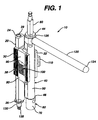
- a surgical milling and guide device 10 for use in preparing a proximal end of a femur to accept a femoral component of a hip prosthesis is shown.
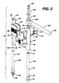
- the milling and guide device 10 includes a mounting member 20, a mounting frame 30, a guide member 40, a milling assembly 60, a connection frame 90, a connection mechanism 100, and a handle member 120.
- the mounting member 20 as illustrated in FIGS. 1-3, has a longitudinal axis 22, a proximal end 24 and a distal end 26.
- the mounting member 20 further includes a bore 28 extending at least partially into the distal end 26 of the mounting member 20.
- the bore 28 is shown to be of a circular shape, one of ordinary skill in the art will appreciate that it can be of any other suitable shape that allows a sufficient amount of pivoting or rotation of the mounting member 20, when the mounting member 20 is mounted to a mounting rod 130, as described below.
- the mounting member 20 includes a mounting frame 30 which extends from the mounting member 20 in a direction generally transverse to the longitudinal axis 22 of the mounting member 20.
- the mounting frame 30 has two protruding flange portions 32, each having a superior mating surface 34 and an inferior surface 36.
- the superior mating surface 34 has a plurality of detents 38 formed thereon which extend in a direction generally parallel to the longitudinal axis 22 of the mounting member 20.
- the detents 38 may extend across the entire length of the superior mating surface 34 or they may extend only partially across the superior mating surface 34.
- the detents 38 engage the connection mechanism 100 of the device 10 to provide for the incremental adjustment of the guide member 40 relative to the mounting member 20, as discussed below.
- the guide member 40 has a longitudinal axis 42, a proximal end 44 and a distal end 46.
- the guide member 40 includes a shaft portion 50 having a bore 52 extending therethrough, through which is mounted a milling assembly 60 for the milling of the proximal end of the femur.
- the milling assembly 60 is rotatably mounted within the bore 52 of the shaft 50. As shown in FIGS. 2, 3, 5 and 6, the milling assembly 60 further includes an end mill cutter 70 with cutting teeth 78 at a distal end thereof.
- the milling assembly 60 further includes an elongate shaft 72 which extends proximally from the end mill cutter 70 and has a proximal end 74 and a distal end 76.
- the elongate shaft 72 is rotatably mountable within the bore 52 of the guide member 40.
- a proximal end 74 of the elongate shaft 72 is attachable to a connector element 80.
- the connector element 80 of the milling assembly 60 is a Hudson end separately attachable at a first end 82 to a drill (not shown) and at a second end 84 to the proximal end 74 of the elongate shaft 72.
- End mill cutters suitable for use in a surgical environment to mill or plane a bone can be used with the system of the invention.
- the end mill cutter 70 has the following characteristics: 8 cutting teeth, 10° RH Helix/RH Cut, cylindrical land with end cutting teeth, 7° primary, 15° secondary, and 2 center cutting flutes.
- the guide member 40 further includes a connection frame 90 which extends in a direction generally transverse to the longitudinal axis 42 of the guide member 40.
- the connection frame 90 may be formed of spaced elements positioned on opposing sides of the guide member shaft portion 50 that receive the extending flange portions 32 of the mounting frame 30.
- the connection frame 90 further includes connection mechanism 100 which secures the guide member 40 to the mounting member 20.
- the connection mechanism 100 also enables the incremental adjustment of the guide member 40 relative to the mounting member 20 such that the longitudinal axis 22 of the mounting member 20 and the longitudinal axis 42 of the guide member 40 are spaced apart by a desired distance "d", as shown in FIG. 3.
- the distance "d" can be adjusted as needed, within the range of about 2.5 cm to 5 cm.
- the connection mechanism 100 further includes at least one pawl member 110 mounted on the connection frame 90 on the guide member 40.
- connection mechanism also includes a pawl member 110 that engages and interlocks with the detents 38 of the mounting frame 30.
- pawls 110 are positioned on either side of the connection frame 90.
- Each pawl member 110 has a tab portion 111, a superior surface 114 and an inferior engaging surface 116.
- the inferior engaging surface 116 has a plurality of pawl teeth 112 which are adapted to engage and interlock with the detents 38 formed on the mounting frame 30.
- the at least one pawl member 110 secures the guide member 40 to the mounting member 20 while allowing for the selective incremental adjustment of the distance (d) between the longitudinal axis 22 of the mounting member 20 and the longitudinal axis 42 of the guide member 40.
- the pawl member 110 may be secured to the connection frame 90 of the guide member 40 by a securing pin 119.
- the connection mechanism 100 further includes a spring 118 disposed within a recess 117 formed beneath the pawl tab portion 111 and biased against the connection frame 90 to facilitate adjustment of the guide member 40 relative to the mounting member 20.
- the spring 118 when in an extended position between the at least one pawl member 110 and the connection frame 90, biases the pawl 110 to a position in which the pawl teeth 112 engage detents 38 of mounting frame 30, thereby preventing unintentional disengagement of the pawl teeth 112 from the detents 38.
- Incremental adjustment of the device 10 may be made by grasping and depressing the pawl tab 111 to remove the engagement between detents 38 and pawl teeth 112.
- the guide member 40 may be moved in a direction generally transverse to the longitudinal axis 22 of the mounting member 20. Releasing the pawl tab 111 re-engages the pawl teeth 112 to the detents 38 and secures the guide member 40 to the mounting member 20 in the desired position.
- the system further includes a handle member 120 which extends in a direction generally transverse to the longitudinal axis 42 of the guide member 40.
- the handle 120 allows a surgeon to grasp and manipulate the system from a variety of positions depending on factors such as the location of the incision made on a patient.
- the handle 120 has a longitudinal axis 122, a proximal end 124 and a distal end 126.
- the distal end 126 of the handle 120 includes a hexagonally shaped coupling 128 which is attachable to a complementarily shaped proximal end 44 of guide member 40.
- the handle 120 may also be used to rotate or pivot the milling assembly 60 to provide a radial cutting path when the system is mounted on a mounting rod 130.
- the system also includes a mounting rod 130, having a proximal end 134 and a distal end 136.
- the mounting rod 130 further includes a threaded portion 138 proximate the distal end 136.
- the threaded portion 138 is matable with a trial component such as a proximal portion of a hip stem trial component 150, as shown in FIG. 7.
- the milling guide and system as described herein may be further assembled as follows. First, the mounting rod 130 is screwed onto a proximal portion 150 of a trial femoral implant for a hip prosthesis. The handle 120, in its desired orientation, is then fitted onto the proximal end 44 of the guide member 40. Next, the milling assembly 60 is inserted into the bore 52 of the guide member shaft 52 and secured proximate the proximal end 44 of the guide member 40 by connector element 80. The guide member 40 is then joined to the mounting member 20 by interlocking engagement of the connection mechanism 100 on the guide member 40 to the mounting frame 30 on the mounting member 20, as described above.
- the mounting member 20, to which is attached the guide member 40 is positioned on the mounting rod 130.
- the distal end 26 of the mounting member 20 and the bottom portion 75 of the end mill cutter 70 are substantially flush with one another on a calcar plane 170, as shown in FIGS. 3 and 7.
- the calcar region 144 of the proximal femur 142 is now ready to be milled using the system 10.
- the milling system of the invention enables the adjustment of the distance (d) between axes 22, 42.
- the position of the guide member 70 is adjustable relative to the position of the mounting member 20 to thereby effect a corresponding variation in the position of the end mill cutter 70.
- the guide member 70 is adjustable in the medial/lateral direction, as designated by arrow 166 in the range of about 2.5 cm to 5 cm.
- the surgeon can move the end mill cutter 70 in the radial cutting path, as illustrated by arrows 160 and 162, with respect to the center axis 164 of the mounting rod 130. Varying the distance (d) between the guide member 40 and the mounting member 20, effectively decreases the effective radial cutting path of the end mill cutter 70.
- the surgical device as described herein may be made from a variety of biocompatible materials, such as stainless steel, titanium, anodized aluminum or other similar metals and metal alloys.
- the surgical device and system of the present invention may be employed in a variety of surgical applications, particularly those related to hip prostheses, and more particularly to the attachment of a femoral component of a hip prosthesis.
- An exemplary procedure for using the surgical system of the present invention begins with the step of removing a portion of a proximal end of a femur.
- a trial femoral stem component 150 and stem body 152 as illustrated in FIG. 7 are then positioned within the proximal end of the femur.
- the calcar region 144 of the proximal femur 142 is then milled flush to the proximal sleeve 150 using the system as described herein. Milling can be performed in a plunge cut fashion or in a substantially side cutting motion.
Landscapes
- Health & Medical Sciences (AREA)
- Surgery (AREA)
- Life Sciences & Earth Sciences (AREA)
- Biomedical Technology (AREA)
- Medical Informatics (AREA)
- Orthopedic Medicine & Surgery (AREA)
- Oral & Maxillofacial Surgery (AREA)
- Engineering & Computer Science (AREA)
- Dentistry (AREA)
- Heart & Thoracic Surgery (AREA)
- Nuclear Medicine, Radiotherapy & Molecular Imaging (AREA)
- Molecular Biology (AREA)
- Animal Behavior & Ethology (AREA)
- General Health & Medical Sciences (AREA)
- Public Health (AREA)
- Veterinary Medicine (AREA)
- Prostheses (AREA)
- Surgical Instruments (AREA)
Applications Claiming Priority (2)
| Application Number | Priority Date | Filing Date | Title |
|---|---|---|---|
| US09/088,400 US5976145A (en) | 1998-06-01 | 1998-06-01 | Calcar milling guide and system |
| US88400 | 1998-06-01 |
Publications (2)
| Publication Number | Publication Date |
|---|---|
| EP0962190A2 true EP0962190A2 (de) | 1999-12-08 |
| EP0962190A3 EP0962190A3 (de) | 2000-07-05 |
Family
ID=22211158
Family Applications (1)
| Application Number | Title | Priority Date | Filing Date |
|---|---|---|---|
| EP99304205A Withdrawn EP0962190A3 (de) | 1998-06-01 | 1999-05-28 | Führung und System zum Fräsen des Femurcalcars |
Country Status (3)
| Country | Link |
|---|---|
| US (1) | US5976145A (de) |
| EP (1) | EP0962190A3 (de) |
| JP (1) | JP2000000243A (de) |
Cited By (6)
| Publication number | Priority date | Publication date | Assignee | Title |
|---|---|---|---|---|
| EP1374779A3 (de) * | 2002-06-21 | 2005-03-30 | DePuy Products, Inc. | Schneidlehre und Schneidevorrichtung zum Entfernen einer Prothese |
| US7081119B2 (en) | 2003-08-01 | 2006-07-25 | Hfsc Company | Drill guide assembly for a bone fixation device |
| US7357804B2 (en) | 2003-08-13 | 2008-04-15 | Synthes (U.S.A.) | Quick-release drill-guide assembly for bone-plate |
| US7507242B2 (en) | 2004-06-02 | 2009-03-24 | Facet Solutions | Surgical measurement and resection framework |
| US8491596B2 (en) | 2002-06-21 | 2013-07-23 | Depuy Products, Inc. | Method for removal of bone |
| WO2019159061A3 (en) * | 2018-02-15 | 2019-10-17 | DePuy Synthes Products, Inc. | Orthopaedic surgical instrument system for preparing a patient's calcar |
Families Citing this family (48)
| Publication number | Priority date | Publication date | Assignee | Title |
|---|---|---|---|---|
| US6725080B2 (en) * | 2000-03-01 | 2004-04-20 | Surgical Navigation Technologies, Inc. | Multiple cannula image guided tool for image guided procedures |
| KR100421426B1 (ko) * | 2001-04-19 | 2004-03-09 | 한국과학기술원 | 고관절 전치환 수술을 위한 장착형 수술로봇 |
| US6916323B2 (en) * | 2001-08-21 | 2005-07-12 | Depuy Products, Inc. | Method and apparatus for percutaneously securing a bone screw and a bone plate to a bone of a patient |
| US7090677B2 (en) * | 2002-02-12 | 2006-08-15 | Medicine Lodge, Inc. | Surgical milling instrument for shaping a bone cavity |
| US8998919B2 (en) | 2003-06-25 | 2015-04-07 | DePuy Synthes Products, LLC | Assembly tool for modular implants, kit and associated method |
| US7297166B2 (en) | 2003-06-25 | 2007-11-20 | Depuy Products, Inc. | Assembly tool for modular implants and associated method |
| US7074224B2 (en) | 2003-06-25 | 2006-07-11 | Depuy Products, Inc. | Modular tapered reamer for bone preparation and associated method |
| US7582092B2 (en) | 2003-06-25 | 2009-09-01 | Depuy Products, Inc. | Assembly tool for modular implants and associated method |
| US7731721B2 (en) * | 2003-07-16 | 2010-06-08 | Synthes Usa, Llc | Plating system with multiple function drill guide |
| US7481814B1 (en) | 2003-07-28 | 2009-01-27 | Biomet Manufacturing Corporation | Method and apparatus for use of a mill or reamer |
| US7909860B2 (en) | 2003-09-03 | 2011-03-22 | Synthes Usa, Llc | Bone plate with captive clips |
| US20050049595A1 (en) | 2003-09-03 | 2005-03-03 | Suh Sean S. | Track-plate carriage system |
| US7785328B2 (en) | 2003-12-30 | 2010-08-31 | Depuy Products, Inc. | Minimally invasive bone miller apparatus |
| US7033361B2 (en) * | 2004-02-19 | 2006-04-25 | Howmedica Osteonics Corp. | Tibial cutting guide having variable adjustment |
| US7608079B1 (en) | 2004-03-05 | 2009-10-27 | Biomet Manufacturing Corp. | Unicondylar knee apparatus and system |
| US7488327B2 (en) | 2004-04-12 | 2009-02-10 | Synthes (U.S.A.) | Free hand drill guide |
| US7641698B1 (en) | 2004-06-04 | 2010-01-05 | Biomet Manufacturing Corp. | Modular hip joint implant |
| US7179259B1 (en) | 2004-06-04 | 2007-02-20 | Biomet Manufacturing Corp. | Instrument assembly for lateral implant |
| US7927335B2 (en) | 2004-09-27 | 2011-04-19 | Depuy Products, Inc. | Instrument for preparing an implant support surface and associated method |
| US7892287B2 (en) | 2004-09-27 | 2011-02-22 | Depuy Products, Inc. | Glenoid augment and associated method |
| US7922769B2 (en) | 2004-09-27 | 2011-04-12 | Depuy Products, Inc. | Modular glenoid prosthesis and associated method |
| US20060100634A1 (en) * | 2004-11-09 | 2006-05-11 | Sdgi Holdings, Inc. | Technique and instrumentation for measuring and preparing a vertebral body for device implantation using datum block |
| GB0426385D0 (en) * | 2004-12-01 | 2005-01-05 | Benoist Girard Sas | Prosthetic implanatation inserter for a flexible acetabular cup |
| US7670343B2 (en) * | 2006-06-14 | 2010-03-02 | Biomet Manufacturing Corp. | Method and apparatus for reaming an acetabulum |
| US7805853B2 (en) * | 2006-08-31 | 2010-10-05 | David H Littig | Transfemoral pelvic impression system |
| US8052687B2 (en) * | 2006-09-29 | 2011-11-08 | Depuy Products, Inc. | Calcar planar |
| US8597298B2 (en) | 2006-09-29 | 2013-12-03 | DePuy Synthes Products, LLC | Proximal reamer |
| US8556912B2 (en) | 2007-10-30 | 2013-10-15 | DePuy Synthes Products, LLC | Taper disengagement tool |
| US8518050B2 (en) | 2007-10-31 | 2013-08-27 | DePuy Synthes Products, LLC | Modular taper assembly device |
| US8167882B2 (en) | 2008-09-30 | 2012-05-01 | Depuy Products, Inc. | Minimally invasive bone miller apparatus |
| US8241365B2 (en) * | 2008-12-23 | 2012-08-14 | Depuy Products, Inc. | Shoulder prosthesis with vault-filling structure having bone-sparing configuration |
| US8231683B2 (en) | 2009-12-08 | 2012-07-31 | Depuy Products, Inc. | Shoulder prosthesis assembly having glenoid rim replacement structure |
| US8419743B2 (en) | 2010-03-05 | 2013-04-16 | Biomet Manufacturing Corp. | Assembly tool for modular implants and associated method |
| US8529569B2 (en) | 2010-03-05 | 2013-09-10 | Biomet Manufacturing, Llc | Method and apparatus for preparing a proximal femur |
| US8333807B2 (en) * | 2010-03-05 | 2012-12-18 | Biomet Manufacturing Corp. | Method and apparatus for trialing and implanting a modular femoral hip |
| US8221432B2 (en) | 2010-03-05 | 2012-07-17 | Biomet Manufacturing Corp. | Method and apparatus for implanting a modular femoral hip |
| US8679130B2 (en) * | 2010-03-05 | 2014-03-25 | Biomet Manufacturing, Llc | Guide assembly for lateral implants and associated methods |
| US8460393B2 (en) * | 2010-03-05 | 2013-06-11 | Biomet Manufacturing Corp. | Modular lateral hip augments |
| US8533921B2 (en) | 2010-06-15 | 2013-09-17 | DePuy Synthes Products, LLC | Spiral assembly tool |
| US9095452B2 (en) | 2010-09-01 | 2015-08-04 | DePuy Synthes Products, Inc. | Disassembly tool |
| US8465548B2 (en) | 2010-11-24 | 2013-06-18 | DePuy Synthes Products, LLC | Modular glenoid prosthesis |
| US8480750B2 (en) | 2010-11-24 | 2013-07-09 | DePuy Synthes Products, LLC | Modular glenoid prosthesis |
| CN103813764B (zh) | 2011-04-06 | 2017-04-19 | 德普伊新特斯产品有限责任公司 | 植入修正髋关节假体的器械组件和使用它的整形外科手术 |
| WO2013086340A1 (en) | 2011-12-09 | 2013-06-13 | Howmedica Osteonics Corp. | Surgical reaming instrument for shaping a bone cavity |
| AU2012362279A1 (en) | 2011-12-30 | 2014-07-24 | Howmedica Osteonics Corp. | Systems for preparing bone voids to receive a prosthesis |
| US9526513B2 (en) | 2013-03-13 | 2016-12-27 | Howmedica Osteonics Corp. | Void filling joint prosthesis and associated instruments |
| US10149763B2 (en) | 2015-01-12 | 2018-12-11 | Howmedica Osteonics Corp. | Multipurpose void filling prosthesis |
| US10327789B2 (en) * | 2015-12-29 | 2019-06-25 | Medos International Sarl | Methods and systems for preparing bone for a surgical procedure |
Family Cites Families (12)
| Publication number | Priority date | Publication date | Assignee | Title |
|---|---|---|---|---|
| CH670198A5 (de) * | 1986-10-02 | 1989-05-31 | Sulzer Ag | |
| GB9101598D0 (en) * | 1991-01-24 | 1991-03-06 | Aesculap Ltd | Bone removal means |
| US5133766A (en) * | 1991-03-04 | 1992-07-28 | Halpern Alan A | Femoral head remodeling and femoral insert and drilling aid therefor |
| US5417695A (en) * | 1992-07-27 | 1995-05-23 | Pfizer Hospital Products Group, Inc. | Instrumentation for preparing a distal femur |
| EP0673231B1 (de) * | 1992-11-20 | 2002-02-13 | BURKE, Dennis, W. | Verbessertes femorales manschettenimplantat |
| US5403320A (en) * | 1993-01-07 | 1995-04-04 | Venus Corporation | Bone milling guide apparatus and method |
| US5540694A (en) * | 1993-06-01 | 1996-07-30 | Joint Medical Products Corporation | Instrument for cutting bone |
| US5468243A (en) * | 1993-10-27 | 1995-11-21 | Halpern; Alan A. | Femoral superior neck remodelling means and method |
| US5643271A (en) * | 1994-09-09 | 1997-07-01 | Sulzer Orthopedics Inc. | Angled orthopedic surfacer and guide |
| DE19510372C1 (de) * | 1995-03-22 | 1996-07-25 | Aesculap Ag | Bohrlehre für chirurgische Bohrwerkzeuge |
| US5688283A (en) * | 1995-11-17 | 1997-11-18 | Knapp; John G. | Drill guide for mandibular staple transosseous implants |
| US6152963A (en) * | 1996-01-04 | 2000-11-28 | Joint Medical Products Corporation | Method and apparatus for fitting a prosthesis to a bone |
-
1998
- 1998-06-01 US US09/088,400 patent/US5976145A/en not_active Expired - Fee Related
-
1999
- 1999-05-28 EP EP99304205A patent/EP0962190A3/de not_active Withdrawn
- 1999-06-01 JP JP11154379A patent/JP2000000243A/ja active Pending
Non-Patent Citations (1)
| Title |
|---|
| None |
Cited By (11)
| Publication number | Priority date | Publication date | Assignee | Title |
|---|---|---|---|---|
| EP1374779A3 (de) * | 2002-06-21 | 2005-03-30 | DePuy Products, Inc. | Schneidlehre und Schneidevorrichtung zum Entfernen einer Prothese |
| AU2003204784B2 (en) * | 2002-06-21 | 2009-04-23 | Depuy Products, Inc. | Prosthesis removal cutting guide, cutting tool and method |
| AU2009202497B2 (en) * | 2002-06-21 | 2010-08-26 | Depuy Products, Inc. | Prosthesis removal cutting guide, cutting tool and method |
| US7935118B2 (en) | 2002-06-21 | 2011-05-03 | Depuy Products, Inc. | Prosthesis removal cutting guide, cutting tool and method |
| US8491596B2 (en) | 2002-06-21 | 2013-07-23 | Depuy Products, Inc. | Method for removal of bone |
| US8545507B2 (en) | 2002-06-21 | 2013-10-01 | DePuy Synthes Products, LLC | Prosthesis removal cutting guide, cutting tool and method |
| US7081119B2 (en) | 2003-08-01 | 2006-07-25 | Hfsc Company | Drill guide assembly for a bone fixation device |
| US7357804B2 (en) | 2003-08-13 | 2008-04-15 | Synthes (U.S.A.) | Quick-release drill-guide assembly for bone-plate |
| US7507242B2 (en) | 2004-06-02 | 2009-03-24 | Facet Solutions | Surgical measurement and resection framework |
| US7588578B2 (en) | 2004-06-02 | 2009-09-15 | Facet Solutions, Inc | Surgical measurement systems and methods |
| WO2019159061A3 (en) * | 2018-02-15 | 2019-10-17 | DePuy Synthes Products, Inc. | Orthopaedic surgical instrument system for preparing a patient's calcar |
Also Published As
| Publication number | Publication date |
|---|---|
| EP0962190A3 (de) | 2000-07-05 |
| US5976145A (en) | 1999-11-02 |
| JP2000000243A (ja) | 2000-01-07 |
Similar Documents
| Publication | Publication Date | Title |
|---|---|---|
| US5976145A (en) | Calcar milling guide and system | |
| US5514136A (en) | Surgical instrument for driving and rotating a long bone prosthesis | |
| JP4018222B2 (ja) | 整形外科手術用医療器具 | |
| US7104995B2 (en) | Method of preparing an acetabulum for receiving a head of a femoral prosthesis | |
| JP4237044B2 (ja) | モジュール式移植片のための整合装置 | |
| EP0931513B1 (de) | Reibsystem für längliche Hüftgelenkpfanne | |
| US7264589B2 (en) | Method for humerus retraction | |
| US6702824B2 (en) | Prosthesis positioning apparatus | |
| US5957925A (en) | Orthopaedic milling instrument | |
| EP1491149A1 (de) | Gelenkfräsvorrichtung | |
| US20080255565A1 (en) | Broach handle for minimally invasive hip replacement surgery | |
| US20110276100A1 (en) | Alignment guide | |
| EP0959790A1 (de) | Anordnung zum ausrichten und führen von inzisionen an der elle | |
| US11376055B2 (en) | System and method for attaching a surgical instrument to a patient's bone | |
| US11413161B2 (en) | System and method for total hip arthroplasty | |
| EP2422717B1 (de) | Instrument zur Führung der Resektion eines grossen Tuberkels | |
| US10271963B2 (en) | Referencing apparatus and associated methods | |
| US20190282376A1 (en) | Instrument assembly for use in hip replacement surgery | |
| WO2014147529A1 (en) | Set of instruments for the implantation of an acetabular prosthesis |
Legal Events
| Date | Code | Title | Description |
|---|---|---|---|
| PUAI | Public reference made under article 153(3) epc to a published international application that has entered the european phase |
Free format text: ORIGINAL CODE: 0009012 |
|
| AK | Designated contracting states |
Kind code of ref document: A2 Designated state(s): DE FR GB IE IT |
|
| AX | Request for extension of the european patent |
Free format text: AL;LT;LV;MK;RO;SI |
|
| PUAL | Search report despatched |
Free format text: ORIGINAL CODE: 0009013 |
|
| RIC1 | Information provided on ipc code assigned before grant |
Free format text: 7A 61B 17/17 A, 7A 61B 17/16 B |
|
| AK | Designated contracting states |
Kind code of ref document: A3 Designated state(s): AT BE CH CY DE DK ES FI FR GB GR IE IT LI LU MC NL PT SE |
|
| AX | Request for extension of the european patent |
Free format text: AL;LT;LV;MK;RO;SI |
|
| 17P | Request for examination filed |
Effective date: 20001212 |
|
| AKX | Designation fees paid |
Free format text: DE FR GB IE IT |
|
| RAP1 | Party data changed (applicant data changed or rights of an application transferred) |
Owner name: DEPUY PRODUCTS, INC. |
|
| RAP1 | Party data changed (applicant data changed or rights of an application transferred) |
Owner name: DEPUY PRODUCTS, INC. |
|
| 17Q | First examination report despatched |
Effective date: 20040603 |
|
| STAA | Information on the status of an ep patent application or granted ep patent |
Free format text: STATUS: THE APPLICATION IS DEEMED TO BE WITHDRAWN |
|
| 18D | Application deemed to be withdrawn |
Effective date: 20041214 |