EP0962052B1 - Temperature insensitive silicon oscillator and precision voltage reference formed therefrom - Google Patents
Temperature insensitive silicon oscillator and precision voltage reference formed therefrom Download PDFInfo
- Publication number
- EP0962052B1 EP0962052B1 EP98910052A EP98910052A EP0962052B1 EP 0962052 B1 EP0962052 B1 EP 0962052B1 EP 98910052 A EP98910052 A EP 98910052A EP 98910052 A EP98910052 A EP 98910052A EP 0962052 B1 EP0962052 B1 EP 0962052B1
- Authority
- EP
- European Patent Office
- Prior art keywords
- frequency
- substrate
- finger electrodes
- sense
- axis
- Prior art date
- Legal status (The legal status is an assumption and is not a legal conclusion. Google has not performed a legal analysis and makes no representation as to the accuracy of the status listed.)
- Expired - Lifetime
Links
Images


Classifications
-
- G—PHYSICS
- G01—MEASURING; TESTING
- G01C—MEASURING DISTANCES, LEVELS OR BEARINGS; SURVEYING; NAVIGATION; GYROSCOPIC INSTRUMENTS; PHOTOGRAMMETRY OR VIDEOGRAMMETRY
- G01C19/00—Gyroscopes; Turn-sensitive devices using vibrating masses; Turn-sensitive devices without moving masses; Measuring angular rate using gyroscopic effects
- G01C19/56—Turn-sensitive devices using vibrating masses, e.g. vibratory angular rate sensors based on Coriolis forces
- G01C19/5719—Turn-sensitive devices using vibrating masses, e.g. vibratory angular rate sensors based on Coriolis forces using planar vibrating masses driven in a translation vibration along an axis
- G01C19/5733—Structural details or topology
- G01C19/574—Structural details or topology the devices having two sensing masses in anti-phase motion
-
- H—ELECTRICITY
- H03—ELECTRONIC CIRCUITRY
- H03H—IMPEDANCE NETWORKS, e.g. RESONANT CIRCUITS; RESONATORS
- H03H9/00—Networks comprising electromechanical or electro-acoustic elements; Electromechanical resonators
- H03H9/02—Details
- H03H9/02244—Details of microelectro-mechanical resonators
- H03H9/02433—Means for compensation or elimination of undesired effects
- H03H9/02448—Means for compensation or elimination of undesired effects of temperature influence
-
- H—ELECTRICITY
- H03—ELECTRONIC CIRCUITRY
- H03H—IMPEDANCE NETWORKS, e.g. RESONANT CIRCUITS; RESONATORS
- H03H9/00—Networks comprising electromechanical or electro-acoustic elements; Electromechanical resonators
- H03H9/24—Constructional features of resonators of material which is not piezoelectric, electrostrictive, or magnetostrictive
- H03H9/2405—Constructional features of resonators of material which is not piezoelectric, electrostrictive, or magnetostrictive of microelectro-mechanical resonators
-
- H—ELECTRICITY
- H03—ELECTRONIC CIRCUITRY
- H03H—IMPEDANCE NETWORKS, e.g. RESONANT CIRCUITS; RESONATORS
- H03H9/00—Networks comprising electromechanical or electro-acoustic elements; Electromechanical resonators
- H03H9/24—Constructional features of resonators of material which is not piezoelectric, electrostrictive, or magnetostrictive
- H03H9/2405—Constructional features of resonators of material which is not piezoelectric, electrostrictive, or magnetostrictive of microelectro-mechanical resonators
- H03H9/2426—Constructional features of resonators of material which is not piezoelectric, electrostrictive, or magnetostrictive of microelectro-mechanical resonators in combination with other electronic elements
-
- H—ELECTRICITY
- H03—ELECTRONIC CIRCUITRY
- H03L—AUTOMATIC CONTROL, STARTING, SYNCHRONISATION OR STABILISATION OF GENERATORS OF ELECTRONIC OSCILLATIONS OR PULSES
- H03L1/00—Stabilisation of generator output against variations of physical values, e.g. power supply
- H03L1/02—Stabilisation of generator output against variations of physical values, e.g. power supply against variations of temperature only
-
- H—ELECTRICITY
- H03—ELECTRONIC CIRCUITRY
- H03L—AUTOMATIC CONTROL, STARTING, SYNCHRONISATION OR STABILISATION OF GENERATORS OF ELECTRONIC OSCILLATIONS OR PULSES
- H03L7/00—Automatic control of frequency or phase; Synchronisation
- H03L7/06—Automatic control of frequency or phase; Synchronisation using a reference signal applied to a frequency- or phase-locked loop
- H03L7/08—Details of the phase-locked loop
- H03L7/099—Details of the phase-locked loop concerning mainly the controlled oscillator of the loop
-
- H—ELECTRICITY
- H03—ELECTRONIC CIRCUITRY
- H03H—IMPEDANCE NETWORKS, e.g. RESONANT CIRCUITS; RESONATORS
- H03H9/00—Networks comprising electromechanical or electro-acoustic elements; Electromechanical resonators
- H03H9/02—Details
- H03H9/02244—Details of microelectro-mechanical resonators
- H03H2009/02488—Vibration modes
- H03H2009/02496—Horizontal, i.e. parallel to the substrate plane
-
- H—ELECTRICITY
- H03—ELECTRONIC CIRCUITRY
- H03H—IMPEDANCE NETWORKS, e.g. RESONANT CIRCUITS; RESONATORS
- H03H9/00—Networks comprising electromechanical or electro-acoustic elements; Electromechanical resonators
- H03H9/02—Details
- H03H9/02244—Details of microelectro-mechanical resonators
- H03H2009/02488—Vibration modes
- H03H2009/02511—Vertical, i.e. perpendicular to the substrate plane
Definitions
- the present invention relates to frequency and voltage references, and in particular to temperature insensitive oscillators and radiation-hard precision voltage references formed from a micromechanical gyroscope.
- Tuning forks used for time keeping in watches, clocks, and computers are presently made of quartz.
- quartz oscillators are sufficiently accurate for most typical applications and are relatively inexpensive to fabricate.
- quartz flexures oriented properly with respect to crystallographic axes have a resonant frequency linear thermal variation of zero and a second order frequency sensitivity of -0.035 ppm/°C 2 .
- quartz oscillators are typically too large (3 to 5 mm in length, formed from one inch wafers) for micromechanical implementations. Such larger devices increase system expense in some applications by requiring more area on a substrate, and are themselves more expensive to fabricate than silicon devices.
- PVRs radiation hard precision voltage references
- none of the currently available PVRs are radiation hard, but rather exhibit large PVR shifts under radiation.
- PVRs based on compensated avalanche diodes, tunnel diodes, nuclear magnetic resonance spectroscopy, and electron spin resonance have failed to satisfy requirements for radiation hardness in strategic missile guidance systems.
- PVRs are of greater bulk than ideally desired, and require special doping profiles, leading to increased cost.
- mechanical resonant frequencies are not subject to shifts under radiation.
- Exemplary oscillators in the prior art include U.S. Patent Number 3,736,740 to Pindell and U.S. Patent Number 5,025,346 to Tang , et.al.
- the Pindell patent discloses a timing mechanism that includes a rotary oscillatory member that is biased towards a neutral position. The member is electromagnetically pulsed in one direction so that it oscillates at a predetermined natural frequency.
- the Tang patent discloses a resonant microstructure and movable plate that are disposed over and parallel to a substrate.
- the microstructure includes a stationary, thin film electrode that has at least one comb with fingers.
- the movable plate also includes at least one comb with fingers that are "interdigitated" with the fingers of the electrode.
- the present invention provides a frequency or voltage reference device according to claim 1.
- Micromachined, thermally insensitive silicon resonators are provided having accuracy equivalent or superior to that of currently employed, thermally varying quartz resonators.
- a micromechanical device based upon a tuning fork gyroscope such as that disclosed in commonly assigned U.S. Patent No. 5,349,855
- resonators are made from either or both of the gyro drive and sense axes. Further, such resonators are employed in the creation of radiation-hard precision voltage references (PVRs).
- PVRs radiation-hard precision voltage references
- a tuning fork gyroscope constructed on a glass substrate and having proper flexure design provides a thermal sensitivity in the silicon oscillators approximately two orders of magnitude below that of a silicon oscillator fabricated according to silicon-on-silicon processes. This reduced thermal sensitivity is comparable to that of a quartz oscillator.
- Silicon tuning forks (0.3 to 2 mm) are smaller than quartz tuning forks (3 to 5 mm), and thus are less expensive to incorporate into a densely packed circuit or small device. Further, a greater number of organizations are fabricating silicon versus quartz, so that temperature insensitive oscillators and radiation hard PVRs could be more widely available. Such availability results in a lower cost for silicon devices compared to comparable quartz devices.
- the tuning fork gyroscope provides two second order systems, each of which can be used as a resonator.
- a gyroscope proof mass is driven and sensed along a Y axis orthogonal to the plane of the glass substrate.
- comb drive and sense capabilities are utilized along a plane parallel to the glass substrate.
- a first PVR is fashioned from the first, Y axis resonator.
- the resonant frequency of the temperature insensitive silicon resonator varies with the voltage bias.
- the bias voltage adjusted to maintain the resonant frequency, becomes the reference voltage.
- a second PVR is fashioned from the second, X axis resonator.
- suspension beam stiffness becomes non-linear at larger excitation amplitudes along the X axis. Damping and ambient pressure must be tightly controlled to prevent the varying of the drive amplitude and resonant frequency.
- the first PVR is preferred.
- the present invention contemplates a micromachined, thermally insensitive silicon resonator of silicon-on-glass fabrication having accuracy equivalent or superior to that of currently employed, thermally varying quartz resonators.
- a resonator is realized using a micromechanical, silicon-on-glass tuning fork gyroscope.
- a first thermally insensitive reference oscillator 5 is implemented by providing a reference voltage from an oscillator loop 8 to at least one sense or drive axis force electrode 2 of a micromechanical silicon tuning fork gyroscope (TFG) 4 fabricated on a glass substrate.
- the force electrode 2 imparts motive force on a vibratory mass referred to above as a proof mass 1, wherein the proof mass 1 vibrates at a resonant frequency.
- At least one sense electrode 3 disposed proximate the proof mass 1 detects this oscillation, and returns a signal, modulated at the resonant frequency, to the oscillator loop 8 at a reference frequency f REF .
- the sense electrode 3 is connected to the drive electrode 2 through the oscillator loop 8.
- the mechanical frequency of oscillation and electrical output f REF are identical.
- FIG. 1 Other embodiments of the illustrated reference oscillator are fabricated from silicon-on-glass devices other than the aforementioned comb-drive tuning fork gyroscope.
- the present invention further contemplates a radiation-hard precision voltage reference (PVR) which is fabricated from a micromachined, thermally insensitive silicon resonator of silicon-on-glass fabrication, such as that shown schematically in Fig. 1 . Because mechanical resonant frequencies are not changed by radiation, the PVR is radiation hard.
- PVR radiation-hard precision voltage reference
- a micromechanical, silicon-on-glass tuning fork gyroscope is employed in the realization of a first embodiment of the PVR, though other silicon-on-glass configurations are employable in alternative embodiments.
- a precision voltage reference (PVR) 11 is fabricated from the silicon-on-glass, micromechanical tuning fork gyroscope (TFG) 4.
- TFG micromechanical tuning fork gyroscope
- a proof mass 1 is excited into resonant motion by way of at least one energized force electrode 2 along either the sense or drive axes.
- An oscillator loop 8 provides the AC excitation energy in this first embodiment.
- a frequency control loop 21 compares a reference frequency f REF from a frequency standard 23 to a sensed proof mass oscillation frequency from the oscillator loop 8, and a DC correction signal is applied to the proof mass 1.
- the detected frequency of oscillation is synchronized with a reference frequency by adjusting an applied DC bias, which is then available as a reference voltage V REF.
- the gyroscope employed in such realizations is a tuning fork gyroscope in which drive and driven electrode pairs, responsible for imparting vibrational motion to the tuning fork vibrating elements, are formed by plural respective interleaved fingers which greatly increase the area and capacitance as well as capacitance change with motion of the device so as to substantially enhance the system sensitivity.
- drive and driven electrode pairs responsible for imparting vibrational motion to the tuning fork vibrating elements
- Such a drive structure is consistent with fabrication techniques that allow for a greater mass to the vibrating element which cooperates with the higher efficiency drive in providing an increased sensitivity.
- the tuning fork structure has a high mechanical quality factor (Q), due to the opposing motion which tends to reduce the stress reaching the support points and hence reduce the coupling of energy out of the structure.
- the frequency stability of silicon flexures in a micromechanical device is significantly effected by the thermal sensitivity of Young's modulus.
- frequency stability on the order of -10ppm/°C is typical.
- a clock employing such an oscillator to be accurate to ten seconds per month requires frequency accuracy of 4 ppm over thermal variation, a figure routinely achieved by quartz tuning forks.
- the thermal sensitivity of silicon oscillators is reduced two orders of magnitude to a performance level comparable with that of quartz.
- a tuning fork rate sensitive structure 10 suitable for use in the realization of a thermally insensitive oscillator and a radiation hard, precision voltage reference (PVR) according to the present invention are illustrated in Figs. 3, 4 and 5 .
- PVR radiation hard, precision voltage reference
- the gyroscope 10 comprises the following functional elements, illustrated with respect to Figs. 3, 4 and 5 .
- Two proof masses 12 are each suspended above a glass substrate 14, and provide motion along two axes, X and Y.
- sense 16 and force 18 electrodes are disposed on the glass substrate 14, substantially beneath respective proof masses 12, for imparting and detecting proof mass 12 motion along the Y axis.
- the sense electrodes 16 provide information to sense electronics 17.
- the force electrodes 18, alternatively referred to as drive electrodes are driven by drive electronics 19.
- the sense and drive electronics comprise the oscillator loop 8 illustrated in Figs. 1 and 2 .
- the sense electronics 17 output is analyzed within the frequency control loop 21 with respect to the frequency standard 23 output in order to generate a DC bias. This bias is applied to the proof mass 12 and serves as the reference voltage output (V REF ).
- each proof mass 12 is provided with a plurality of proof mass fingers 20a, 20b extending along the X axis.
- These proof mass fingers 20a, 20b are arranged as outer proof mass fingers 20a and inner proof mass fingers 20b.
- Interspersed between the outer proof mass fingers 20a are outer fixed comb fingers 22a extending from outer fixed combs 24.
- Interspersed between the inner proof mass fingers 20b are inner fixed comb fingers 22b extending from inner fixed combs 26.
- the outer fixed combs 24 are connected to the drive electronics 19 of the oscillator loop 8 and act as drive sources, so that the outer fixed comb fingers 22a act as drive electrodes.
- the capacitive effect between the outer fixed comb fingers 22a and the outer proof mass fingers 20a results in proof mass motion along the X axis.
- This motion is detected by using the inner fixed combs 26 as sense devices and the inner fixed comb fingers 22b as sense electrodes, connected to the sense electronics 17.
- Capacitive variation sensed by the inner fixed comb fingers 22b provides an indication of proof mass 12 X axis motion.
- the interleaved fingers 20a, 20b, 22a, 22b provide increased surface area for creation of capacitance and detection of capacitive change with motion of the device, substantially increasing the sensitivity of the device.
- the sensed frequency from the sense electronics 17 is analyzed in the frequency control loop 21 with respect to the frequency standard 23 to generate the reference voltage.
- Alternative labels include electrical signal source for drive electronics, and frequency module for sense electronics.
- the inner and outer proof mass fingers 20a, 20b, the outer and inner fixed comb fingers 22a, 22b, and the outer and inner fixed combs 24, 26 are omitted. Only the electronics necessary for operating the device in the Y axis are provided.
- the underlying sense and force electrodes 16, 18 are omitted. Only the electronics for operating the device in the X axis are provided.
- a further embodiment of the present invention includes all of the force and sense elements of Figs. 3 and 5 , along with the respective electronics, such that this embodiment can be configured for use as a reference oscillator or a PVR, operating in either the Y or X axes.
- the proof masses 12 are suspended from a system of beams and anchors. Specifically, four anchors 30 are disposed on the glass substrate 14, proximate the electrodes 16, 18 disposed on the substrate 14. Extending away from each anchor 30 and the proximate electrodes 16, 18 are torsion beams 32. Disposed from the torsion beams 32 laterally along the X axis are base beams 34. Finally, extending between the base beams 34 and each proof mass 12 are pairs of drive beams 36. Thus, proof mass 12 motion along both the X and Y axes is accommodated by the drive beams 36. Any residual strain or torque not compensated for by the drive beams 36 and conveyed through the base beams 34 is absorbed by the torsion beams 32.
- the flat force drive electrodes 18 deposited on the substrate 14 drive the proof mass Y motion which is sensed by the proximate sense electrodes 16 ( Figs. 3 and 4 ).
- the outer fixed combs 24 drive proof mass 12 motion along the X axis, parallel to the surface of the substrate 14, which is detected by the inner fixed combs 26 ( Fig. 5 ).
- the substrate and micromachined parts are both made of silicon by a silicon-on-silicon technique
- the resonant frequencies of both modes change on the order of -50 ppm/°C (negative coefficient) because of Young's modulus variation. This variation is significantly poorer than that achieved by quartz and required for many applications. Therefore, it is preferred to fabricate the sensor device of the present invention according to a silicon-on-glass technique, using, for instance, Pyrex TM (Corning) or similar glass as the substrate.
- the thermal coefficient of glass is on the order of 0.8 ppm/°C greater than that of crystalline silicon so that the Young's modulus and thermal expansion effects on device resonant frequency are opposite and self-cancelling.
- the thermal expansion effect within the slender beams 32, 34, 36 required for usable frequencies is much larger than that of the Young's modulus if straight beams are fastened directly to the substrate 14.
- the suspension beam geometry as illustrated in Figs. 3 and 5 wherein each proof mass 12 is suspended by not just one straight beam but by a combination of three beams 32, 34, 36, results in axial strain in the suspension beams which is lower than that of the glass substrate 14. Further compensation for stress and torque can be incorporated into the presently illustrated gyroscope, such as by the use of folded support springs.
- k e stiffness from electrostatic fields
- k n net mechanical and electrical stiffness
- ⁇ resonant frequency.
- the ratio of electric field to total stiffness is 0.024. Assuming the ratio of amplitude to nominal gap is 10% and that the amplitude is controlled to 0.1%, the change in eigenfrequency is 0.36 ppm.
- a first precision voltage reference employs the Y axis, or sense mode, of the gyroscope of Figs. 3 and 4 .
- the sense and force functions are based on capacitive changes as the proof mass 12 moves normal to the plane of the sense and drive electrodes 16, 18.
- the electrostatic force acts as a negative spring proportional to the bias voltage squared.
- the bias voltage is raised to the snap down voltage, the negative electrical spring overcomes the positive mechanical spring and the proof mass is unstable.
- the micromechanical device employed enables a PVR operable at reasonable voltages (e.g. 0-20 VDC).
- Silicon-on-Pyrex TM is an exemplary micromechanical device method.
- the snap down voltage is on the order of 18 V. Setting the sense electrode bias to 16 V results in an acceptable PVR where the resonant frequency is 21 kHz, compared to 28 kHz without electrical bias.
- the resonant frequency of the temperature insensitive silicon oscillator varies with voltage bias. As the bias approaches snap down, the eigenfrequency drops sharply. It is thus desired to operate close, but not too close, to snap down.
- the resonator is oscillating at 21.1 kHz, corresponding to 16.05 V bias or 90.2% of snap down. At a bias of 16 V, the 2.5 ⁇ m air gap between proof mass 12 and the substrate 14 decreases 0.45 ⁇ m. The resonant frequency changes -2,190 Hz/V. Assume that the desired voltage stability is 0.2 ppm.
- the mechanical oscillator as previously described is configured into a voltage controlled oscillator loop via a feedback circuit 21, or frequency comparator, disposed between the sense electronics 17 and the drive electronics 19.
- the resonant frequency from the sense electronics is compared to a frequency standard 23.
- the bias voltage, which is treated as the reference voltage and is output from the drive electronics 19, is adjusted to maintain the resonant frequency. Since the resonator is very stable and since frequency can be measured accurately, the precision voltage reference is realized.
- the proof mass position signal which is an AC signal at the oscillator eigenfrequency and is detected by the Y axis sense plates, is gained and integrated (or differentiated) to achieve proper phase for sustained oscillation.
- the resulting voltage is applied to the Y axis forcer plates which excites the oscillator dynamics as a fundamentally second order system. Since resonant frequency depends on the drive amplitude, an automatic gain control (AGC) loop is included.
- AGC automatic gain control
- the absolute value or magnitude of the position signal is compared to a reference which adjusts the forcing voltage so that constant amplitude is maintained.
- the eigenfrequency depends on the bias voltage applied to the electrodes. This bias voltage is controlled by comparing the frequency of the Y axis position signal to a known frequency standard. Phase locked loops or counters can also be applied in alternative embodiments.
- torque electrodes are disposed next to (shown in Fig. 3 as coincident with the anchors 30), inside or outside the sense electrodes 16 to apply forces to the proof mass 12.
- These torque voltages can be: 1) the torque bias, which may differ from the sense bias, plus a drive voltage at the eigenfrequency; 2) the torque bias plus a drive voltage at half resonance; or 3) two separate frequencies as used in the gyroscope drive.
- bias equivalent to the sense bias plus drive voltage is the most attractive because the small voltage required to probe the resonance does not alter the eigenfrequency.
- temperature control or compensation is provided in order to achieve the desired frequency stability of 0.3 ppm.
- the resonant frequency and hence the controlled voltage stability depends upon the amplitude of the oscillation and also on the voltage applied to the drive electrodes.
- the sense force versus displacement includes a cubic term along with the desired negative linear spring, which contributes to the resonant frequency.
- the ratio of electrical to total stiffness is the cubic term, which contributes a frequency shift of 8.2 x 10 -5 times the nominal resonant frequency.
- the drive voltage amplitude is maintained to 1000 ppm (1 ⁇ V)
- any voltages applied to drive the proof mass can alter the resonant frequency.
- the proof mass must be driven to probe for the resonant frequency.
- bias plus drive voltage With 16 V applied to bias the sense axis force and sense electrodes, 1 mV drive voltage moves the sense axis 1 % of the 2.5 ⁇ m nominal gap.
- the area of the torque electrodes is 10% that of the sense plus torque electrodes.
- the DC force and stiffness generated by the probe signal is only 2.0 x 10 -10 that of the bias signal ((0.001/16) 2 x 0.1/2) so that the probe voltage can change and the PVR will satisfy its 0.2 ppm voltage stability (0.32 ppm frequency stability) requirement.
- a second PVR employs X axis motion, or motion parallel to the substrate, as shown in Fig. 5 .
- the gyroscope drive motion is excited by the outer fixed comb drive fingers 22a and detected by the inner fixed comb fingers 22b.
- tension in the beams 36 increases so that the stiffness becomes nonlinear.
- the resonant frequency increases with drive amplitude which is determined by the drive voltage. Because the resonant frequency and drive amplitude are intimately linked, damping resulting from ambient pressure must be tightly controlled so that the drive amplitude and resonant frequency do not vary.
- the X axis PVR is considered less desirable than the Y axis PVR.
- the eigenfrequency cannot be set independently of motion amplitude.
- a half-frequency drive such as that taught in the above-referenced patent, establishes the motion amplitude so the resonant frequency depends only upon one voltage.
- the amplitude of the half-frequency drive can be the precisely controlled voltage reference.
- the half-frequency is obtained from a DC voltage by chopping with low leakage switches.
- the precision voltage control is the amplitude control loop. Motion amplitude cannot be controlled independently of eigenfrequency. If the pressure and damping constant change 0.1%, the motor drive force must also change 0.1% to maintain amplitude. With half-frequency drive, the reference voltage changes 0.05%. The drive axis PVR therefore requires excellent control of damping and hence ambient pressure.
- ⁇ thermal expansion coefficient of silicon
- l m proof mass
- l t length of torsion bar
- T g change in gyro temperature
- S red stress reduction afforded by the suspension (the base is compliant)
- the first term is the stiffness calculated from simple beam theory without axial tension.
- the entire expression is the stiffness with axial load.
- the Young's modulus decreases with temperature, roughly -100 ppm/°C.
- the substrate should have higher expansion coefficient than the silicon so that the load applied to the beams is positive, opposite in sign to the linear term.
- h is 5 to 8 ⁇ m for drive and sense axes respectively.
- the length is 400 ⁇ m so that the first term in brackets is -0.06 to -0.16 ppm/°C.
- the differential thermal expansion between silicon and glass is of the order of +1 ppm/°C; thus strain relief as provided is required to cancel the variation in stiffness with frequency.
Landscapes
- Physics & Mathematics (AREA)
- Acoustics & Sound (AREA)
- Engineering & Computer Science (AREA)
- General Physics & Mathematics (AREA)
- Radar, Positioning & Navigation (AREA)
- Remote Sensing (AREA)
- Gyroscopes (AREA)
- Stabilization Of Oscillater, Synchronisation, Frequency Synthesizers (AREA)
Abstract
Description
- The present invention relates to frequency and voltage references, and in particular to temperature insensitive oscillators and radiation-hard precision voltage references formed from a micromechanical gyroscope.
- Tuning forks used for time keeping in watches, clocks, and computers are presently made of quartz. Such quartz oscillators are sufficiently accurate for most typical applications and are relatively inexpensive to fabricate. For instance, quartz flexures oriented properly with respect to crystallographic axes have a resonant frequency linear thermal variation of zero and a second order frequency sensitivity of -0.035 ppm/°C2.
- However, relatively few suppliers exist for thermally insensitive quartz. Further, quartz oscillators are typically too large (3 to 5 mm in length, formed from one inch wafers) for micromechanical implementations. Such larger devices increase system expense in some applications by requiring more area on a substrate, and are themselves more expensive to fabricate than silicon devices.
- Additionally, known quartz resonators cannot be employed to realize radiation hard precision voltage references (PVRs). In fact, none of the currently available PVRs are radiation hard, but rather exhibit large PVR shifts under radiation. For example, PVRs based on compensated avalanche diodes, tunnel diodes, nuclear magnetic resonance spectroscopy, and electron spin resonance have failed to satisfy requirements for radiation hardness in strategic missile guidance systems. Further, such PVRs are of greater bulk than ideally desired, and require special doping profiles, leading to increased cost. In contrast, mechanical resonant frequencies are not subject to shifts under radiation.
- Exemplary oscillators in the prior art include
U.S. Patent Number 3,736,740 to Pindell andU.S. Patent Number 5,025,346 to Tang , et.al. The Pindell patent discloses a timing mechanism that includes a rotary oscillatory member that is biased towards a neutral position. The member is electromagnetically pulsed in one direction so that it oscillates at a predetermined natural frequency. The Tang patent discloses a resonant microstructure and movable plate that are disposed over and parallel to a substrate. The microstructure includes a stationary, thin film electrode that has at least one comb with fingers. The movable plate also includes at least one comb with fingers that are "interdigitated" with the fingers of the electrode. - The present invention provides a frequency or voltage reference device according to
claim 1. Micromachined, thermally insensitive silicon resonators are provided having accuracy equivalent or superior to that of currently employed, thermally varying quartz resonators. By employing a micromechanical device based upon a tuning fork gyroscope such as that disclosed in commonly assignedU.S. Patent No. 5,349,855 , resonators are made from either or both of the gyro drive and sense axes. Further, such resonators are employed in the creation of radiation-hard precision voltage references (PVRs). - A tuning fork gyroscope constructed on a glass substrate and having proper flexure design, according to the present invention, provides a thermal sensitivity in the silicon oscillators approximately two orders of magnitude below that of a silicon oscillator fabricated according to silicon-on-silicon processes. This reduced thermal sensitivity is comparable to that of a quartz oscillator.
- Silicon tuning forks (0.3 to 2 mm) are smaller than quartz tuning forks (3 to 5 mm), and thus are less expensive to incorporate into a densely packed circuit or small device. Further, a greater number of organizations are fabricating silicon versus quartz, so that temperature insensitive oscillators and radiation hard PVRs could be more widely available. Such availability results in a lower cost for silicon devices compared to comparable quartz devices.
- The tuning fork gyroscope provides two second order systems, each of which can be used as a resonator. For a first resonator, a gyroscope proof mass is driven and sensed along a Y axis orthogonal to the plane of the glass substrate. For a second resonator, comb drive and sense capabilities are utilized along a plane parallel to the glass substrate. By properly combining Young's modulus variation, thermal expansion difference, and strain relief, resonant frequency thermal sensitivity is greatly reduced.
- A first PVR is fashioned from the first, Y axis resonator. When operated with relatively large excitations, the resonant frequency of the temperature insensitive silicon resonator varies with the voltage bias. When constructed as an oscillator loop whose resonant frequency is compared to a frequency standard, the bias voltage, adjusted to maintain the resonant frequency, becomes the reference voltage.
- A second PVR is fashioned from the second, X axis resonator. However, suspension beam stiffness becomes non-linear at larger excitation amplitudes along the X axis. Damping and ambient pressure must be tightly controlled to prevent the varying of the drive amplitude and resonant frequency. Thus, the first PVR is preferred.
- These and other features of the present invention are more fully set forth below in the fully exemplary detailed description and accompanying drawings of which:
-
Fig. 1 is a schematic view of a tuning fork gyroscope according to the invention configured for use as a reference oscillator; -
Fig. 2 is a schematic view of the tuning fork gyroscope ofFig. 1 configured for use as a precision voltage reference; -
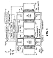
Fig. 3 is a top diagrammatic view of a first embodiment of a micromechanical comb drive tuning fork inertial rate sensor adapted for use as a thermally insensitive reference oscillator and radiation-hard precision voltage reference; -
Fig. 4 is a section view of the inertial rate sensor ofFig. 3 taken along lines 4-4; and -
Fig. 5 is a top diagrammatic view of a second embodiment of a micromechanical comb drive tuning fork inertial rate sensor adapted for use as a thermally insensitive reference oscillator and radiation-hard precision voltage reference; and -
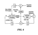
Fig. 6 is a block diagram of a simplified precision voltage reference according to the present invention. - The present invention contemplates a micromachined, thermally insensitive silicon resonator of silicon-on-glass fabrication having accuracy equivalent or superior to that of currently employed, thermally varying quartz resonators. In one embodiment, such a resonator is realized using a micromechanical, silicon-on-glass tuning fork gyroscope.
- In general and with reference to
Fig. 1 , a first thermally insensitive reference oscillator 5 is implemented by providing a reference voltage from anoscillator loop 8 to at least one sense or driveaxis force electrode 2 of a micromechanical silicon tuning fork gyroscope (TFG) 4 fabricated on a glass substrate. Theforce electrode 2 imparts motive force on a vibratory mass referred to above as aproof mass 1, wherein theproof mass 1 vibrates at a resonant frequency. At least onesense electrode 3 disposed proximate theproof mass 1 detects this oscillation, and returns a signal, modulated at the resonant frequency, to theoscillator loop 8 at a reference frequency fREF. Thesense electrode 3 is connected to thedrive electrode 2 through theoscillator loop 8. The mechanical frequency of oscillation and electrical output fREF are identical. - Other embodiments of the illustrated reference oscillator are fabricated from silicon-on-glass devices other than the aforementioned comb-drive tuning fork gyroscope.
- The present invention further contemplates a radiation-hard precision voltage reference (PVR) which is fabricated from a micromachined, thermally insensitive silicon resonator of silicon-on-glass fabrication, such as that shown schematically in
Fig. 1 . Because mechanical resonant frequencies are not changed by radiation, the PVR is radiation hard. Once again, a micromechanical, silicon-on-glass tuning fork gyroscope is employed in the realization of a first embodiment of the PVR, though other silicon-on-glass configurations are employable in alternative embodiments. - In
Fig. 2 , a precision voltage reference (PVR) 11 is fabricated from the silicon-on-glass, micromechanical tuning fork gyroscope (TFG) 4. As with the reference oscillator 5 just described, aproof mass 1 is excited into resonant motion by way of at least oneenergized force electrode 2 along either the sense or drive axes. Anoscillator loop 8 provides the AC excitation energy in this first embodiment. Afrequency control loop 21 compares a reference frequency fREF from afrequency standard 23 to a sensed proof mass oscillation frequency from theoscillator loop 8, and a DC correction signal is applied to theproof mass 1. Thus, the detected frequency of oscillation is synchronized with a reference frequency by adjusting an applied DC bias, which is then available as a reference voltage VREF. - The gyroscope employed in such realizations is a tuning fork gyroscope in which drive and driven electrode pairs, responsible for imparting vibrational motion to the tuning fork vibrating elements, are formed by plural respective interleaved fingers which greatly increase the area and capacitance as well as capacitance change with motion of the device so as to substantially enhance the system sensitivity. In addition, such a drive structure is consistent with fabrication techniques that allow for a greater mass to the vibrating element which cooperates with the higher efficiency drive in providing an increased sensitivity. The tuning fork structure has a high mechanical quality factor (Q), due to the opposing motion which tends to reduce the stress reaching the support points and hence reduce the coupling of energy out of the structure.
- The frequency stability of silicon flexures in a micromechanical device is significantly effected by the thermal sensitivity of Young's modulus. For a polysilicon oscillator structure disposed on a silicon substrate, frequency stability on the order of -10ppm/°C is typical. However, for a clock employing such an oscillator to be accurate to ten seconds per month requires frequency accuracy of 4 ppm over thermal variation, a figure routinely achieved by quartz tuning forks. By building tuning forks on a glass substrate and by employing proper flexure mechanical design, both as addressed herein, the thermal sensitivity of silicon oscillators is reduced two orders of magnitude to a performance level comparable with that of quartz.
- Alternative embodiments of a tuning fork rate sensitive structure 10 suitable for use in the realization of a thermally insensitive oscillator and a radiation hard, precision voltage reference (PVR) according to the present invention are illustrated in
Figs. 3, 4 and5 . The principles disclosed and claimed herein with respect to the depicted device 10 are equally applicable to other micromechanical device embodiments, though the test results presented are for the embodiment ofFigs. 3, 4 and5 only. - The gyroscope 10 comprises the following functional elements, illustrated with respect to
Figs. 3, 4 and5 . Twoproof masses 12 are each suspended above aglass substrate 14, and provide motion along two axes, X and Y. With regard toFigs. 3 and 4 , in which motion along the Y axis is utilized,sense 16 andforce 18 electrodes are disposed on theglass substrate 14, substantially beneathrespective proof masses 12, for imparting and detectingproof mass 12 motion along the Y axis. Thesense electrodes 16 provide information tosense electronics 17. Theforce electrodes 18, alternatively referred to as drive electrodes, are driven bydrive electronics 19. Collectively, the sense and drive electronics comprise theoscillator loop 8 illustrated inFigs. 1 and 2 . As inFig. 2 , thesense electronics 17 output is analyzed within thefrequency control loop 21 with respect to the frequency standard 23 output in order to generate a DC bias. This bias is applied to theproof mass 12 and serves as the reference voltage output (VREF). - In
Fig. 5 , motion along the X axis is employed to implement the reference oscillator and PVR. Here, eachproof mass 12 is provided with a plurality of proofmass fingers mass fingers proof mass fingers 20a and inner proofmass fingers 20b. Interspersed between the outerproof mass fingers 20a are outer fixedcomb fingers 22a extending from outer fixed combs 24. Interspersed between the inner proofmass fingers 20b are inner fixedcomb fingers 22b extending from inner fixed combs 26. The outerfixed combs 24 are connected to thedrive electronics 19 of theoscillator loop 8 and act as drive sources, so that the outerfixed comb fingers 22a act as drive electrodes. The capacitive effect between the outerfixed comb fingers 22a and the outerproof mass fingers 20a results in proof mass motion along the X axis. - This motion is detected by using the inner fixed
combs 26 as sense devices and the inner fixedcomb fingers 22b as sense electrodes, connected to thesense electronics 17. Capacitive variation sensed by the inner fixedcomb fingers 22b provides an indication of proof mass 12 X axis motion. The interleavedfingers Fig. 3 , the sensed frequency from thesense electronics 17 is analyzed in thefrequency control loop 21 with respect to the frequency standard 23 to generate the reference voltage. - Alternative labels include electrical signal source for drive electronics, and frequency module for sense electronics.
- In a further embodiment of the device of
Fig. 3 , in which only movement substantially parallel to the Y-axis is employed, the inner and outerproof mass fingers comb fingers - Similarly, in an alternative embodiment of the device of
Fig. 5 , the underlying sense andforce electrodes - A further embodiment of the present invention includes all of the force and sense elements of
Figs. 3 and5 , along with the respective electronics, such that this embodiment can be configured for use as a reference oscillator or a PVR, operating in either the Y or X axes. - To enable free movement of the
proof masses 12 in both the X and Y axes, theproof masses 12 are suspended from a system of beams and anchors. Specifically, fouranchors 30 are disposed on theglass substrate 14, proximate theelectrodes substrate 14. Extending away from eachanchor 30 and theproximate electrodes torsion beams 32. Disposed from thetorsion beams 32 laterally along the X axis arebase beams 34. Finally, extending between the base beams 34 and eachproof mass 12 are pairs of drive beams 36. Thus,proof mass 12 motion along both the X and Y axes is accommodated by the drive beams 36. Any residual strain or torque not compensated for by the drive beams 36 and conveyed through the base beams 34 is absorbed by the torsion beams 32. - The flat
force drive electrodes 18 deposited on thesubstrate 14 drive the proof mass Y motion which is sensed by the proximate sense electrodes 16 (Figs. 3 and 4 ). The outerfixed combs 24 driveproof mass 12 motion along the X axis, parallel to the surface of thesubstrate 14, which is detected by the inner fixed combs 26 (Fig. 5 ). - As previously indicated, if the substrate and micromachined parts are both made of silicon by a silicon-on-silicon technique, the resonant frequencies of both modes change on the order of -50 ppm/°C (negative coefficient) because of Young's modulus variation. This variation is significantly poorer than that achieved by quartz and required for many applications. Therefore, it is preferred to fabricate the sensor device of the present invention according to a silicon-on-glass technique, using, for instance, Pyrex™ (Corning) or similar glass as the substrate.
- Two features are of great importance in fabricating a thermally insensitive oscillator. The first is the use of glass as
substrate 14. The thermal coefficient of glass is on the order of 0.8 ppm/°C greater than that of crystalline silicon so that the Young's modulus and thermal expansion effects on device resonant frequency are opposite and self-cancelling. - Second, the thermal expansion effect within the
slender beams substrate 14. The suspension beam geometry as illustrated inFigs. 3 and5 , wherein eachproof mass 12 is suspended by not just one straight beam but by a combination of threebeams glass substrate 14. Further compensation for stress and torque can be incorporated into the presently illustrated gyroscope, such as by the use of folded support springs. - Both resonators (
Figs. 3 and5 ) have nonlinear stiffness so that the resonant frequency is a function of drive amplitude. This topic, briefly introduced here, is discussed in greater detail below. For simple oscillators, requirements for amplitude control are not stringent. With regard to the drive electronics for the X axis oscillator, the change in resonant frequency ω with drive amplitude x is described by:
- Assuming 2 µm amplitude with stability of 0.1%, the resonant frequency stability is 3.2 ppm, thus indicating that the requirements for drive axis amplitude are not stringent. High aspect ratio comb fingers further improve the capacitive sensitivity.
- Frequency variation with drive amplitude A for a sense or Y axis oscillator is described by:

where
ke = stiffness from electrostatic fields
kn = net mechanical and electrical stiffness
ω = resonant frequency.
For a tuning fork rate sensitive structure 10 as depicted with 5 V sense bias, the ratio of electric field to total stiffness is 0.024. Assuming the ratio of amplitude to nominal gap is 10% and that the amplitude is controlled to 0.1%, the change in eigenfrequency is 0.36 ppm. - Changes in package pressure affect damping, which in turn alters the force-displacement relationship at resonance. In environments where significant pressure differentials are expected, gain or amplitude control (not illustrated) is provided to the drive electronics so that pressure variations do not change the drive amplitude. As damping increases, the required drive voltage will increase. However, the effect of drive voltage on eigenfrequency is small. Gyro pressure variation does not then affect amplitude so that resonant frequency is not affected. Further, the effect of small thermal variations does not change the damping significantly.
- When the Young's modulus variation, thermal expansion difference, and strain relief are combined properly, the thermal sensitivity of the resonant frequency is greatly reduced, by approximately one to two orders of magnitude. Thus, the performance of oscillators formed from the silicon tuning fork approaches or exceeds that of quartz oscillators.
- A first precision voltage reference (PVR) employs the Y axis, or sense mode, of the gyroscope of
Figs. 3 and 4 . The sense and force functions are based on capacitive changes as theproof mass 12 moves normal to the plane of the sense and driveelectrodes sense electrodes 16, the electrostatic force acts as a negative spring proportional to the bias voltage squared. When the bias voltage is raised to the snap down voltage, the negative electrical spring overcomes the positive mechanical spring and the proof mass is unstable. The micromechanical device employed enables a PVR operable at reasonable voltages (e.g. 0-20 VDC). Silicon-on-Pyrex™ is an exemplary micromechanical device method. For the TFG embodiment 10 illustrated inFigs. 3 and5 , the snap down voltage is on the order of 18 V. Setting the sense electrode bias to 16 V results in an acceptable PVR where the resonant frequency is 21 kHz, compared to 28 kHz without electrical bias. - When operated with large excitations, the resonant frequency of the temperature insensitive silicon oscillator varies with voltage bias. As the bias approaches snap down, the eigenfrequency drops sharply. It is thus desired to operate close, but not too close, to snap down. For the illustrated embodiment, assume that the resonator is oscillating at 21.1 kHz, corresponding to 16.05 V bias or 90.2% of snap down. At a bias of 16 V, the 2.5 µm air gap between
proof mass 12 and thesubstrate 14 decreases 0.45 µm. The resonant frequency changes -2,190 Hz/V. Assume that the desired voltage stability is 0.2 ppm. The corresponding frequency stability is:
- The mechanical oscillator as previously described is configured into a voltage controlled oscillator loop via a
feedback circuit 21, or frequency comparator, disposed between thesense electronics 17 and thedrive electronics 19. The resonant frequency from the sense electronics is compared to afrequency standard 23. The bias voltage, which is treated as the reference voltage and is output from thedrive electronics 19, is adjusted to maintain the resonant frequency. Since the resonator is very stable and since frequency can be measured accurately, the precision voltage reference is realized. - To reiterate, the presently recited figures are for the illustrated device embodiments. Other device embodiments are possible, each having its own unique set of parameter values.
- With reference to
Fig. 6 , a simplified block diagram of the electronics required to implement a Y axis PVR according to the present invention is disclosed. The proof mass position signal, which is an AC signal at the oscillator eigenfrequency and is detected by the Y axis sense plates, is gained and integrated (or differentiated) to achieve proper phase for sustained oscillation. The resulting voltage is applied to the Y axis forcer plates which excites the oscillator dynamics as a fundamentally second order system. Since resonant frequency depends on the drive amplitude, an automatic gain control (AGC) loop is included. The absolute value or magnitude of the position signal is compared to a reference which adjusts the forcing voltage so that constant amplitude is maintained. The eigenfrequency depends on the bias voltage applied to the electrodes. This bias voltage is controlled by comparing the frequency of the Y axis position signal to a known frequency standard. Phase locked loops or counters can also be applied in alternative embodiments. - In a further embodiment of the present invention, torque electrodes are disposed next to (shown in
Fig. 3 as coincident with the anchors 30), inside or outside thesense electrodes 16 to apply forces to theproof mass 12. These torque voltages can be: 1) the torque bias, which may differ from the sense bias, plus a drive voltage at the eigenfrequency; 2) the torque bias plus a drive voltage at half resonance; or 3) two separate frequencies as used in the gyroscope drive. For the sense, or Y, axis PVR, bias equivalent to the sense bias plus drive voltage is the most attractive because the small voltage required to probe the resonance does not alter the eigenfrequency. - In a further embodiment of the present invention, temperature control or compensation is provided in order to achieve the desired frequency stability of 0.3 ppm.
- The resonant frequency and hence the controlled voltage stability depends upon the amplitude of the oscillation and also on the voltage applied to the drive electrodes. Consider the stability required of the oscillating position. When the two
proof masses 12 are balanced, the sense force versus displacement includes a cubic term along with the desired negative linear spring, which contributes to the resonant frequency. At motion which is 1% of the air gap and at 16 V sense excitation, the ratio of electrical to total stiffness is the cubic term, which contributes a frequency shift of 8.2 x 10⁻⁵ times the nominal resonant frequency. With reference to Eq. 2, if the drive voltage amplitude is maintained to 1000 ppm (1 µV), the frequency shifts 0.16 ppm (2 x 8.2 x 10-5 x 0.001). Since the drive voltage is 1 mV, voltage dividers enable the required 1 µV stability. - Any voltages applied to drive the proof mass can alter the resonant frequency. The proof mass must be driven to probe for the resonant frequency. Consider the previous parameters with bias plus drive voltage. With 16 V applied to bias the sense axis force and sense electrodes, 1 mV drive voltage moves the
sense axis 1 % of the 2.5 µm nominal gap. The area of the torque electrodes is 10% that of the sense plus torque electrodes. The DC force and stiffness generated by the probe signal is only 2.0 x 10⁻¹⁰ that of the bias signal ((0.001/16)2 x 0.1/2) so that the probe voltage can change and the PVR will satisfy its 0.2 ppm voltage stability (0.32 ppm frequency stability) requirement. - As a second option, consider drive frequency at half the eigenfrequency. The cos 2ωt is at the sense eigenfrequency (eq. 10). To achieve motion of 1% of the air gap with the torque electrode 10% the proof mass area, the drive voltage must be 0.25 V. The DC force and stiffness generated by the probe signal is 1.3 x 10⁻⁵ ((0.25/16)2 x 0.1/2) that generated by the bias signal. With modest pressure stability, the drift of the probe signal should be adequate to control precisely the bias signal. The size of the first harmonic compared to the cos 2ωt term must be considered in oscillator design. Half-frequency drive is taught in
U.S. Patent No. 5,481,914 to Ward , "Electronics for Coriolis Force and Other Sensors." - A second PVR employs X axis motion, or motion parallel to the substrate, as shown in
Fig. 5 . The gyroscope drive motion is excited by the outer fixedcomb drive fingers 22a and detected by the inner fixedcomb fingers 22b. As the proof mass X amplitude increases, tension in thebeams 36 increases so that the stiffness becomes nonlinear. The resonant frequency increases with drive amplitude which is determined by the drive voltage. Because the resonant frequency and drive amplitude are intimately linked, damping resulting from ambient pressure must be tightly controlled so that the drive amplitude and resonant frequency do not vary. As a result, the X axis PVR is considered less desirable than the Y axis PVR. Unlike the sense or Y axis PVR, the eigenfrequency cannot be set independently of motion amplitude. - In one embodiment of a drive axis PVR, a half-frequency drive, such as that taught in the above-referenced patent, establishes the motion amplitude so the resonant frequency depends only upon one voltage. The amplitude of the half-frequency drive can be the precisely controlled voltage reference. The half-frequency is obtained from a DC voltage by chopping with low leakage switches.
- For a tuning fork gyro as depicted with half-frequency drive, 6 V of amplitude applied to the outer
fixed comb fingers 22a results in 20 µm drive amplitude. 25.5 kHz small amplitude eigenfrequency increases to 29.7 kHz and the change in eigenfrequency with drive amplitude is 2360 Hz/V. According to the following equation:
- Since the change in voltage is seen as a change in motion amplitude which alters resonant frequency, the precision voltage control is the amplitude control loop. Motion amplitude cannot be controlled independently of eigenfrequency. If the pressure and damping constant change 0.1%, the motor drive force must also change 0.1% to maintain amplitude. With half-frequency drive, the reference voltage changes 0.05%. The drive axis PVR therefore requires excellent control of damping and hence ambient pressure.
- The following is a discussion of changes in beam eigenfrequency with temperature.
- Consider a proof mass supported by beams built-in at either end. This is similar to the tuning fork gyro of
Fig. 5 with thebase beam 34 not moving, the nominal situation for drive axis dynamics. Thermal expansion coefficient difference between thesubstrate 14 and the silicon parts results in axial strains in the suspension beams. Because the beams are rectangular, the changes in resonant frequencies for the sense and drive axes differ so that only one axis will be thermally insensitive. The following analysis calculates stiffness with tension based on straight suspension beams. Except for the stress reduction factor, the base region is omitted from the natural frequency calculation, a first approximation. The axial load in one suspension beam is estimated from:
where αsbst = thermal expansion coefficient of the substrate.
α = thermal expansion coefficient of silicon
lm = proof mass length
lt = length of torsion bar
ΔTg = change in gyro temperature
Sred = stress reduction afforded by the suspension (the base is compliant) - With axial tension P, the X direction force is related to displacement by:

where and I = area moments of inertia - Expand (6) in a Taylor series around P = 0. For a single proof mass with 2N beams of
length 1/2 with two built-in ends, the force required to achieve a displacement x is:
where I = the area moment of inertia for one beam - In (7), the first term is the stiffness calculated from simple beam theory without axial tension. The entire expression is the stiffness with axial load. For silicon, the Young's modulus decreases with temperature, roughly -100 ppm/°C. The substrate should have higher expansion coefficient than the silicon so that the load applied to the beams is positive, opposite in sign to the linear term. Neglecting the P2 terms and using I = bh3/12 and P = Ebh e where e is the axial strain:

- Treat E = E + ΔE and e as first order terms and neglect second order terms. For silicon the thermal expansion coefficient of silicon is 2.5 ppm/°C and is neglected. With the incremental terms, the stiffness is:

- For the tuning fork gyro of
Figs. 3 and5 , h is 5 to 8 µm for drive and sense axes respectively. The length is 400 µm so that the first term in brackets is -0.06 to -0.16 ppm/°C. The differential thermal expansion between silicon and glass is of the order of +1 ppm/°C; thus strain relief as provided is required to cancel the variation in stiffness with frequency. - The following is a discussion of sense axis electrostatic relationships.
- As a starting point, consider the force and stiffness aspects of the tuning fork gyro 10 of
Fig. 3 . If the proof mass is grounded and a bias voltage is applied to the sense electrode, an electrostatic force is applied to the proof mass. For parallel plates, the force on the proof mass is described by:
where h = nominal air gap
y = deviation of air gap from nominal, the vertical motion of the proof mass
εo = permittivity of low pressure air (8.85 x 10⁻¹² F/m)
A = area of plates
V = voltage applied to the electrode
km = mechanical stiffness
Fe = electrostatic force
Fm = mechanical force from suspension springs - The negative sign for the electrostatic force indicates that the proof mass is pulled toward the electrode since h + y ≥ 0. Differentiating (10), the stiffness is given by:

- The effective stiffness and, hence, the resonant frequency are modified by the electrostatic forces which depend on the bias voltage V. With small bias voltage, the proof mass deviates little from the nominal gap h. As V increases, static balance (10) dictates that the proof mass move closer to the electrode; that is, the displacement y is negative. As the voltage increases and the air gap (h + y) decreases, the force (10) and the stiffness (11) equal zero when the bias voltage and the displacement are:


- For larger voltage, the system is unstable and the mass "snaps down" into contact with the electrode.
- For the Y axis PVR, the following shows that electric field non-linear behavior does not result in excessive PVR error. Besides the bias (the precision reference), a drive voltage must be applied to excite or probe the resonant frequency. As previously suggested in
Fig. 3 , assume that the proof mass is biased at VB and that a drive voltage is applied at frequency ω. The electric field force is:
- Rearranging (14)

where As = area sense electrode
At = area torque electrode
VB = bias voltage
VD = drive voltage - Using the foregoing, the frequency variation from nonlinear stiffness is analyzed by expanding the position terms in the denominator of (15) into the following power series:

- The quadratic terms cancel by push-pull and do not contribute to resonant frequency. For small changes in resonant frequency Δω, the change in resonant frequency caused by the cubic in (16) is given by equation (2).
- These and other examples of the invention illustrated above are intended by way of example and the actual scope of the invention is to be determined from the following claims.
Claims (16)
- A frequency or voltage reference device (5) employing a micromechanical, silicon tuning fork gyroscope (4) disposed on a glass substrate (14) and having a proof mass (1) translated by a force electrode (2) and sensed by a sense electrode (3), said device(5) comprising:a voltage source (19) proximate said gyroscope (4) providing a voltage signal to said force electrode (2); andsense electronics (17) proximate said gyroscope (4) and in communication with said sense electrode (3) for receiving a proof mass motion signal and for providing a reference frequency extracted therefrom.
- The device according to claim 1, further comprising a gain control circuit in communication with said voltage source.
- The device according to claim 1 further comprising:a frequency generator (21) proximate said gyroscope (4) for providing a reference frequency; wherein
the sense electronics (17) are adapted to receive said reference frequency from said frequency generator (21) and to generate a difference signal between said proof mass motion signal and said reference frequency,wherein said voltage source (19) receives said difference signal and adjusts said voltage signal based thereupon, said voltage source (19) providing said voltage signal as a voltage reference. - The device according to claim 1, wherein the device is a micromechanical, thermally insensitive and radiation hard reference device fabricated from a micromechanical silicon-on-glass structure, the device further comprising:a substantially planar glass substrate (14);at least one silicon anchor (30) disposed on said substrate (14);a plurality of silicon beams (32, 36) extending from said at least one anchor (30) and parallel to said substrate (14); anda first weighted element (12) suspended from said plurality of beams (32, 36) above said substrate (14) and relocatable along a first axis substantially orthogonal to said planar substrate (14); whereinthe force electrode of the micromechanical, silicon tuning fork gyroscope (4), is disposed on said substrate, substantially beneath said first weighted element,the voltage source includes a first electrical signal source (19) in electrical communication with said force electrode (18) for providing a first alternating potential between said force electrode (18) and said first weighted element (12) to cause said first weighted element (12) to oscillate along said first axis,the sense electrode (16) is disposed proximate said force electrode (18) on said substrate (14), substantially beneath said first weighted element (12), andthe sense electronics include a first frequency module (17) proximate said reference device (23) for receiving an electrical signal from said sense electrode (16) reflective of capacitive fluctuations between said sense electrode (16) and said first weighted element (12) during relocation of said first weighted element (12) along said first axis, said first frequency module (17) providing a reference frequency resulting from the frequency of sensed capacitive fluctuations.
- The device according to claim 4, further comprising:a first frequency comparator (21) in communication with said first frequency module (17) for comparing said first measured frequency with a reference frequency and for providing an offset signal to said first electrical signal source (19),wherein said first electrical signal source (19) provides said first alternating potential as a first reference voltage.
- The device according to claim 4, further comprising a gain control circuit in communication with said first electrical signal source (19).
- The device according to claim 4, further comprising:a second weighted element (12) suspended from said plurality of beams (32, 36) above said substrate (14) and translatable along a second axis substantially orthogonal to said first axis and parallel said substrate (14);a set of driven finger electrodes (20a, 20b) projecting from said second weighted element (12) substantially parallel said second axis;a set of drive finger electrodes (22a) substantially parallel to and freely meshing with a first subset of said set of driven finger electrodes (20a);a second electrical signal source (19) in electrical communication with said first subset of driven finger electrodes (20a) and said set of drive finger electrodes (22a) for providing a second alternating potential between said driven (20a) and drive finger electrodes (22a) to induce vibration of said second weighted element (12) along said second axis;a set of sense finger electrodes (22b) substantially parallel to and freely meshing with a second subset of said driven finger electrodes (20b); anda second frequency module (17) proximate said reference device (21) and receiving an electrical signal from said sense finger electrodes (22b) reflective of capacitive fluctuations between said sense finger electrodes (22b) and said second subset of driven finger electrodes (20b) during said vibration of said second weighted element (12) along said second axis, said second frequency module (17) providing a second measured frequency equivalent to the frequency of sensed capacitive fluctuations.
- The device according to claim 7, further comprising:a second frequency comparator (21) in communication with said second frequency module (17) for comparing said second measured frequency with a reference frequency and for providing an offset signal to said second electrical signal source (19),wherein said second electrical signal source (19) provides said second alternating potential as a second reference voltage.
- The device according to claim 7, further comprising a gain control circuit in communication with said second electrical signal source (19).
- The device according to claim 7, wherein said first and second weighted elements (12) are each comprised of complimentary left and right portions parallel to said substrate.
- The device according to claim 1 further comprising:a substantially planar glass substrate (14); whereinthe micromechanical, silicon tuning fork gyroscope (4) includes :a plurality of silicon anchors (30) disposed on said substrate (14),a plurality of silicon beams (32, 36) extending from said plurality of anchors (30), parallel to said substrate (14),first and second weighted elements (12) each suspended from respective ones of said plurality of beams (32, 36) above said substrate (14), said weighted elements (12) rotatable about a first axis parallel and above said substrate (14),at least one force electrode (18) disposed on said substrate (14) under each of said first and second weighted elements (12), andat least one sense electrode (16) disposed on said substrate (14) under each of said first and second weighted elements (12);a first source of electrical bias (19) in communication with said at least one force electrode (18) for establishing an alternating bias between each of said weighted elements (12) and respective force electrodes (18) for oscillating said weighted elements (12) about said first axis; anda first frequency module (17) in communication with said at least one sense electrode (16) for determining a frequency of capacitive fluctuation between said weighted elements (12) and respective sense electrodes (16) during oscillation of said weighted elements (12) about said first axis and for providing a reference frequency resulting from the frequency reflective of said capacitive fluctuation.
- The device according to claim 11, wherein
said first and second weighted elements (12) are further translatable along a second axis substantially orthogonal to said first axis and parallel said substrate (14). - The device according to claim 12, further comprising:a set of driven finger electrodes (20a, 20b) projecting from each of said weighted elements (12) substantially parallel said second axis;a set of drive finger electrodes (22a), disposed on drive anchors (24) attached to said substrate (14), said drive finger electrodes (22a) substantially parallel to and freely meshing with a first subset of said set of driven finger electrodes (20a);a second source of electrical bias (19) in communication with said first subset of driven finger electrodes (20a) and said set of drive finger electrodes (22a) for providing an alternating bias between said driven (20a) and drive finger electrodes (22a) for translating said weighted elements (12) along said second axis;a set of sense finger electrodes (22b), disposed on sense anchors (26) attached to said substrate (14), said sense finger electrodes (22b) substantially parallel to and freely meshing with a second subset of said driven finger electrodes (20b);a second frequency module (17) in communication with said set of sense finger electrodes (22b) for determining a frequency of capacitive fluctuation between said set of sense electrodes (22b) and said second subset of said driven finger electrodes (20b) during translation of said weighted elements (12) along said second axis and for providing a second measured frequency reflective of said capacitive fluctuation.
- The device according to claim 1 further comprising:a substantially planar glass substrate (14); whereinthe micromechanical, silicon tuning fork gyroscope (4) includes:a plurality of silicon anchors (30) disposed on said substrate (14),a plurality of silicon beams (32, 36) extending from said plurality of anchors (30), parallel to said substrate (14),first and second weighted elements (12) each suspended from respective ones of said plurality of beams (32, 36) above said substrate (14), said weighted elements (12) rotatable about a first axis parallel and above said substrate (14),at least one force electrode (18) disposed on said substrate (14) under each of said first and second weighted elements (12), andat least one sense electrode (16) disposed on said substrate (14) under each of said first and second weighted elements (12);a first source of electrical bias (19) in communication with said at least one force electrode (18) for establishing an alternating bias between each of said weighted elements (12) and respective force electrodes for oscillating said weighted elements (12) about said first axis;a first frequency module (17) in communication with said at least one sense electrode (16) for determining a frequency of capacitive fluctuation between said weighted elements (12) and respective sense electrodes (16) during oscillation of said weighted elements (12) about said first axis and for providing a first measured frequency reflective of said capacitive fluctuation; anda first frequency comparator (21) for comparing said first measured frequency with a frequency standard and for providing said first source of electrical bias with a first feedback signal,wherein said first source of electrical bias provides a first bias standard.
- The device according to claim 14, wherein
said first and second weighted elements (12) are further translatable along a second axis substantially orthogonal to said first axis and parallel said substrate (14). - The device according to claim 15, further comprising:a set of driven finger electrodes (20a, 20b) projecting from each of said weighted elements (12) substantially parallel said second axis;a set of drive finger electrodes (22a), disposed on drive anchors (24) attached to said substrate (14), said drive finger electrodes (22a) substantially parallel to and freely meshing with a first subset of said set of driven finger electrodes (20a);a second source of electrical bias in communication with said first subset of driven finger electrodes (20a) and said set of drive finger electrodes (22a) for establishing an alternating bias between said driven (20a) and drive finger electrodes (22a) for translating said weighted elements (14) along said second axis;a set of sense finger electrodes (22b), disposed on sense anchors (26) attached to said substrate (14), said sense finger electrodes (22b) substantially parallel to and freely meshing with a second subset of said driven finger electrodes (20b);a second frequency module (17) in communication with said set of sense finger electrodes (22b) for determining a frequency of capacitive fluctuation between said set of sense electrodes (22b) and said second subset of said driven finger electrodes (20b) during translation of said weighted elements (12) along said second axis and for providing a second measured frequency reflective of said capacitive fluctuation; anda second frequency comparator (21) for comparing said second measured frequency with a frequency standard and for providing said second source of electrical bias (19) with a second feedback signal,wherein said second source of electrical bias (19) provides a second bias standard.
Applications Claiming Priority (3)
| Application Number | Priority Date | Filing Date | Title |
|---|---|---|---|
| US08/804,796 US5783973A (en) | 1997-02-24 | 1997-02-24 | Temperature insensitive silicon oscillator and precision voltage reference formed therefrom |
| US804796 | 1997-02-24 | ||
| PCT/US1998/003619 WO1998037635A1 (en) | 1997-02-24 | 1998-02-24 | Temperature insensitive silicon oscillator and precision voltage reference formed therefrom |
Publications (3)
| Publication Number | Publication Date |
|---|---|
| EP0962052A1 EP0962052A1 (en) | 1999-12-08 |
| EP0962052A4 EP0962052A4 (en) | 2002-03-27 |
| EP0962052B1 true EP0962052B1 (en) | 2009-01-14 |
Family
ID=25189859
Family Applications (1)
| Application Number | Title | Priority Date | Filing Date |
|---|---|---|---|
| EP98910052A Expired - Lifetime EP0962052B1 (en) | 1997-02-24 | 1998-02-24 | Temperature insensitive silicon oscillator and precision voltage reference formed therefrom |
Country Status (6)
| Country | Link |
|---|---|
| US (1) | US5783973A (en) |
| EP (1) | EP0962052B1 (en) |
| JP (1) | JP4343273B2 (en) |
| CA (1) | CA2282604A1 (en) |
| DE (1) | DE69840474D1 (en) |
| WO (1) | WO1998037635A1 (en) |
Families Citing this family (69)
| Publication number | Priority date | Publication date | Assignee | Title |
|---|---|---|---|---|
| DE19807663A1 (en) * | 1998-02-24 | 1999-09-09 | Baur | Connection means for releasably connecting a first component and a second component and method for releasing a connection of a first component and a second component |
| US6230563B1 (en) | 1998-06-09 | 2001-05-15 | Integrated Micro Instruments, Inc. | Dual-mass vibratory rate gyroscope with suppressed translational acceleration response and quadrature-error correction capability |
| US6424074B2 (en) | 1999-01-14 | 2002-07-23 | The Regents Of The University Of Michigan | Method and apparatus for upconverting and filtering an information signal utilizing a vibrating micromechanical device |
| US6593831B2 (en) | 1999-01-14 | 2003-07-15 | The Regents Of The University Of Michigan | Method and apparatus for filtering signals in a subsystem including a power amplifier utilizing a bank of vibrating micromechanical apparatus |
| US6600252B2 (en) | 1999-01-14 | 2003-07-29 | The Regents Of The University Of Michigan | Method and subsystem for processing signals utilizing a plurality of vibrating micromechanical devices |
| US6713938B2 (en) | 1999-01-14 | 2004-03-30 | The Regents Of The University Of Michigan | Method and apparatus for filtering signals utilizing a vibrating micromechanical resonator |
| US6577040B2 (en) | 1999-01-14 | 2003-06-10 | The Regents Of The University Of Michigan | Method and apparatus for generating a signal having at least one desired output frequency utilizing a bank of vibrating micromechanical devices |
| US6566786B2 (en) | 1999-01-14 | 2003-05-20 | The Regents Of The University Of Michigan | Method and apparatus for selecting at least one desired channel utilizing a bank of vibrating micromechanical apparatus |
| DE60037132T2 (en) | 2000-12-21 | 2008-09-11 | Eta Sa Manufacture Horlogère Suisse | Time reference with an integrated micromechanical tuning fork resonator |
| US6958566B2 (en) * | 2001-08-16 | 2005-10-25 | The Regents Of The University Of Michigan | Mechanical resonator device having phenomena-dependent electrical stiffness |
| US6598475B2 (en) | 2001-09-20 | 2003-07-29 | Honeywell International Inc. | Micromechanical inertial sensor having increased pickoff resonance damping |
| WO2003055063A1 (en) * | 2001-12-06 | 2003-07-03 | University Of Pittsburgh | Tunable piezoelectric micro-mechanical resonator |
| EP1472507B1 (en) * | 2002-02-06 | 2011-05-11 | Analog Devices, Inc. | Micromachined gyroscope |
| US7089792B2 (en) * | 2002-02-06 | 2006-08-15 | Analod Devices, Inc. | Micromachined apparatus utilizing box suspensions |
| US6837108B2 (en) | 2002-04-23 | 2005-01-04 | Honeywell International Inc. | Increasing the dynamic range of a MEMS gyroscope |
| US6987432B2 (en) * | 2003-04-16 | 2006-01-17 | Robert Bosch Gmbh | Temperature compensation for silicon MEMS resonator |
| FR2854992B1 (en) * | 2003-05-15 | 2005-07-01 | Suisse Electronique Microtech | ARCHITECTURE FOR TIME BASE |
| US6843127B1 (en) * | 2003-07-30 | 2005-01-18 | Motorola, Inc. | Flexible vibratory micro-electromechanical device |
| US7370531B2 (en) * | 2004-01-20 | 2008-05-13 | Ngk Insulators, Ltd. | Detection circuits, detection method and systems of measuring physical quantities |
| JP4512636B2 (en) * | 2004-04-14 | 2010-07-28 | アナログ デバイシス, インコーポレイテッド | Inertial sensor with linearly arrayed sensor elements |
| JP4576898B2 (en) * | 2004-06-18 | 2010-11-10 | セイコーエプソン株式会社 | Micromechanical electrostatic vibrator |
| DE602004023082D1 (en) * | 2004-09-22 | 2009-10-22 | St Microelectronics Srl | Micro-electromechanical structure with self-compensation of thermal drift caused by thermo-mechanical stresses |
| US7478557B2 (en) * | 2004-10-01 | 2009-01-20 | Analog Devices, Inc. | Common centroid micromachine driver |
| EP1645847B1 (en) * | 2004-10-08 | 2014-07-02 | STMicroelectronics Srl | Temperature compensated micro-electromechanical device and method of temperature compensation in a micro-electromechanical device |
| CA2592169A1 (en) | 2005-01-07 | 2006-08-10 | Trustees Of Boston University | Nanomechanical oscillator |
| US7421897B2 (en) | 2005-04-14 | 2008-09-09 | Analog Devices, Inc. | Cross-quad and vertically coupled inertial sensors |
| US8314665B2 (en) | 2006-09-20 | 2012-11-20 | Trustees Of Boston University | Nano electromechanical integrated-circuit filter |
| US7409862B2 (en) * | 2006-10-18 | 2008-08-12 | Honeywell International Inc. | Systems and methods for isolation of torque and sense capacitors of an accelerometer |
| US8772999B2 (en) | 2007-10-11 | 2014-07-08 | Sand 9, Inc. | Signal amplification by hierarchal resonating structures |
| JP5162206B2 (en) * | 2007-11-12 | 2013-03-13 | セイコーインスツル株式会社 | Oscillator, oscillator manufacturing method, and oscillator |
| US7990229B2 (en) | 2008-04-01 | 2011-08-02 | Sand9, Inc. | Methods and devices for compensating a signal using resonators |
| US8044736B2 (en) | 2008-04-29 | 2011-10-25 | Sand9, Inc. | Timing oscillators and related methods |
| US8410868B2 (en) | 2009-06-04 | 2013-04-02 | Sand 9, Inc. | Methods and apparatus for temperature control of devices and mechanical resonating structures |
| US8476809B2 (en) | 2008-04-29 | 2013-07-02 | Sand 9, Inc. | Microelectromechanical systems (MEMS) resonators and related apparatus and methods |
| US8044737B2 (en) | 2008-04-29 | 2011-10-25 | Sand9, Inc. | Timing oscillators and related methods |
| US8187902B2 (en) | 2008-07-09 | 2012-05-29 | The Charles Stark Draper Laboratory, Inc. | High performance sensors and methods for forming the same |
| US8111108B2 (en) | 2008-07-29 | 2012-02-07 | Sand9, Inc. | Micromechanical resonating devices and related methods |
| DE102008054369B4 (en) | 2008-12-08 | 2024-05-23 | Robert Bosch Gmbh | Resonator, rotation rate sensor with resonator, manufacturing method for a resonator and method for setting a natural frequency of a resonator |
| US7843277B2 (en) * | 2008-12-16 | 2010-11-30 | Immersion Corporation | Haptic feedback generation based on resonant frequency |
| US8689426B2 (en) | 2008-12-17 | 2014-04-08 | Sand 9, Inc. | Method of manufacturing a resonating structure |
| US8686614B2 (en) | 2008-12-17 | 2014-04-01 | Sand 9, Inc. | Multi-port mechanical resonating devices and related methods |
| US8456250B2 (en) | 2009-02-04 | 2013-06-04 | Sand 9, Inc. | Methods and apparatus for tuning devices having resonators |
| US8446227B2 (en) | 2009-02-04 | 2013-05-21 | Sand 9, Inc. | Methods and apparatus for tuning devices having mechanical resonators |
| US8395456B2 (en) | 2009-02-04 | 2013-03-12 | Sand 9, Inc. | Variable phase amplifier circuit and method of use |
| US9048811B2 (en) | 2009-03-31 | 2015-06-02 | Sand 9, Inc. | Integration of piezoelectric materials with substrates |
| JP5240045B2 (en) * | 2009-04-23 | 2013-07-17 | 旭化成エレクトロニクス株式会社 | Driving method and driving circuit for vibrator, and inertial force detection device including the driving circuit |
| US8314585B2 (en) * | 2009-09-25 | 2012-11-20 | Drs Rsta, Inc. | Methods and systems for eliminating structural modes in a servo mechanism employed to control a flexible structure |
| US9038459B1 (en) * | 2009-12-14 | 2015-05-26 | Hrl Laboratories, Llc | Frequency locking of resonators for improved temperature control of gyroscopes |
| US8228127B2 (en) | 2009-12-23 | 2012-07-24 | Sand 9, Inc. | Oscillators having arbitrary frequencies and related systems and methods |
| US8704604B2 (en) | 2009-12-23 | 2014-04-22 | Sand 9, Inc. | Oscillators having arbitrary frequencies and related systems and methods |
| US8604888B2 (en) | 2009-12-23 | 2013-12-10 | Sand 9, Inc. | Oscillators having arbitrary frequencies and related systems and methods |
| US8661899B2 (en) | 2010-03-01 | 2014-03-04 | Sand9, Inc. | Microelectromechanical gyroscopes and related apparatus and methods |
| GB201005875D0 (en) * | 2010-04-08 | 2010-05-26 | Silicon Sensing Systems Ltd | Sensors |
| WO2011133682A1 (en) | 2010-04-20 | 2011-10-27 | Guiti Zolfagharkhani | Microelectromechanical gyroscopes and related apparatus and methods |
| US9075077B2 (en) | 2010-09-20 | 2015-07-07 | Analog Devices, Inc. | Resonant sensing using extensional modes of a plate |
| US8988061B2 (en) | 2011-02-10 | 2015-03-24 | U.S. Department Of Energy | Nanomechanical electric and electromagnetic field sensor |
| US9383208B2 (en) | 2011-10-13 | 2016-07-05 | Analog Devices, Inc. | Electromechanical magnetometer and applications thereof |
| US9224435B2 (en) | 2013-08-22 | 2015-12-29 | The Charles Stark Draper Laboratory, Inc. | Radiation-hard precision voltage reference |
| US10823754B2 (en) | 2014-11-14 | 2020-11-03 | Honeywell International Inc. | Accelerometer with strain compensation |
| US9689888B2 (en) | 2014-11-14 | 2017-06-27 | Honeywell International Inc. | In-plane vibrating beam accelerometer |
| US9979088B2 (en) | 2015-02-02 | 2018-05-22 | The Charles Stark Draper Laboratory, Inc. | Mechanical antenna |
| US10200036B1 (en) | 2015-06-30 | 2019-02-05 | The Charles Stark Draper Laboratory, Inc. | Radiation-hard precision voltage reference |
| US10109161B2 (en) | 2015-08-21 | 2018-10-23 | Immersion Corporation | Haptic driver with attenuation |
| ITUA20162173A1 (en) | 2016-03-31 | 2017-10-01 | St Microelectronics Srl | ACCELEROMETRIC MEMS SENSOR HAVING HIGH ACCURACY AND REDUCED SENSITIVITY TOWARDS TEMPERATURE AND AGING |
| EP3361216B1 (en) * | 2017-02-08 | 2021-04-28 | Murata Manufacturing Co., Ltd. | System and method for resonator amplitude control |
| CN109141473B (en) * | 2018-08-17 | 2022-09-13 | 北方电子研究院安徽有限公司 | Variable damping MEMS gyro sensitive structure testing device |
| US11307217B1 (en) | 2019-06-21 | 2022-04-19 | Facebook Technologies, Llc | Resonant accelerometer |
| US11333679B1 (en) * | 2019-06-21 | 2022-05-17 | Facebook Technologies, Llc | Electrostatically softened accelerometer spring |
| DE102022126948A1 (en) * | 2022-10-14 | 2024-04-25 | Northrop Grumman Litef Gmbh | Method and device for measuring a voltage |
Family Cites Families (124)
| Publication number | Priority date | Publication date | Assignee | Title |
|---|---|---|---|---|
| US32931A (en) * | 1861-07-30 | Machine for tupvning tapering forms | ||
| US33479A (en) * | 1861-10-15 | Improved blacksmith s portable forge | ||
| CH359552A (en) * | 1957-07-20 | 1962-01-15 | Boelkow Entwicklungen Kg | Measuring and control device for very low speeds |
| GB989101A (en) * | 1961-07-11 | 1965-04-14 | Mini Of Aviat London | Improvements in gyroscope apparatus |
| US3370458A (en) * | 1965-09-10 | 1968-02-27 | W C Dillon & Company Inc | Mechanical force gauge |
| US3696429A (en) * | 1971-05-24 | 1972-10-03 | Cutler Hammer Inc | Signal cancellation system |
| US3736740A (en) * | 1971-10-22 | 1973-06-05 | Novox Inc | Electromagnetic timing mechanism |
| US3913035A (en) * | 1974-07-01 | 1975-10-14 | Motorola Inc | Negative resistance high-q-microwave oscillator |
| US4044305A (en) * | 1975-03-17 | 1977-08-23 | The Charles Stark Draper Laboratory, Inc. | Apparatus for providing a displacement representative of the magnitude of a signal |
| JPS6025926B2 (en) * | 1976-10-01 | 1985-06-21 | シャープ株式会社 | Crystal oscillator |
| US4155257A (en) * | 1977-05-23 | 1979-05-22 | The Singer Company | Temperature compensated vibrating beam accelerometer |
| US4122448A (en) * | 1977-07-21 | 1978-10-24 | Westinghouse Electric Corp. | Automatic phase and gain balance controller for a baseband processor |
| US4144764A (en) * | 1978-05-11 | 1979-03-20 | Schaevitz Engineering | Servo amplifier for an electrically damped accelerometer |
| US4234666A (en) * | 1978-07-26 | 1980-11-18 | Western Electric Company, Inc. | Carrier tapes for semiconductor devices |
| US4321500A (en) * | 1979-12-17 | 1982-03-23 | Paroscientific, Inc. | Longitudinal isolation system for flexurally vibrating force transducers |
| US4336718A (en) * | 1980-09-08 | 1982-06-29 | Lear Siegler, Inc. | Control circuit for accelerometer |
| US4342227A (en) * | 1980-12-24 | 1982-08-03 | International Business Machines Corporation | Planar semiconductor three direction acceleration detecting device and method of fabrication |
| US4499778A (en) * | 1981-02-03 | 1985-02-19 | Northrop Corporation | Flexure mount assembly for a dynamically tuned gyroscope and method of manufacturing same |
| US4381672A (en) * | 1981-03-04 | 1983-05-03 | The Bendix Corporation | Vibrating beam rotation sensor |
| US4447753A (en) * | 1981-03-25 | 1984-05-08 | Seiko Instruments & Electronics Ltd. | Miniature GT-cut quartz resonator |
| DE3112560C2 (en) * | 1981-03-30 | 1983-01-27 | M.A.N.- Roland Druckmaschinen AG, 6050 Offenbach | Proximity switch which, by means of excitation and detection of a field, indicates the presence or absence of field-changing objects in a defined distance range from the proximity switch using a binary signal |
| US4406992A (en) * | 1981-04-20 | 1983-09-27 | Kulite Semiconductor Products, Inc. | Semiconductor pressure transducer or other product employing layers of single crystal silicon |
| JPS57188121A (en) * | 1981-05-15 | 1982-11-19 | Seiko Instr & Electronics Ltd | Frequency adjusting method of coupling oscillator |
| CH642461A5 (en) * | 1981-07-02 | 1984-04-13 | Centre Electron Horloger | ACCELEROMETER. |
| US4495499A (en) * | 1981-09-08 | 1985-01-22 | David Richardson | Integrated oscillator-duplexer-mixer |
| US4414852A (en) * | 1981-09-14 | 1983-11-15 | Gould Inc. | Automatic zero balance circuit |
| US4654663A (en) * | 1981-11-16 | 1987-03-31 | Piezoelectric Technology Investors, Ltd. | Angular rate sensor system |
| US4411741A (en) * | 1982-01-12 | 1983-10-25 | University Of Utah | Apparatus and method for measuring the concentration of components in fluids |
| DE3213720C2 (en) * | 1982-04-14 | 1985-09-05 | Bodenseewerk Gerätetechnik GmbH, 7770 Überlingen | Dynamically coordinated cardan suspension with two degrees of freedom |
| US4478076A (en) * | 1982-09-30 | 1984-10-23 | Honeywell Inc. | Flow sensor |
| US4651564A (en) * | 1982-09-30 | 1987-03-24 | Honeywell Inc. | Semiconductor device |
| US4478077A (en) * | 1982-09-30 | 1984-10-23 | Honeywell Inc. | Flow sensor |
| US4621925A (en) * | 1982-11-11 | 1986-11-11 | Fujitsu Limited | Fiber-optic gyro |
| US4596158A (en) * | 1983-01-05 | 1986-06-24 | Litton Systems, Inc. | Tuned gyroscope with dynamic absorber |
| US4522072A (en) * | 1983-04-22 | 1985-06-11 | Insouth Microsystems, Inc. | Electromechanical transducer strain sensor arrangement and construction |
| US4490772A (en) * | 1983-06-13 | 1984-12-25 | Blickstein Martin J | Voltage and mechanically variable trimmer capacitor |
| US4619001A (en) * | 1983-08-02 | 1986-10-21 | Matsushita Electric Industrial Co., Ltd. | Tuning systems on dielectric substrates |
| US4590801A (en) * | 1983-09-02 | 1986-05-27 | Sundstrand Data Control, Inc. | Apparatus for measuring inertial specific force and angular rate of a moving body |
| US4585083A (en) * | 1983-11-01 | 1986-04-29 | Shinko Denshi Company Ltd. | Mechanism for detecting load |
| US4628283A (en) * | 1983-11-07 | 1986-12-09 | The Narda Microwave Corporation | Hermetically sealed oscillator with dielectric resonator tuned through dielectric window by adjusting screw |
| US4783237A (en) * | 1983-12-01 | 1988-11-08 | Harry E. Aine | Solid state transducer and method of making same |
| US4600934A (en) * | 1984-01-06 | 1986-07-15 | Harry E. Aine | Method of undercut anisotropic etching of semiconductor material |
| FR2558263B1 (en) * | 1984-01-12 | 1986-04-25 | Commissariat Energie Atomique | DIRECTIVE ACCELEROMETER AND METHOD FOR MANUFACTURING IT WITH MICROLITHOGRAPHY |
| US4538461A (en) * | 1984-01-23 | 1985-09-03 | Piezoelectric Technology Investors, Inc. | Vibratory angular rate sensing system |
| US4524619A (en) * | 1984-01-23 | 1985-06-25 | Piezoelectric Technology Investors, Limited | Vibratory angular rate sensor system |
| GB2158579B (en) | 1984-01-23 | 1988-07-13 | Piezoelectric Technology Inves | Angular rate sensor system |
| US4899587A (en) * | 1984-01-23 | 1990-02-13 | Piezoelectric Technology Investors, Limited | Method for sensing rotation using vibrating piezoelectric elements |
| USRE32931E (en) | 1984-01-23 | 1989-05-30 | Piezoelectric Technology Investors, Inc. | Vibratory angular rate sensor system |
| US4699006A (en) * | 1984-03-19 | 1987-10-13 | The Charles Stark Draper Laboratory, Inc. | Vibratory digital integrating accelerometer |
| US4598585A (en) * | 1984-03-19 | 1986-07-08 | The Charles Stark Draper Laboratory, Inc. | Planar inertial sensor |
| CA1234705A (en) * | 1984-03-22 | 1988-04-05 | Suzushi Kimura | Angular velocity sensor |
| GB8407847D0 (en) * | 1984-03-27 | 1984-05-02 | Emi Ltd | Sensing apparatus |
| US4674180A (en) * | 1984-05-01 | 1987-06-23 | The Foxboro Company | Method of making a micromechanical electric shunt |
| US4680606A (en) * | 1984-06-04 | 1987-07-14 | Tactile Perceptions, Inc. | Semiconductor transducer |
| US4644793A (en) * | 1984-09-07 | 1987-02-24 | The Marconi Company Limited | Vibrational gyroscope |
| JPS6197572A (en) * | 1984-10-19 | 1986-05-16 | Nissan Motor Co Ltd | Manufacture of semiconductor acceleration sensor |
| US4674319A (en) * | 1985-03-20 | 1987-06-23 | The Regents Of The University Of California | Integrated circuit sensor |
| US4705659A (en) * | 1985-04-01 | 1987-11-10 | Motorola, Inc. | Carbon film oxidation for free-standing film formation |
| US4735506A (en) * | 1985-04-01 | 1988-04-05 | Litton Systems, Inc. | Phase nulling optical gyroscope |
| US4764244A (en) * | 1985-06-11 | 1988-08-16 | The Foxboro Company | Resonant sensor and method of making same |
| US4639690A (en) * | 1985-07-05 | 1987-01-27 | Litton Systems, Inc. | Tunable, dielectric-resonator-stabilized oscillator and method of tuning same |
| US4679434A (en) * | 1985-07-25 | 1987-07-14 | Litton Systems, Inc. | Integrated force balanced accelerometer |
| US4744248A (en) * | 1985-07-25 | 1988-05-17 | Litton Systems, Inc. | Vibrating accelerometer-multisensor |
| US4744249A (en) * | 1985-07-25 | 1988-05-17 | Litton Systems, Inc. | Vibrating accelerometer-multisensor |
| JPS6293668A (en) * | 1985-10-21 | 1987-04-30 | Hitachi Ltd | Angular velocity/acceleration detector |
| JPS6295421A (en) * | 1985-10-22 | 1987-05-01 | Tokyo Keiki Co Ltd | Gyroscope |
| US4652837A (en) * | 1985-11-15 | 1987-03-24 | Texas Instruments Incorporated | Integrated circuit oscillator |
| GB2183040B (en) | 1985-11-19 | 1990-02-07 | Stc Plc | Transducer |
| US4761743A (en) * | 1985-12-02 | 1988-08-02 | The Singer Company | Dynamic system analysis in a vibrating beam accelerometer |
| US4736629A (en) * | 1985-12-20 | 1988-04-12 | Silicon Designs, Inc. | Micro-miniature accelerometer |
| US4747312A (en) * | 1986-02-21 | 1988-05-31 | Fischer & Porter Co. | Double-loop Coriolis type mass flowmeter |
| US4712439A (en) * | 1986-02-24 | 1987-12-15 | Henry North | Apparatus for producing a force |
| US4670092A (en) * | 1986-04-18 | 1987-06-02 | Rockwell International Corporation | Method of fabricating a cantilever beam for a monolithic accelerometer |
| US4922756A (en) * | 1988-06-20 | 1990-05-08 | Triton Technologies, Inc. | Micro-machined accelerometer |
| JPS6341080A (en) * | 1986-08-06 | 1988-02-22 | Nissan Motor Co Ltd | Semiconductor acceleration sensor |
| FR2604791B1 (en) * | 1986-10-02 | 1988-11-25 | Commissariat Energie Atomique | METHODS OF MANUFACTURING A PIEZORESISTIVE GAUGE AND AN ACCELEROMETER COMPRISING SUCH A GAUGE |
| US4743789A (en) * | 1987-01-12 | 1988-05-10 | Puskas William L | Variable frequency drive circuit |
| US4727752A (en) * | 1987-02-04 | 1988-03-01 | Sundstrand Data Control, Inc. | Pseudosinusoidal oscillator drive system |
| US4884446A (en) * | 1987-03-12 | 1989-12-05 | Ljung Per B | Solid state vibrating gyro |
| FR2612708B1 (en) * | 1987-03-19 | 1989-05-26 | Thomson Semiconducteurs | MICROWAVE OSCILLATOR INTEGRATED IN A WAVEGUIDE |
| GB2202325B (en) * | 1987-03-19 | 1992-02-05 | Stc Plc | Fibre optic gyro |
| US4805456A (en) * | 1987-05-19 | 1989-02-21 | Massachusetts Institute Of Technology | Resonant accelerometer |
| US5013396A (en) * | 1987-06-01 | 1991-05-07 | The Regents Of The University Of Michigan | Method of making an ultraminiature pressure sensor |
| US4881410A (en) * | 1987-06-01 | 1989-11-21 | The Regents Of The University Of Michigan | Ultraminiature pressure sensor and method of making same |
| US4815472A (en) * | 1987-06-01 | 1989-03-28 | The Regents Of The University Of Michigan | Multipoint pressure-sensing catheter system |
| US4851080A (en) * | 1987-06-29 | 1989-07-25 | Massachusetts Institute Of Technology | Resonant accelerometer |
| GB8716047D0 (en) * | 1987-07-08 | 1987-08-12 | Thorn Emi Electronics Ltd | Rate sensor |
| US4789803A (en) * | 1987-08-04 | 1988-12-06 | Sarcos, Inc. | Micropositioner systems and methods |
| JPS6481343A (en) * | 1987-09-24 | 1989-03-27 | Nec Corp | Manufacture of integrated circuit |
| US4808948A (en) * | 1987-09-28 | 1989-02-28 | Kulicke And Soffa Indusries, Inc. | Automatic tuning system for ultrasonic generators |
| US5016072A (en) * | 1988-01-13 | 1991-05-14 | The Charles Stark Draper Laboratory, Inc. | Semiconductor chip gyroscopic transducer |
| US5195371A (en) | 1988-01-13 | 1993-03-23 | The Charles Stark Draper Laboratory, Inc. | Semiconductor chip transducer |
| US5216490A (en) | 1988-01-13 | 1993-06-01 | Charles Stark Draper Laboratory, Inc. | Bridge electrodes for microelectromechanical devices |
| US5060039A (en) | 1988-01-13 | 1991-10-22 | The Charles Stark Draper Laboratory, Inc. | Permanent magnet force rebalance micro accelerometer |
| US4890812A (en) * | 1988-02-01 | 1990-01-02 | Litton Systems, Inc. | Temperature compensated mount for supporting a ring laser gyro |
| US4900971A (en) * | 1988-03-10 | 1990-02-13 | Seiko Electronic Components Ltd. | Face shear mode quartz crystal resonator |
| US4929860A (en) * | 1988-05-17 | 1990-05-29 | Sundstrand Data Control, Inc. | Electrode configuration for vibrating beam transducers |
| US4882933A (en) * | 1988-06-03 | 1989-11-28 | Novasensor | Accelerometer with integral bidirectional shock protection and controllable viscous damping |
| US4855544A (en) * | 1988-09-01 | 1989-08-08 | Honeywell Inc. | Multiple level miniature electromechanical accelerometer switch |
| GB2224159B (en) * | 1988-09-09 | 1992-07-08 | Seiko Electronic Components | Resonator |
| US4905056A (en) | 1988-09-30 | 1990-02-27 | Berndt Dale F | Superlattice precision voltage reference |
| US5055838A (en) | 1988-12-09 | 1991-10-08 | The Regents Of The University Of Michigan | Silicon tactile imaging array and method of making same |
| US4893509A (en) * | 1988-12-27 | 1990-01-16 | General Motors Corporation | Method and product for fabricating a resonant-bridge microaccelerometer |
| US4948989A (en) * | 1989-01-31 | 1990-08-14 | Science Applications International Corporation | Radiation-hardened temperature-compensated voltage reference |
| US5025346A (en) | 1989-02-17 | 1991-06-18 | Regents Of The University Of California | Laterally driven resonant microstructures |
| US4901586A (en) * | 1989-02-27 | 1990-02-20 | Sundstrand Data Control, Inc. | Electrostatically driven dual vibrating beam force transducer |
| DE4005756A1 (en) | 1989-04-01 | 1990-10-04 | Bosch Gmbh Robert | Monolithically integrated precision reference voltage source - has parabolic course of temp. relation of reference voltage linearised without additional components |
| JPH02306111A (en) | 1989-05-19 | 1990-12-19 | Matsushita Electric Ind Co Ltd | Angular velocity detector |
| US4988957A (en) * | 1989-05-26 | 1991-01-29 | Iowa State University Research Foundation, Inc. | Electronically-tuned thin-film resonator/filter controlled oscillator |
| US4981359A (en) * | 1989-06-19 | 1991-01-01 | Litton Systems, Inc. | Ring laser gyroscope dither drive system and method |
| CA1332969C (en) | 1989-09-29 | 1994-11-08 | Francois Paquet | Analog torque rebalance loop for a tuned rotor gyroscope |
| ES2056580T3 (en) | 1990-05-18 | 1994-10-01 | British Aerospace | INERTIAL SENSORS. |
| US5090809A (en) | 1990-06-04 | 1992-02-25 | Ferrar Carl M | Modulation frequency control in a fiber optic rotation sensor |
| US5142921A (en) | 1990-10-29 | 1992-09-01 | Litton Systems, Inc. | Force balance instrument with electrostatic charge control |
| US5075641A (en) | 1990-12-04 | 1991-12-24 | Iowa State University Research Foundation, Inc. | High frequency oscillator comprising cointegrated thin film resonator and active device |
| US5205171A (en) | 1991-01-11 | 1993-04-27 | Northrop Corporation | Miniature silicon accelerometer and method |
| US5241861A (en) | 1991-02-08 | 1993-09-07 | Sundstrand Corporation | Micromachined rate and acceleration sensor |
| US5094537A (en) | 1991-03-08 | 1992-03-10 | Honeywell Inc. | Signal processing system for correcting ring laser gyroscope readout |
| US5203208A (en) | 1991-04-29 | 1993-04-20 | The Charles Stark Draper Laboratory | Symmetrical micromechanical gyroscope |
| US5233874A (en) | 1991-08-19 | 1993-08-10 | General Motors Corporation | Active microaccelerometer |
| US5146297A (en) | 1991-10-25 | 1992-09-08 | Raytheon Company | Precision voltage reference with lattice damage |
| US5491604A (en) | 1992-12-11 | 1996-02-13 | The Regents Of The University Of California | Q-controlled microresonators and tunable electronic filters using such resonators |
| FR2700065B1 (en) | 1992-12-28 | 1995-02-10 | Commissariat Energie Atomique | Method of manufacturing accelerometers using silicon on insulator technology. |
| US5656778A (en) | 1995-04-24 | 1997-08-12 | Kearfott Guidance And Navigation Corporation | Micromachined acceleration and coriolis sensor |
-
1997
- 1997-02-24 US US08/804,796 patent/US5783973A/en not_active Expired - Lifetime
-
1998
- 1998-02-24 DE DE69840474T patent/DE69840474D1/en not_active Expired - Lifetime
- 1998-02-24 EP EP98910052A patent/EP0962052B1/en not_active Expired - Lifetime
- 1998-02-24 JP JP53699198A patent/JP4343273B2/en not_active Expired - Fee Related
- 1998-02-24 CA CA002282604A patent/CA2282604A1/en not_active Abandoned
- 1998-02-24 WO PCT/US1998/003619 patent/WO1998037635A1/en not_active Ceased
Also Published As
| Publication number | Publication date |
|---|---|
| CA2282604A1 (en) | 1998-08-27 |
| US5783973A (en) | 1998-07-21 |
| EP0962052A4 (en) | 2002-03-27 |
| DE69840474D1 (en) | 2009-03-05 |
| JP4343273B2 (en) | 2009-10-14 |
| JP2001512645A (en) | 2001-08-21 |
| WO1998037635A1 (en) | 1998-08-27 |
| EP0962052A1 (en) | 1999-12-08 |
Similar Documents
| Publication | Publication Date | Title |
|---|---|---|
| US5783973A (en) | Temperature insensitive silicon oscillator and precision voltage reference formed therefrom | |
| EP0823039B1 (en) | Micromachined acceleration and coriolis sensor | |
| US7051590B1 (en) | Structure for attenuation or cancellation of quadrature error | |
| EP1415127B1 (en) | Isolated resonator gyroscope | |
| US6367786B1 (en) | Micromachined double resonator | |
| US8087295B2 (en) | Dual-axis resonator gyroscope | |
| US5894090A (en) | Silicon bulk micromachined, symmetric, degenerate vibratorygyroscope, accelerometer and sensor and method for using the same | |
| US4381672A (en) | Vibrating beam rotation sensor | |
| US7036373B2 (en) | MEMS gyroscope with horizontally oriented drive electrodes | |
| US7624494B2 (en) | Method of fabricating a mesoscaled resonator | |
| US7640803B1 (en) | Micro-electromechanical system inertial sensor | |
| US6487864B1 (en) | Cyrogenic inertial micro-electro-mechanical system (MEMS) device | |
| US20120111120A1 (en) | Vibratory Gyroscope Utilizing A Frequency-Based Measurement And Providing A Frequency Output | |
| KR20070032936A (en) | Resonant magnetometer device | |
| US6823734B1 (en) | Electrostatic spring softening in redundant degree of freedom resonators | |
| Parajuli et al. | A silicon MEMS quatrefoil suspension gyroscope | |
| US20030188577A1 (en) | Isolated resonator gyroscope with isolation trimming using a secondary element | |
| EP2570770B1 (en) | Three-mass coupled oscillation technique for mechanically robust micromachined gyroscopes | |
| US6301963B1 (en) | Microgyroscope having inner and outer mass parts | |
| US7051591B2 (en) | Micromachined double tuning-fork gyrometer with detection in the plane of the machined wafer | |
| Greiff et al. | Vibrating wheel micromechanical gyro | |
| US5092173A (en) | Secondary accelerometer pickoff | |
| Acar et al. | A design approach for robustness improvement of rate gyroscopes | |
| Hayworth et al. | Electrostatic spring softening in redundant degree of freedom resonators | |
| Elwenspoek et al. | Resonant sensors |
Legal Events
| Date | Code | Title | Description |
|---|---|---|---|
| PUAI | Public reference made under article 153(3) epc to a published international application that has entered the european phase |
Free format text: ORIGINAL CODE: 0009012 |
|
| 17P | Request for examination filed |
Effective date: 19990819 |
|
| AK | Designated contracting states |
Kind code of ref document: A1 Designated state(s): CH DE FR LI SE |
|
| A4 | Supplementary search report drawn up and despatched |
Effective date: 20020211 |
|
| AK | Designated contracting states |
Kind code of ref document: A4 Designated state(s): CH DE FR LI SE |
|
| RIC1 | Information provided on ipc code assigned before grant |
Free format text: 7H 03L 7/00 A, 7H 03B 5/30 B, 7G 01C 19/56 B |
|
| 17Q | First examination report despatched |
Effective date: 20070820 |
|
| REG | Reference to a national code |
Ref country code: SE Ref legal event code: TRGR |
|
| GRAP | Despatch of communication of intention to grant a patent |
Free format text: ORIGINAL CODE: EPIDOSNIGR1 |
|
| GRAS | Grant fee paid |
Free format text: ORIGINAL CODE: EPIDOSNIGR3 |
|
| GRAA | (expected) grant |
Free format text: ORIGINAL CODE: 0009210 |
|
| AK | Designated contracting states |
Kind code of ref document: B1 Designated state(s): CH DE FR LI SE |
|
| REG | Reference to a national code |
Ref country code: CH Ref legal event code: EP |
|
| REF | Corresponds to: |
Ref document number: 69840474 Country of ref document: DE Date of ref document: 20090305 Kind code of ref document: P |
|
| PLBE | No opposition filed within time limit |
Free format text: ORIGINAL CODE: 0009261 |
|
| STAA | Information on the status of an ep patent application or granted ep patent |
Free format text: STATUS: NO OPPOSITION FILED WITHIN TIME LIMIT |
|
| 26N | No opposition filed |
Effective date: 20091015 |
|
| PGFP | Annual fee paid to national office [announced via postgrant information from national office to epo] |
Ref country code: DE Payment date: 20120228 Year of fee payment: 15 |
|
| PGFP | Annual fee paid to national office [announced via postgrant information from national office to epo] |
Ref country code: CH Payment date: 20130212 Year of fee payment: 16 Ref country code: FR Payment date: 20130301 Year of fee payment: 16 |
|
| REG | Reference to a national code |
Ref country code: SE Ref legal event code: EUG |
|
| PG25 | Lapsed in a contracting state [announced via postgrant information from national office to epo] |
Ref country code: SE Free format text: LAPSE BECAUSE OF NON-PAYMENT OF DUE FEES Effective date: 20130225 |
|
| REG | Reference to a national code |
Ref country code: DE Ref legal event code: R119 Ref document number: 69840474 Country of ref document: DE Effective date: 20130903 |
|
| PG25 | Lapsed in a contracting state [announced via postgrant information from national office to epo] |
Ref country code: DE Free format text: LAPSE BECAUSE OF NON-PAYMENT OF DUE FEES Effective date: 20130903 |
|
| REG | Reference to a national code |
Ref country code: CH Ref legal event code: PL |
|
| PG25 | Lapsed in a contracting state [announced via postgrant information from national office to epo] |
Ref country code: LI Free format text: LAPSE BECAUSE OF NON-PAYMENT OF DUE FEES Effective date: 20140228 Ref country code: CH Free format text: LAPSE BECAUSE OF NON-PAYMENT OF DUE FEES Effective date: 20140228 |
|
| REG | Reference to a national code |
Ref country code: FR Ref legal event code: ST Effective date: 20141031 |
|
| PG25 | Lapsed in a contracting state [announced via postgrant information from national office to epo] |
Ref country code: FR Free format text: LAPSE BECAUSE OF NON-PAYMENT OF DUE FEES Effective date: 20140228 |
|
| PGFP | Annual fee paid to national office [announced via postgrant information from national office to epo] |
Ref country code: SE Payment date: 20170213 Year of fee payment: 20 |