EP0961667B1 - Apparatus for in-pipe use - Google Patents
Apparatus for in-pipe use Download PDFInfo
- Publication number
- EP0961667B1 EP0961667B1 EP96917585A EP96917585A EP0961667B1 EP 0961667 B1 EP0961667 B1 EP 0961667B1 EP 96917585 A EP96917585 A EP 96917585A EP 96917585 A EP96917585 A EP 96917585A EP 0961667 B1 EP0961667 B1 EP 0961667B1
- Authority
- EP
- European Patent Office
- Prior art keywords
- leg
- cam
- legs
- support
- slave
- Prior art date
- Legal status (The legal status is an assumption and is not a legal conclusion. Google has not performed a legal analysis and makes no representation as to the accuracy of the status listed.)
- Expired - Lifetime
Links
Images


Classifications
-
- F—MECHANICAL ENGINEERING; LIGHTING; HEATING; WEAPONS; BLASTING
- F16—ENGINEERING ELEMENTS AND UNITS; GENERAL MEASURES FOR PRODUCING AND MAINTAINING EFFECTIVE FUNCTIONING OF MACHINES OR INSTALLATIONS; THERMAL INSULATION IN GENERAL
- F16L—PIPES; JOINTS OR FITTINGS FOR PIPES; SUPPORTS FOR PIPES, CABLES OR PROTECTIVE TUBING; MEANS FOR THERMAL INSULATION IN GENERAL
- F16L55/00—Devices or appurtenances for use in, or in connection with, pipes or pipe systems
- F16L55/26—Pigs or moles, i.e. devices movable in a pipe or conduit with or without self-contained propulsion means
- F16L55/28—Constructional aspects
-
- Y—GENERAL TAGGING OF NEW TECHNOLOGICAL DEVELOPMENTS; GENERAL TAGGING OF CROSS-SECTIONAL TECHNOLOGIES SPANNING OVER SEVERAL SECTIONS OF THE IPC; TECHNICAL SUBJECTS COVERED BY FORMER USPC CROSS-REFERENCE ART COLLECTIONS [XRACs] AND DIGESTS
- Y10—TECHNICAL SUBJECTS COVERED BY FORMER USPC
- Y10T—TECHNICAL SUBJECTS COVERED BY FORMER US CLASSIFICATION
- Y10T408/00—Cutting by use of rotating axially moving tool
- Y10T408/55—Cutting by use of rotating axially moving tool with work-engaging structure other than Tool or tool-support
- Y10T408/557—Frictionally engaging sides of opening in work
-
- Y—GENERAL TAGGING OF NEW TECHNOLOGICAL DEVELOPMENTS; GENERAL TAGGING OF CROSS-SECTIONAL TECHNOLOGIES SPANNING OVER SEVERAL SECTIONS OF THE IPC; TECHNICAL SUBJECTS COVERED BY FORMER USPC CROSS-REFERENCE ART COLLECTIONS [XRACs] AND DIGESTS
- Y10—TECHNICAL SUBJECTS COVERED BY FORMER USPC
- Y10T—TECHNICAL SUBJECTS COVERED BY FORMER US CLASSIFICATION
- Y10T408/00—Cutting by use of rotating axially moving tool
- Y10T408/55—Cutting by use of rotating axially moving tool with work-engaging structure other than Tool or tool-support
- Y10T408/561—Having tool-opposing, work-engaging surface
- Y10T408/5628—Tool having screw-thread engaging frame to cause infeed
-
- Y—GENERAL TAGGING OF NEW TECHNOLOGICAL DEVELOPMENTS; GENERAL TAGGING OF CROSS-SECTIONAL TECHNOLOGIES SPANNING OVER SEVERAL SECTIONS OF THE IPC; TECHNICAL SUBJECTS COVERED BY FORMER USPC CROSS-REFERENCE ART COLLECTIONS [XRACs] AND DIGESTS
- Y10—TECHNICAL SUBJECTS COVERED BY FORMER USPC
- Y10T—TECHNICAL SUBJECTS COVERED BY FORMER US CLASSIFICATION
- Y10T408/00—Cutting by use of rotating axially moving tool
- Y10T408/68—Tool or tool-support with thrust-applying machine-engaging screw
-
- Y—GENERAL TAGGING OF NEW TECHNOLOGICAL DEVELOPMENTS; GENERAL TAGGING OF CROSS-SECTIONAL TECHNOLOGIES SPANNING OVER SEVERAL SECTIONS OF THE IPC; TECHNICAL SUBJECTS COVERED BY FORMER USPC CROSS-REFERENCE ART COLLECTIONS [XRACs] AND DIGESTS
- Y10—TECHNICAL SUBJECTS COVERED BY FORMER USPC
- Y10T—TECHNICAL SUBJECTS COVERED BY FORMER US CLASSIFICATION
- Y10T409/00—Gear cutting, milling, or planing
- Y10T409/30—Milling
- Y10T409/304424—Means for internal milling
-
- Y—GENERAL TAGGING OF NEW TECHNOLOGICAL DEVELOPMENTS; GENERAL TAGGING OF CROSS-SECTIONAL TECHNOLOGIES SPANNING OVER SEVERAL SECTIONS OF THE IPC; TECHNICAL SUBJECTS COVERED BY FORMER USPC CROSS-REFERENCE ART COLLECTIONS [XRACs] AND DIGESTS
- Y10—TECHNICAL SUBJECTS COVERED BY FORMER USPC
- Y10T—TECHNICAL SUBJECTS COVERED BY FORMER US CLASSIFICATION
- Y10T409/00—Gear cutting, milling, or planing
- Y10T409/30—Milling
- Y10T409/306664—Milling including means to infeed rotary cutter toward work
- Y10T409/306776—Axially
Definitions
- the invention relates to apparatus for in-pipe use.
- the invention has particular application to cutting a hole through a liner composed of polymeric material, such as polyethylene, in a relatively small diameter gas main but the invention is applicable quite generally for example to larger gas mains and to water and sewage pipes whether the main or pipe contains a liner or not.
- the hole is aligned with a lateral offtake pipe, known as a service pipe, leading to a dwelling or commercial property.
- the invention is not restricted to cutting a hole as other operations are envisaged such as milling or grinding or drilling, for example, and in this specification the words "work-performing device" are intended to embrace a device which performs one of those operations at least.
- Document US 5 286 144-A discloses an apparatus for in-pipe use including a body and a rotary work-performing device which is advanceable and retractable relatively to said body in a direction transverse to the length of said body whereby said apparatus comprises a mechanism which is actuable in response to the rotation of said rotary work-performing device to advance support means, said mechanism thereafter being effective to present retraction of said support means while allowing further advance of said rotary work-performing device.
- apparatus for in-pipe use includes a body and a work-performing device which is advanceable and retractable relatively to said body in a direction transverse to the length of said body, said apparatus comprising a mechanism which is actuated by the advance of said work-performing device to advance support means, said mechanism thereafter being effective to prevent retraction of said support means while allowing further advance of said work-performing device.
- the support means may comprise two support legs on opposite sides of said direction.
- the support means preferably comprises four support legs, two being on one side of said direction and two being on the opposite side of said direction.
- Said support leg in each case preferably comprises a master leg advanceable by one of said mechanisms and a slave leg with a compression spring arranged between the master and slave legs, said slave leg leads said master leg during advance of the legs then, after said slave legs have engaged the inner surface of said pipe, said master leg continues to be advanced to compress said spring but said master leg does not advance as far as said slave leg.
- Figs. 1 to 7 show apparatus consisting of a body 10 (Fig. 1) which is intended in use to form one module of a train of modules which are inserted in a pipeline such as a gas main, for example.
- the train is self-propelled by means (not shown) and supported by wheels (not shown).
- the body 10 is intended to be provided with a work-performing device (not shown) such as a cutter, for example.
- a work-performing device such as a cutter, for example.
- the cutter, or other device is supported on a platform 12, which is movable while remaining parallel to itself relatively to the body 10 by means of two ball-screws 14.
- the device is advanceable and retractable relatively to the body 10 in a direction transverse to the length of the body 10.
- the length is parallel to the arrow A in Fig. 1 which is the direction in which the body 10 is intended to move along the gas main, or other pipeline, in use.
- the body 10 includes end plates 16, 18 a base 20, two lengthwise tie-bars 22, 24 and a bridge 26.
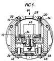
- the lower ends of the ball-screws 14 are journalled in sleeves 28 (Fig. 6) and the upper ends in bushes 30 in the bridge 26. Each ball-screw 14 passes through a nut 32 mounted in the platform 12.
- the cutter (not shown) is mounted on a sleeve 34 which is rotatably supported on the platform 12 by bearings 36.
- the cutter is also supported by a sleeve 38 in an aperture at the top of the bridge 26.
- the ball-screws 14 are rotated by an electric motor 40 which, through a gearbox 42, mounted on the base 20, drives a spur gear 44 which meshes with two spur gears 46. These in turn mesh with two further spur gears 48 fastened respectively on the ball-screws 14.
- the cutter is driven by two electric motors 50, 52, mounted on the platform 12 which jointly drive a spur gear 54 meshing with a spur gear 56 which surrounds, and is secured to, the sleeve 34.
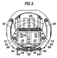
- each support leg 60, 62, 64 and 66 is pivotally mounted on one of the tie-bars 22, 24 and is secured to a cam 68 (which is also pivotally mounted on one of the tie-bars 22, 24).
- Each cam 68 is engaged by another respective cam 70 integral with the platform 12 (Fig. 1).
- FIG. 5 shows most clearly the form of the cams 68 and 70.
- the cam 70 may be called a first cam.
- the first cam 70 has a first nose 72 and a first surface 74.
- the cam 68 may be called a second cam.
- the second cam 68 has a second nose 76 and a second surface 78.
- Fig. 5 also shows the support legs 64 and 66, each of which also comprises a slave leg 80.
- the lower ends 82, 84 respectively of the legs 64 or 66 and the legs 80 are cranked and a compression spring 90 is located between the cranked ends.
- the spring 90 is pre-loaded to a pre-set compression.
- Each slave leg 80 is pivotally mounted on a tie-bar 22, 24.
- Fig. 4 shows the support legs 60, 62 each comprising a slave leg 80 as described above with reference to Figure 5.
- Fig. 4 also shows the first cams 70 each having a first nose 72 and a first surface 74 and also shows the second cams 68 each having a second nose 76 and a second surface 78.
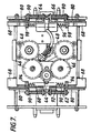
- Fig. 7 shows the two support legs 60 and 62 joined by a tension spring 92 which is pre-loaded to a pre-set tension and which has its ends anchored on pins 94 secured to the legs 60, 62.
- Fig. 7 also shows the support legs 64 and 66 joined by a tension spring 96, similar to the spring 92, and having its ends anchored on pins 98 secured to the legs 64 and 66.
- Fig. 7 shows that the cams 68 attached to the support legs 60 and 62 are wider than the cams 68 attached to the support legs 64 and 66.
- the wider cams 68 however merely act as spacers in order that the support legs 60, 62 can properly clear the base 20.
- the line of advance of the cutter is shown in Fig. 7 as being very close to the centre of the four points of engagement which the slave legs 80 would make with the pipeline in use.
- the body 10 is accurately positioned in the pipeline by accurately moving the train of modules within the pipeline.
- the pipeline contains a polyethylene liner and the body 10 is accurately positioned opposite an offtake opening in the pipeline.
- the cutter is then required to cut a hole in the plastic liner aligned with the offtake opening.
- a plastic service pipe is inserted in the existing service pipe connected to the offtake opening from the domestic dwelling or commercial building to which the service leads.
- the plastic pipe is subsequently joined to the plastic liner at the opening cut in it by the cutter.
- a completely new plastic pipe system is inserted within the existing service pipe.
- the platform 12 is advanced to bring the cutter into engagement with the plastic liner in the pipeline.
- the advance of the four cams 70 on the platform causes the faces 74 on the cams 70 to traverse past the noses 76 on the cams 68, forcing them to swing outwardly about the tie-bars 22, 24.
- the outward rotation of the cams 68 causes the outward rotation of the support legs 60, 62, 64 and 66 and the slave legs 80.
- the movement of the support legs stretches the return springs 92 (Fig. 7).
- the slave legs 80 come into contact with the inside wall surface (not shown) of the plastic liner.
- the noses 72 continue their traverse of the faces 78 and this produces continued outward movement of the support legs 60, 62, 64, 66.
- This continued movement of the support legs 60, 62, 64, 66 occurs while the slave legs 80 are prevented from further outward movement by the inside wall of the plastic liner.
- the continued movement of the support legs 60, 62, 64, 66 slightly compresses the compression springs 90.
- the apparatus is designed to be compatible with a range of internal diameters of the plastic liner.
- the pre-load in the springs 90 is sufficiently large to make slight differences in the degree of compression of the springs by the continued movement of the support legs 60, 62, 64, 66 just mentioned of no importance. the pre-load in the springs 90 is effectively the same whatever the precise position of the slave legs 80 is.
- the body 10 is completely supported by the slave legs 80 during the cutting operation.
Description
Claims (5)
- Apparatus for in-pipe use including a body (10) and a work-performing device which is advanceable and retractable relatively to said body (10) in a direction transverse to the length of said body (10), said apparatus comprising a mechanism (68, 70, 72, 74) which is actuated by the advance of said work-performing device to advance support means (60, 62, 64, 66, 80), said mechanism thereafter being effective to prevent retraction of said support means while allowing further advance of said work-performing device.
- Apparatus as claimed in Claim 1, in which said support means comprises two support legs on opposite sides of said direction.
- Apparatus as claimed in Claim 1, in which said support means comprises four support legs, two being on one side of said direction and two being on the opposite side of said direction.
- Apparatus as claimed in Claim 2 or Claim 3, in which said support leg in each case comprises a master leg advanceable by one of said mechanisms and a slave leg with a compression spring arranged between the master and slave legs, said slave leg leads said master leg during advance of the legs then, after said slave legs have engaged the inner surface of said pipe, said master leg continues to be advanced to compress said spring but said master leg does not advance as far as said slave leg.
- Apparatus as claimed in Claim 2, 3 or 4, in which said mechanism comprises for each said support leg a first cam having a first nose and a first surface and being movable relatively to said body with said work-performing device and a second cam fast with said support leg and which is pivotally connected to said body, said second cam has a second nose and a second surface, and advancing movement of said first cam with its first surface engages said nose of said second cam causing said second cam to swing outwardly relatively to said body taking said support leg with it, then continued advancing movement of said first cam with its nose engaging said second surface of said second cam prevents retraction of said second cam.
Applications Claiming Priority (3)
| Application Number | Priority Date | Filing Date | Title |
|---|---|---|---|
| GB9511908 | 1995-06-12 | ||
| GBGB9511908.7A GB9511908D0 (en) | 1995-06-12 | 1995-06-12 | Apparatus for in-pipe use |
| PCT/GB1996/001389 WO1996041694A1 (en) | 1995-06-12 | 1996-06-10 | Apparatus for in-pipe use |
Publications (2)
| Publication Number | Publication Date |
|---|---|
| EP0961667A1 EP0961667A1 (en) | 1999-12-08 |
| EP0961667B1 true EP0961667B1 (en) | 2001-11-14 |
Family
ID=10775929
Family Applications (1)
| Application Number | Title | Priority Date | Filing Date |
|---|---|---|---|
| EP96917585A Expired - Lifetime EP0961667B1 (en) | 1995-06-12 | 1996-06-10 | Apparatus for in-pipe use |
Country Status (8)
| Country | Link |
|---|---|
| US (1) | US5951221A (en) |
| EP (1) | EP0961667B1 (en) |
| AR (1) | AR002434A1 (en) |
| CA (1) | CA2223840C (en) |
| DE (1) | DE69617057T2 (en) |
| ES (1) | ES2168477T3 (en) |
| GB (2) | GB9511908D0 (en) |
| WO (1) | WO1996041694A1 (en) |
Families Citing this family (1)
| Publication number | Priority date | Publication date | Assignee | Title |
|---|---|---|---|---|
| US6599067B2 (en) * | 2001-03-26 | 2003-07-29 | Atomic Energy Of Canada Limited | Apparatus for removing pressure tubes |
Family Cites Families (9)
| Publication number | Priority date | Publication date | Assignee | Title |
|---|---|---|---|---|
| GB2119296B (en) * | 1982-03-29 | 1986-03-26 | Ian Roland Yarnell | Remote-control travelling robot for performing operations eg cutting within a pipe |
| US4708279A (en) * | 1984-05-14 | 1987-11-24 | Dearman Timothy Charles | Internal alignment clamp |
| EP0204694B1 (en) * | 1984-12-14 | 1989-07-05 | Kunststoff-Technik AG Himmler | Device for carrying out improvement work on a damaged pipeline which is no longer accessible |
| US5197540A (en) * | 1987-04-14 | 1993-03-30 | Ashimori Kogyo Kabushiki Kaisha | Boring device for lining material in branched portions of lined conduit |
| DE68906273T2 (en) * | 1988-01-27 | 1993-09-16 | Iseki Kaihatsu Koki | DEVICE FOR CARRYING OUT WORK IN A PIPE. |
| US5105882A (en) * | 1990-01-25 | 1992-04-21 | Trb Specialty Rehabilitation, Inc. | Lateral cutter device |
| US5088553A (en) * | 1990-01-25 | 1992-02-18 | Trb Specialty Rehabilitation, Inc. | Lateral cutter device |
| US5286144A (en) * | 1991-08-05 | 1994-02-15 | Griner Ward J | Apparatus and method for cutting a hole in a pipe liner |
| DE19515927C1 (en) * | 1995-05-02 | 1996-08-29 | D T I Dr Trippe Ingenieurgesel | Working device operating internally on pipelines or channels |
-
1995
- 1995-06-12 GB GBGB9511908.7A patent/GB9511908D0/en active Pending
-
1996
- 1996-06-10 WO PCT/GB1996/001389 patent/WO1996041694A1/en active IP Right Grant
- 1996-06-10 DE DE69617057T patent/DE69617057T2/en not_active Expired - Fee Related
- 1996-06-10 GB GB9612066A patent/GB2302155B/en not_active Expired - Fee Related
- 1996-06-10 ES ES96917585T patent/ES2168477T3/en not_active Expired - Lifetime
- 1996-06-10 US US08/983,062 patent/US5951221A/en not_active Expired - Fee Related
- 1996-06-10 CA CA002223840A patent/CA2223840C/en not_active Expired - Fee Related
- 1996-06-10 EP EP96917585A patent/EP0961667B1/en not_active Expired - Lifetime
- 1996-06-11 AR ARP960103101A patent/AR002434A1/en unknown
Also Published As
| Publication number | Publication date |
|---|---|
| AR002434A1 (en) | 1998-03-11 |
| GB2302155B (en) | 1998-08-26 |
| CA2223840A1 (en) | 1996-12-27 |
| DE69617057T2 (en) | 2002-06-27 |
| DE69617057D1 (en) | 2001-12-20 |
| US5951221A (en) | 1999-09-14 |
| WO1996041694A1 (en) | 1996-12-27 |
| CA2223840C (en) | 2002-02-19 |
| EP0961667A1 (en) | 1999-12-08 |
| GB2302155A (en) | 1997-01-08 |
| GB9511908D0 (en) | 1995-08-09 |
| ES2168477T3 (en) | 2002-06-16 |
| GB9612066D0 (en) | 1996-08-14 |
Similar Documents
| Publication | Publication Date | Title |
|---|---|---|
| US5368423A (en) | Robotic cutter | |
| KR920008489B1 (en) | Boring apparatus | |
| US5167173A (en) | Tong | |
| US6065212A (en) | Powered tube cutter and cutting process | |
| US5477759A (en) | Radial cutting tool for cutting thick-walled tubular members | |
| DE2727169A1 (en) | MANIPULATOR | |
| US5603250A (en) | Radial cutting tool having indexed pair of bit-subassemblies with simultaneous feed for cutting thick-walled tubes | |
| US20040031940A1 (en) | Blowout valve assembly | |
| US7223054B1 (en) | Spiral groove pipe joint machining assembly | |
| CN112338505B (en) | Pipe column connecting and disassembling device | |
| US5557995A (en) | Radial cutting tools for cutting thick-walled tubular members | |
| EP0961667B1 (en) | Apparatus for in-pipe use | |
| EP2158998B1 (en) | Tool revolver | |
| US5009007A (en) | Window cutter for gas service tie overs | |
| WO2011108939A1 (en) | Device for remote-controlled, submarine machining unit | |
| CH672895A5 (en) | ||
| WO1998026153A1 (en) | Apparatus for connecting and disconnecting drill rods | |
| KR102175173B1 (en) | Apparatus for cutting seat ring of power plant valve | |
| DE102006016232A1 (en) | Machining assembly for non-rotating pipe-end has external orbit cutting tool and inner tool mounted on rod with combined clamp and cutter | |
| US6460434B2 (en) | Machining assembly and a method | |
| KR100488238B1 (en) | Processing device of pipe hole | |
| JP3504787B2 (en) | Pipe cutting device | |
| KR102205500B1 (en) | Spindle device for seat ring cutter of power plant valves | |
| JP4262567B2 (en) | Continuous water valve insertion method | |
| JPH06226547A (en) | Pipe cutting device |
Legal Events
| Date | Code | Title | Description |
|---|---|---|---|
| PUAI | Public reference made under article 153(3) epc to a published international application that has entered the european phase |
Free format text: ORIGINAL CODE: 0009012 |
|
| 17P | Request for examination filed |
Effective date: 19980407 |
|
| AK | Designated contracting states |
Kind code of ref document: A1 Designated state(s): BE DE ES FR GB IT NL SE |
|
| GRAG | Despatch of communication of intention to grant |
Free format text: ORIGINAL CODE: EPIDOS AGRA |
|
| 17Q | First examination report despatched |
Effective date: 20000815 |
|
| GRAG | Despatch of communication of intention to grant |
Free format text: ORIGINAL CODE: EPIDOS AGRA |
|
| GRAH | Despatch of communication of intention to grant a patent |
Free format text: ORIGINAL CODE: EPIDOS IGRA |
|
| GRAH | Despatch of communication of intention to grant a patent |
Free format text: ORIGINAL CODE: EPIDOS IGRA |
|
| RAP1 | Party data changed (applicant data changed or rights of an application transferred) |
Owner name: LATTICE INTELLECTUAL PROPERTY LIMITED |
|
| GRAA | (expected) grant |
Free format text: ORIGINAL CODE: 0009210 |
|
| AK | Designated contracting states |
Kind code of ref document: B1 Designated state(s): BE DE ES FR GB IT NL SE |
|
| REF | Corresponds to: |
Ref document number: 69617057 Country of ref document: DE Date of ref document: 20011220 |
|
| REG | Reference to a national code |
Ref country code: GB Ref legal event code: IF02 |
|
| ET | Fr: translation filed | ||
| REG | Reference to a national code |
Ref country code: ES Ref legal event code: FG2A Ref document number: 2168477 Country of ref document: ES Kind code of ref document: T3 |
|
| PLBE | No opposition filed within time limit |
Free format text: ORIGINAL CODE: 0009261 |
|
| STAA | Information on the status of an ep patent application or granted ep patent |
Free format text: STATUS: NO OPPOSITION FILED WITHIN TIME LIMIT |
|
| 26N | No opposition filed | ||
| PGFP | Annual fee paid to national office [announced via postgrant information from national office to epo] |
Ref country code: FR Payment date: 20040513 Year of fee payment: 9 |
|
| PGFP | Annual fee paid to national office [announced via postgrant information from national office to epo] |
Ref country code: NL Payment date: 20040514 Year of fee payment: 9 |
|
| PGFP | Annual fee paid to national office [announced via postgrant information from national office to epo] |
Ref country code: GB Payment date: 20040517 Year of fee payment: 9 |
|
| PGFP | Annual fee paid to national office [announced via postgrant information from national office to epo] |
Ref country code: DE Payment date: 20040520 Year of fee payment: 9 |
|
| PGFP | Annual fee paid to national office [announced via postgrant information from national office to epo] |
Ref country code: SE Payment date: 20040521 Year of fee payment: 9 |
|
| PGFP | Annual fee paid to national office [announced via postgrant information from national office to epo] |
Ref country code: ES Payment date: 20040607 Year of fee payment: 9 |
|
| PGFP | Annual fee paid to national office [announced via postgrant information from national office to epo] |
Ref country code: BE Payment date: 20040616 Year of fee payment: 9 |
|
| PG25 | Lapsed in a contracting state [announced via postgrant information from national office to epo] |
Ref country code: IT Free format text: LAPSE BECAUSE OF NON-PAYMENT OF DUE FEES Effective date: 20050610 Ref country code: GB Free format text: LAPSE BECAUSE OF NON-PAYMENT OF DUE FEES Effective date: 20050610 |
|
| PG25 | Lapsed in a contracting state [announced via postgrant information from national office to epo] |
Ref country code: SE Free format text: LAPSE BECAUSE OF NON-PAYMENT OF DUE FEES Effective date: 20050611 Ref country code: ES Free format text: LAPSE BECAUSE OF NON-PAYMENT OF DUE FEES Effective date: 20050611 |
|
| PG25 | Lapsed in a contracting state [announced via postgrant information from national office to epo] |
Ref country code: BE Free format text: LAPSE BECAUSE OF NON-PAYMENT OF DUE FEES Effective date: 20050630 |
|
| PG25 | Lapsed in a contracting state [announced via postgrant information from national office to epo] |
Ref country code: NL Free format text: LAPSE BECAUSE OF NON-PAYMENT OF DUE FEES Effective date: 20060101 |
|
| PG25 | Lapsed in a contracting state [announced via postgrant information from national office to epo] |
Ref country code: DE Free format text: LAPSE BECAUSE OF NON-PAYMENT OF DUE FEES Effective date: 20060103 |
|
| EUG | Se: european patent has lapsed | ||
| PG25 | Lapsed in a contracting state [announced via postgrant information from national office to epo] |
Ref country code: FR Free format text: LAPSE BECAUSE OF NON-PAYMENT OF DUE FEES Effective date: 20060228 |
|
| GBPC | Gb: european patent ceased through non-payment of renewal fee |
Effective date: 20050610 |
|
| NLV4 | Nl: lapsed or anulled due to non-payment of the annual fee |
Effective date: 20060101 |
|
| REG | Reference to a national code |
Ref country code: FR Ref legal event code: ST Effective date: 20060228 |
|
| REG | Reference to a national code |
Ref country code: ES Ref legal event code: FD2A Effective date: 20050611 |
|
| BERE | Be: lapsed |
Owner name: *LATTICE INTELLECTUAL PROPERTY LTD Effective date: 20050630 |