EP0961393A1 - Linear motor for textile machine, device with a linear motor and Loom with this device - Google Patents
Linear motor for textile machine, device with a linear motor and Loom with this device Download PDFInfo
- Publication number
- EP0961393A1 EP0961393A1 EP98810495A EP98810495A EP0961393A1 EP 0961393 A1 EP0961393 A1 EP 0961393A1 EP 98810495 A EP98810495 A EP 98810495A EP 98810495 A EP98810495 A EP 98810495A EP 0961393 A1 EP0961393 A1 EP 0961393A1
- Authority
- EP
- European Patent Office
- Prior art keywords
- stator
- armature
- linear motor
- coil
- motor according
- Prior art date
- Legal status (The legal status is an assumption and is not a legal conclusion. Google has not performed a legal analysis and makes no representation as to the accuracy of the status listed.)
- Withdrawn
Links
- 239000004753 textile Substances 0.000 title claims abstract description 6
- 239000003302 ferromagnetic material Substances 0.000 claims abstract description 9
- RYGMFSIKBFXOCR-UHFFFAOYSA-N Copper Chemical compound [Cu] RYGMFSIKBFXOCR-UHFFFAOYSA-N 0.000 claims abstract description 7
- 229910052802 copper Inorganic materials 0.000 claims abstract description 7
- 239000010949 copper Substances 0.000 claims abstract description 7
- 230000005291 magnetic effect Effects 0.000 claims abstract description 6
- 238000009941 weaving Methods 0.000 claims description 7
- 238000013016 damping Methods 0.000 claims description 3
- 230000005294 ferromagnetic effect Effects 0.000 claims description 2
- 239000011248 coating agent Substances 0.000 claims 1
- 238000000576 coating method Methods 0.000 claims 1
- 238000009434 installation Methods 0.000 claims 1
- 239000000463 material Substances 0.000 claims 1
- 210000000056 organ Anatomy 0.000 claims 1
- 238000005253 cladding Methods 0.000 abstract 1
- XAGFODPZIPBFFR-UHFFFAOYSA-N aluminium Chemical compound [Al] XAGFODPZIPBFFR-UHFFFAOYSA-N 0.000 description 2
- 229910052782 aluminium Inorganic materials 0.000 description 2
- 125000006850 spacer group Chemical group 0.000 description 2
- 230000001133 acceleration Effects 0.000 description 1
- 239000004020 conductor Substances 0.000 description 1
- 230000000694 effects Effects 0.000 description 1
- 238000003780 insertion Methods 0.000 description 1
- 230000037431 insertion Effects 0.000 description 1
- 230000000750 progressive effect Effects 0.000 description 1
- 239000000725 suspension Substances 0.000 description 1
- 238000004804 winding Methods 0.000 description 1
Images


Classifications
-
- H—ELECTRICITY
- H02—GENERATION; CONVERSION OR DISTRIBUTION OF ELECTRIC POWER
- H02K—DYNAMO-ELECTRIC MACHINES
- H02K41/00—Propulsion systems in which a rigid body is moved along a path due to dynamo-electric interaction between the body and a magnetic field travelling along the path
- H02K41/02—Linear motors; Sectional motors
- H02K41/035—DC motors; Unipolar motors
- H02K41/0352—Unipolar motors
- H02K41/0354—Lorentz force motors, e.g. voice coil motors
-
- B—PERFORMING OPERATIONS; TRANSPORTING
- B65—CONVEYING; PACKING; STORING; HANDLING THIN OR FILAMENTARY MATERIAL
- B65H—HANDLING THIN OR FILAMENTARY MATERIAL, e.g. SHEETS, WEBS, CABLES
- B65H59/00—Adjusting or controlling tension in filamentary material, e.g. for preventing snarling; Applications of tension indicators
- B65H59/10—Adjusting or controlling tension in filamentary material, e.g. for preventing snarling; Applications of tension indicators by devices acting on running material and not associated with supply or take-up devices
- B65H59/20—Co-operating surfaces mounted for relative movement
- B65H59/22—Co-operating surfaces mounted for relative movement and arranged to apply pressure to material
-
- D—TEXTILES; PAPER
- D03—WEAVING
- D03D—WOVEN FABRICS; METHODS OF WEAVING; LOOMS
- D03D47/00—Looms in which bulk supply of weft does not pass through shed, e.g. shuttleless looms, gripper shuttle looms, dummy shuttle looms
- D03D47/34—Handling the weft between bulk storage and weft-inserting means
- D03D47/36—Measuring and cutting the weft
- D03D47/361—Drum-type weft feeding devices
- D03D47/364—Yarn braking means acting on the drum
-
- B—PERFORMING OPERATIONS; TRANSPORTING
- B65—CONVEYING; PACKING; STORING; HANDLING THIN OR FILAMENTARY MATERIAL
- B65H—HANDLING THIN OR FILAMENTARY MATERIAL, e.g. SHEETS, WEBS, CABLES
- B65H2555/00—Actuating means
- B65H2555/10—Actuating means linear
- B65H2555/13—Actuating means linear magnetic, e.g. induction motors
-
- B—PERFORMING OPERATIONS; TRANSPORTING
- B65—CONVEYING; PACKING; STORING; HANDLING THIN OR FILAMENTARY MATERIAL
- B65H—HANDLING THIN OR FILAMENTARY MATERIAL, e.g. SHEETS, WEBS, CABLES
- B65H2601/00—Problem to be solved or advantage achieved
- B65H2601/50—Diminishing, minimizing or reducing
- B65H2601/52—Diminishing, minimizing or reducing entities relating to handling machine
- B65H2601/524—Vibration
-
- B—PERFORMING OPERATIONS; TRANSPORTING
- B65—CONVEYING; PACKING; STORING; HANDLING THIN OR FILAMENTARY MATERIAL
- B65H—HANDLING THIN OR FILAMENTARY MATERIAL, e.g. SHEETS, WEBS, CABLES
- B65H2701/00—Handled material; Storage means
- B65H2701/30—Handled filamentary material
- B65H2701/31—Textiles threads or artificial strands of filaments
-
- H—ELECTRICITY
- H02—GENERATION; CONVERSION OR DISTRIBUTION OF ELECTRIC POWER
- H02K—DYNAMO-ELECTRIC MACHINES
- H02K2201/00—Specific aspects not provided for in the other groups of this subclass relating to the magnetic circuits
- H02K2201/18—Machines moving with multiple degrees of freedom
Definitions
- the invention relates to a linear motor for a Textile machine according to the preamble of claim 1 and a device for influencing a Sequence of movements of a thread with a linear motor and a weaving machine with such a device.
- US-A-4,998,420 is a linear motor for one Weaving machine described a stator with a ferromagnetic plate and a permanent magnet with different polarity as well as an anchor with a Has winding.
- the stator is stationary and the anchor can be rotated on a fixed axis stored.
- the invention is based on the object Improve linear motor.
- the side walls of the bobbin can on the Be provided with a copper layer on the outside or be made of aluminum. This has the advantage that the permanent magnet or the pair of magnets in the Copper layer creates eddy currents which cause the movement dampen the anchor.
- a device for influencing the movement at least one thread or ribbon with a linear motor is according to the invention by the features of claim 8 featured.
- This is a weaving machine with a device characterized in that the device as a thread brake in Path of the weft thread is arranged.
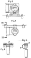
- FIGS. 1 and 2 Of the Linear motor has a stator 1, an armature 2 and two Leaf springs 3, which as bearing parts for the anchor to serve.
- the stator contains two plates 5 ferromagnetic material, two spacers 6, 7 which connect the plates and keep them at a distance and two permanent magnet pairs 8 with different Polarity attached to the inside of the plates are.
- the armature 2 contains a coil former 9 with a Core 10 and two side walls 11 from one not ferromagnetic material, e.g. Plastic; a coil 12 and a first connecting member 13 and a second Connecting member 14.
- the side walls 11 of the bobbin are provided with a copper layer or made of aluminum are manufactured.
- the leaf springs are each on one End at spacer 7 and at the other end at Connection member 13, 14 attached.
- the leaf springs 3 have connections, not shown, for the power supply on and are with the connecting wires of the coil connected. With this arrangement, a safe Power supply to the coil guaranteed.
- the linear motor between the Bearing parts 3 arranged. But it is also possible Arrange the linear motor outside the bearing parts.
- FIG. 3 shows another embodiment of a Linear motor.
- the armature 2 is by means of Handlebar 15 mounted on the stator 1.
- a guide member 16 arranged to anchor 2 during the movement on the parallel aligned plates of the Lead stator free of play.
- the thread brake contains a stationary one Brake part 22 and a movable brake body 23.
- the Fixed brake part 22 is designed as a brake band and flexibly arranged in holders 24.
- the mobile Brake body 23 is connected to armature 2.
- the Thread brake is connected to the linear motor and by means of elastic members 25 attached to a loom to the vibrations occurring on the machine frame dampen.
- FIG. 6 shows an embodiment of a thread brake two brake bodies, so that a thread in two places is braked. This can on the one hand reinforce the Braking effect can be achieved on the other hand can the specific braking load on the thread be distributed.
- FIGS. 7 to 9. show a thread brake for two in parallel running threads with only one linear motor, however the brake body 23 is T-shaped and on the arranged below, aligned in parallel Thread brakes act.
- 9 shows a thread brake for a thread, the brake body hook-shaped is designed to symmetrically apply the braking force to the To direct the braking part. To insert a thread in The thread brake is easier with these Designs of the linear motor below the brake band arranged.
- the brake body is by means of a bracket 29 connected to the armature of the linear motor.
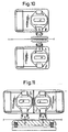
- Figures 10 to 11 show versions of Thread brakes with two each independently controllable linear motors. With these designs there are further possibilities for one Brake booster and on the other hand distribution of specific braking load on the thread. Can also the response times for e.g. a phased braking of the Thread run shortened by alternating loading become.
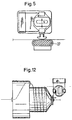
- FIG 12 shows an application of the linear motor in FIG Connection with one, on the thread take-off side of a Thread store arranged known plate thread brake.
- the movable brake actuator is on one extended bearing part of the linear motor attached.
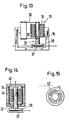
- the 13 shows a linear motor which has a stator 31, contains an anchor 32 and two bearing parts 33.
- the stator includes a coil 34 provided in a housing 35 is.
- the armature 32 is a permanent magnet attached to the Bearing parts 33 is attached.
- the bearing parts are as Leaf springs trained.
- This linear motor is part shown a thread brake, which also has a holder 36, a stationary brake part 37 and a brake body 38 has.
- the linear motor and the stationary braking part are arranged on the holder and the brake body is on Anchors attached.
- FIG. 14 shows a fourth embodiment of a Linear motor, which is essentially the same as that Linear motor is designed according to Fig. 13.
- the bearing parts are designed as ring springs and e.g. at the same time power connection conductor for the coil educated.
- the thread to be braked can be in full Line shown shape between the braking members 37, 38 be passed through, or radially to the center this to axially through a central bore, not shown to be led.
- FIGS. 16 to 19 The Fig. 16 shows a device for controllable conveying a thread or ribbon with a linear motor.
- the device contains a conveyor roller 51, which of a Drive, not shown, is rotated and a pressure roller 52 connected to the linear motor is, wherein a friction entrainment is generated.
- a friction entrainment is generated.
- this device can instead of the double deflection simple redirection can be applied.
- FIG. 17 shows a device for acceleration of a thread with a linear motor.
- This device includes a conveyor roller 53 driven by a motor (not shown) is driven and preferably also driven pressure roller 54, which with the Linear motor is connected.
- This device can e.g. to accelerate a weft to avoid it the so-called stretch stroke when weft insertion in a projectile weaving machine as well as to support the Weft entries are used in air weaving machines.
- FIG. 18 shows a device for deflecting a Thread, e.g. controllable damping at the end of Weft entry at e.g. To achieve air weaving machines.
- the linear motor contains a stator 1, the one Magnetic field creates an armature 2, which is in the magnetic field is arranged and two flexible bearing parts 3, the are arranged parallel to each other so that the one with the Bearing parts connected armature movable relative to the stator is.
Abstract
Description
Die Erfindung betrifft einen Linearmotor für eine Textilmaschine gemäss dem Oberbegriff des Anspruches 1 sowie eine vorrichtung zur Beeinflussung eines Bewegungsablaufes eines Fadens mit einem Linearmotor und eine Webmaschine mit einer solchen Vorrichtung.The invention relates to a linear motor for a Textile machine according to the preamble of claim 1 and a device for influencing a Sequence of movements of a thread with a linear motor and a weaving machine with such a device.
In der US-A-4,998,420 ist ein Linearmotor für eine Webmaschine beschrieben, der einen Stator mit einer ferromagnetischen Platte und einem Permanentmagnet mit unterschiedlicher Polarität sowie einen Anker mit einer Wicklung aufweist. Der Stator ist ortsfest angeordnet und der Anker ist auf einer ortsfesten Achse drehbar gelagert.In US-A-4,998,420 is a linear motor for one Weaving machine described a stator with a ferromagnetic plate and a permanent magnet with different polarity as well as an anchor with a Has winding. The stator is stationary and the anchor can be rotated on a fixed axis stored.
Bei dieser Ausführung des Linearmotors erweist sich die auftretende Lagerreibung als auch das Lagerspiel als Nachteil.This version of the linear motor proves that bearing friction occurring as well as the bearing play as Disadvantage.
Der Erfindung liegt die Aufgabe zugrunde einen Linearmotor zu verbessern.The invention is based on the object Improve linear motor.
Diese Aufgabe wird erfindungsgemäss mit den Merkmalen des Anspruches 1 gelöst. This object is achieved with the features of Claim 1 solved.
Die mit der Erfindung erzielbaren Vorteile sind im Wesentlichen darin zu sehen, dass der Anker eine Bewegung in einer Ebene ausführt, dass die Bewegung hysteresefrei und in den Lagern absolut spielfrei ist und dass die vom Anker ausgeübte Kraft direkt proportional zur Stromstärke ist.The advantages achievable with the invention are in Essentially seen in the fact that the anchor is a movement executes in a plane that the movement is free of hysteresis and is absolutely free of play in the camps and that from Armature force directly proportional to the current is.
Die Seitenwände des Spulenkörpers können an der Aussenseite mit einer Kupferschicht versehen werden oder aus Aluminium hergestellt sein. Dies hat den Vorteil, dass der Permanentmagnet bzw. das Magnetpaar in der Kupferschicht Wirbelströme erzeugt, welche die Bewegung des Ankers dämpfen.The side walls of the bobbin can on the Be provided with a copper layer on the outside or be made of aluminum. This has the advantage that the permanent magnet or the pair of magnets in the Copper layer creates eddy currents which cause the movement dampen the anchor.
Eine Vorrichtung zur Beeinflussung des Bewegungsablaufes
mindestens eines Fadens oder Bandes mit einem Linearmotor
ist erfindungsgemäss durch die Merkmale des Anspruches 8
gekennzeichnet.A device for influencing the movement
at least one thread or ribbon with a linear motor
is according to the invention by the features of
Der Vorteil dieser Vorrichtung ist in der Vielzahl der Anwendungen in Textilmaschinen zu sehen.The advantage of this device is in the variety of See applications in textile machines.
Eine Webmaschine mit einer Vorrichtung ist dadurch gekennzeichnet, dass die Vorrichtung als Fadenbremse im Laufweg des Schussfadens angeordnet ist.This is a weaving machine with a device characterized in that the device as a thread brake in Path of the weft thread is arranged.
Nachfolgend wird die Erfindung anhand der beiliegenden Zeichnungen erläutert.The invention is described below with reference to the enclosed Drawings explained.
Es zeigen:
- Fig. 1 und 2
- Eine Ausführungsform eines erfindungsgemässen Linearmotors im Schnitt;
- Fig. 3
- eine schematische Darstellung einer zweiten Ausführungsform eines Linearmotors;
- Fig. 4
- eine erste Ausführungsform einer erfindungsgemässen Vorrichtung;
- Fig. 5
- eine zweite Ausführungsform einer erfindungsgemässen Vorrichtung in schematischer Darstellung;
- Fig. 6
- eine dritte Ausführungsform einer Vorrichtung in schematischer Darstellung;
- Fig. 7
- eine vierte Ausführungsform einer Vorrichtung in schematischer Darstellung;
- Fig. 8
- ein Schnitt entlang der Linie VIII-VIII in Fig. 7;
- Fig. 9
- eine fünfte Ausführungsform einer Vorrichtung in schematischer Darstellung;
- Fig. 10
- eine sechste Ausführungsform einer Vorrichtung in schematischer Darstellung;
- Fig. 11
- eine siebente Ausführungsform einer vorrichtung in schematischer Darstellung;
- Fig. 12
- eine achte Ausführungsform einer vorrichtung in schematischer Darstellung;
- Fig. 13
- eine dritte Ausführungsform eines erfindungsgemässen Linearmotors als Teil einer Fadenbremse im Schnitt;
- Fig. 14
- eine vierte Ausführungsform eines erfindungsgemässen Linearmotors als Teil einer Fadenbremse im Schnitt;
- Fig. 15
- eine Ausführungsform einer Feder im Linearmotor gemäss Fig. 14;
- Fig. 16
- eine zehnte Ausführungsform einer vorrichtung in schematischer Darstellung;
- Fig. 17
- eine elfte Ausführungsform einer Vorrichtung in schematischer Darstellung;
- Fig. 18
- eine zwölfte Ausführungsform einer Vorrichtung in schematischer Darstellung und
- Fig. 19
- eine fünfte Ausführungsform eines Linearmotors als Teil einer Fadenbremse im Schnitt.
- 1 and 2
- An embodiment of a linear motor according to the invention in section;
- Fig. 3
- a schematic representation of a second embodiment of a linear motor;
- Fig. 4
- a first embodiment of a device according to the invention;
- Fig. 5
- a second embodiment of a device according to the invention in a schematic representation;
- Fig. 6
- a third embodiment of a device in a schematic representation;
- Fig. 7
- a fourth embodiment of a device in a schematic representation;
- Fig. 8
- a section along the line VIII-VIII in Fig. 7;
- Fig. 9
- a fifth embodiment of a device in a schematic representation;
- Fig. 10
- a sixth embodiment of a device in a schematic representation;
- Fig. 11
- a seventh embodiment of a device in a schematic representation;
- Fig. 12
- an eighth embodiment of a device in a schematic representation;
- Fig. 13
- a third embodiment of a linear motor according to the invention as part of a thread brake in section;
- Fig. 14
- a fourth embodiment of a linear motor according to the invention as part of a thread brake in section;
- Fig. 15
- an embodiment of a spring in the linear motor according to FIG. 14;
- Fig. 16
- a tenth embodiment of a device in a schematic representation;
- Fig. 17
- an eleventh embodiment of a device in a schematic representation;
- Fig. 18
- a twelfth embodiment of a device in a schematic representation and
- Fig. 19
- a fifth embodiment of a linear motor as part of a thread brake in section.
Es wird auf die Figuren 1 und 2 Bezug genommen. Der
Linearmotor weist einen Stator 1, einen Anker 2 und zwei
Blattfedern 3 auf, welche als Lagerteile für den Anker
dienen. Der Stator enthält zwei Platten 5 aus
ferromagnetischen Material, zwei Abstandsstücke 6, 7
welche die Platten verbinden und auf Abstand halten und
zwei Permanentmagnetpaare 8 mit unterschiedlicher
Polarität, die auf der Innenseite der Platten befestigt
sind. Der Anker 2 enthält einen Spulenkörper 9 mit einem
Kern 10 und zwei Seitenwänden 11 aus einem nicht
ferromagnetischen Material, z.B. Kunststoff; eine spule
12 sowie ein erstes Verbindungsorgan 13 und ein zweites
Verbindungsorgan 14. Die Seitenwände 11 des Spulenkörpers
sind mit einer Kupferschicht versehen oder aus Aluminium
hergestellt sind. Die Blattfedern sind jeweils an einem
Ende am Abstandsstück 7 und am anderen Ende am
Verbindungsorgan 13, 14 befestigt. Die Blattfedern 3
weisen nicht dargestellte Anschlüsse für die Stromzufuhr
auf und sind mit den Anschlussdrähten der Spule
verbunden. Mit dieser Anordnung wird eine sichere
Stromzufuhr zur Spule gewährleistet. Bei der vorstehend
beschriebenen Ausführung ist der Linearmotor zwischen den
Lagerteilen 3 angeordnet. Es ist aber auch möglich den
Linearmotor ausserhalb der Lagerteile anzuordnen.Reference is made to FIGS. 1 and 2. Of the
Linear motor has a stator 1, an
Die Funktionsweise eines Linearmotors ist bekannt und
wird daher nicht näher erläutert. Bei erregter Spule wird
der Anker 2 ausgelenkt, wobei durch die Blattfedern 3 der
Anker 2 eine Bewegung in einer Ebene ausführt. Dadurch,
dass, die Seitenwände des Spulenkörpers an den aussen und
den Permanentmagnetpaaren gegenüber liegenden Flächen mit
z.B. einer Kupferschicht versehen sind, werden während
des Betriebes Wirbelströme in der Kupferschicht erzeugt,
welche die Bewegung des Ankers 2 dämpfen.The operation of a linear motor is known and
is therefore not explained in more detail. When the coil is excited
the
Durch die parallele Ausrichtung der Lagerteile zueinander ist es möglich, einen extrem kleinen Luftspalt zwischen Anker und Stator vorzusehen. Indem einseitig fest verankerte Blattfedern als Lagerteile verwendet werden, ergibt sich eine absolut spielfreie Lagerung. Due to the parallel alignment of the bearing parts to each other it is possible to have an extremely small air gap between Provide armature and stator. By stuck on one side anchored leaf springs are used as bearing parts, there is absolutely no play.
Die Fig. 3 zeigt eine andere Ausführung eines
Linearmotors. Bei diesem Motor ist der Anker 2 mittels
Lenker 15 am Stator 1 gelagert. An den Hebeln ist jeweils
ein Führungsteil 16 angeordnet, um den Anker 2 während
der Bewegung an den parallel ausgerichteten Platten des
Stators spielfrei zu führen. Es kann eine Feder 17, um
bei abgeschalteten bzw. umgepoltenen Motor den Anker 2 in
die Grundstellung zurückzustellen und ein elastischer
Teil 18 vorgesehen werden, um eine Dämpfung durch einen
weicheren Anschlag zu erzielen.3 shows another embodiment of a
Linear motor. In this engine, the
Die Fig. 4 zeigt eine Fadenbremse 21 mit einem
Linearmotor. Die Fadenbremse enthält einen ortsfesten
Bremsteil 22 und einen beweglichen Bremskörper 23. Der
ortsfeste Bremsteil 22 ist als Bremsband ausgebildet und
nachgiebig in Haltern 24 angeordnet. Der bewegliche
Bremskörper 23 ist mit dem Anker 2 verbunden. Die
Fadenbremse ist mit dem Linearmotor verbunden und mittels
elastische Elemente 25 an einer Webmaschine befestigt, um
die am Maschinengestell auftretenden Schwingungen zu
dämpfen.4 shows a
Bei der in Fig. 5 gezeigten Ausführung der Fadenbremse
ist am ortsfesten Bremsteil ein elastischer Körper 27
befestigt, um eine progressive Federung zu erzielen.In the embodiment of the thread brake shown in FIG. 5
is an
Die Fig. 6 zeigt eine Ausführung einer Fadenbremse mit zwei Bremskörper, so dass ein Faden an zwei stellen gebremst wird. Damit kann einerseits eine Verstärkung der Bremswirkung auf den Faden erzielt werden, anderseits kann die spezifische Bremsbelastung auf den Faden verteilt werden.6 shows an embodiment of a thread brake two brake bodies, so that a thread in two places is braked. This can on the one hand reinforce the Braking effect can be achieved on the other hand can the specific braking load on the thread be distributed.
Es wird auf die Figuren 7 bis 9 Bezug genommen. Die
Figuren 7 und 8 zeigen eine Fadenbremse für zwei parallel
verlaufende Fäden mit jedoch nur einem Linearmotor, wobei
der Bremskörper 23 T-förmig ausgebildet ist und auf die
darunter angeordneten, parallel ausgerichteten
Fadenbremsen einwirkt. Die Fig. 9 zeigt eine Fadenbremse
für einen Faden, wobei der Bremskörper hakenförmig
ausgebildet ist, um die Bremskraft symmetrisch auf das
Bremsteil zu richten. Um das Einführen eines Fadens in
die Fadenbremse zu erleichtern, ist bei diesen
Ausführungen der Linearmotor unterhalb des Bremsbandes
angeordnet. Der Bremskörper ist mittels eines Bügels 29
mit dem Anker des Linearmotors verbunden.Reference is made to FIGS. 7 to 9. The
Figures 7 and 8 show a thread brake for two in parallel
running threads with only one linear motor, however
the
Die Figuren 10 bis 11 zeigen Ausführungen von Fadenbremsen mit jeweils zwei, voneinander unabhängig steuerbaren Linearmotoren. Mit diesen Ausführungen ergeben sich weitere Möglichkeiten für einerseits eine Bremskraftverstärkung und andererseits Aufteilung der spezifischen Bremsbelastung auf den Faden. Ferner können die Reaktionszeiten für z.B. ein phasenweises Bremsen des Fadenlaufes durch wechselweise Beaufschlagung verkürzt werden.Figures 10 to 11 show versions of Thread brakes with two each independently controllable linear motors. With these designs there are further possibilities for one Brake booster and on the other hand distribution of specific braking load on the thread. Can also the response times for e.g. a phased braking of the Thread run shortened by alternating loading become.
Fig. 12 zeigt eine Anwendung des Linearmotors in Verbindung mit einer, an der Fadenabzugsseite eines Fadenspeichers angeordneten bekannten Tellerfadenbremse. Hierbei ist der bewegliche Bremsteller an einem verlängerten Lagerteil des Linearmotors befestigt.12 shows an application of the linear motor in FIG Connection with one, on the thread take-off side of a Thread store arranged known plate thread brake. Here, the movable brake actuator is on one extended bearing part of the linear motor attached.
Es wird auf die Figuren 13 bis 15 Bezug genommen. Die
Fig. 13 zeigt einen Linearmotor, der einen Stator 31,
einen Anker 32 und zwei Lagerteile 33 enthält. Der Stator
enthält eine Spule 34, die in einem Gehäuse 35 vorgesehen
ist. Der Anker 32 ist ein Permanentmagnet, der an den
Lagerteilen 33 befestigt ist. Die Lagerteile sind als
Blattfedern ausgebildet. Dieser Linearmotor ist als Teil
einer Fadenbremse dargestellt, die ferner einen Halter
36, einen ortsfesten Bremsteil 37 und einen Bremskörper
38 aufweist. Der Linearmotor und der ortsfeste Bremsteil
sind am Halter angeordnet und der Bremskörper ist am
Anker befestigt.Reference is made to FIGS. 13 to 15. The
13 shows a linear motor which has a stator 31,
contains an
Die Fig. 14 zeigt eine vierte Ausführung eines
Linearmotors, welcher im wesentlichen gleich wie der
Linearmotor gemäss Fig.13 ausgebildet ist. Der
wesentliche Unterschied besteht in der Ausbildung des
Gehäuses 41 und der Lagerteile 42 (Fig. 15). Bei dieser
Ausführung sind die Lagerteile als Ringfedern und z.B.
gleichzeitig Stromanschlussleiter für die Spule
ausgebildet. Der zu bremsende Faden kann in der in voller
Linie dargestellten Form zwischen den Bremsorganen 37, 38
hindurchgeführt werden, oder aber radial bis zum Zentrum
dieser, um axial durch eine nicht gezeigte Zentralbohrung
geführt zu werden.14 shows a fourth embodiment of a
Linear motor, which is essentially the same as that
Linear motor is designed according to Fig. 13. Of the
the main difference is the training of the
Housing 41 and the bearing parts 42 (Fig. 15). At this
The bearing parts are designed as ring springs and e.g.
at the same time power connection conductor for the coil
educated. The thread to be braked can be in full
Line shown shape between the braking
Es wird auf die Figuren 16 bis 19 Bezug genommen. Die
Fig.16 zeigt eine Vorrichtung zur steuerbaren Förderung
eines Fadens oder Bandes mit einem Linearmotor. Die
vorrichtung enthält eine Förderrolle 51, welche von einem
nicht dargestellten Antrieb in Drehung versetzt wird und
eine Andrückrolle 52, die mit dem Linearmotor verbunden
ist, wobei eine Reibungsmitnahme erzeugt wird. Bei dieser
vorrichtung kann anstelle der doppelten Umlenkung eine
einfache Umlenkung angewendet werden.Reference is made to FIGS. 16 to 19. The
Fig. 16 shows a device for controllable conveying
a thread or ribbon with a linear motor. The
device contains a
Die Fig. 17 zeigt eine Vorrichtung zur Beschleunigung eines Fadens mit einem Linearmotor. Diese Vorrichtung enthält eine Förderrolle 53, die von einem Motor (nicht dargestellt) angetrieben wird und eine bevorzugterweise ebenfalls angetriebenen Andrückrolle 54, die mit dem Linearmotor verbunden ist. Diese Vorrichtung kann Z.B. zur Beschleunigung eines Schussfadens zwecks Vermeidung des sogenannten Streckschlages beim Schusseintrag in einer Projektilwebmaschine als auch zur Unterstützung des Schusseintrages bei Luftwebmaschinen verwendet werden.17 shows a device for acceleration of a thread with a linear motor. This device includes a conveyor roller 53 driven by a motor (not shown) is driven and preferably also driven pressure roller 54, which with the Linear motor is connected. This device can e.g. to accelerate a weft to avoid it the so-called stretch stroke when weft insertion in a projectile weaving machine as well as to support the Weft entries are used in air weaving machines.
Die Fig. 18 zeigt eine Vorrichtung zur Auslenkung eines Fadens, um z.B. eine steuerbare Dämpfung am Ende des Schusseintrags bei z.B. Luftwebmaschinen zu erzielen.18 shows a device for deflecting a Thread, e.g. controllable damping at the end of Weft entry at e.g. To achieve air weaving machines.
Der Linearmotor enthält einen Stator 1, der ein
Magnetfeld erzeugt, einen Anker 2, der im Magnetfeld
angeordnet ist und zwei flexible Lagerteile 3, die
parallel zueinander so angeordnet sind, dass der mit den
Lagerteilen verbundene Anker relativ zum Stator beweglich
ist.The linear motor contains a stator 1, the one
Magnetic field creates an
Claims (12)
Priority Applications (3)
| Application Number | Priority Date | Filing Date | Title |
|---|---|---|---|
| EP98810495A EP0961393A1 (en) | 1998-05-28 | 1998-05-28 | Linear motor for textile machine, device with a linear motor and Loom with this device |
| JP11135839A JP2000060103A (en) | 1998-05-28 | 1999-05-17 | Linear motor for fiber machine, equipment provided therewith and fiber machine provide with equipment |
| US09/316,967 US6188149B1 (en) | 1998-05-28 | 1999-05-24 | Linear motor for a textile machine as well as an apparatus with a linear motor and a weaving machine with an apparatus |
Applications Claiming Priority (1)
| Application Number | Priority Date | Filing Date | Title |
|---|---|---|---|
| EP98810495A EP0961393A1 (en) | 1998-05-28 | 1998-05-28 | Linear motor for textile machine, device with a linear motor and Loom with this device |
Publications (1)
| Publication Number | Publication Date |
|---|---|
| EP0961393A1 true EP0961393A1 (en) | 1999-12-01 |
Family
ID=8236112
Family Applications (1)
| Application Number | Title | Priority Date | Filing Date |
|---|---|---|---|
| EP98810495A Withdrawn EP0961393A1 (en) | 1998-05-28 | 1998-05-28 | Linear motor for textile machine, device with a linear motor and Loom with this device |
Country Status (3)
| Country | Link |
|---|---|
| US (1) | US6188149B1 (en) |
| EP (1) | EP0961393A1 (en) |
| JP (1) | JP2000060103A (en) |
Cited By (4)
| Publication number | Priority date | Publication date | Assignee | Title |
|---|---|---|---|---|
| WO2006027233A1 (en) * | 2004-09-10 | 2006-03-16 | Iro Ab | Thread tensioner |
| WO2006074674A1 (en) * | 2004-12-23 | 2006-07-20 | Memminger-Iro Gmbh | Yarn tension device with adjustable tension force |
| WO2010049128A1 (en) * | 2008-10-31 | 2010-05-06 | Picanol N. V. | Thread brake and method of using the thread brake |
| EP2420465A3 (en) * | 2010-08-20 | 2013-05-15 | Murata Machinery, Ltd. | Hairiness reducing device and yarn winding device |
Families Citing this family (7)
| Publication number | Priority date | Publication date | Assignee | Title |
|---|---|---|---|---|
| US6841900B2 (en) * | 2000-06-09 | 2005-01-11 | Clever Fellows Innovation Consortium | Reciprocating device and linear suspension |
| DE10038209A1 (en) * | 2000-08-04 | 2002-02-14 | Philips Corp Intellectual Pty | Electrical device with an actuator |
| WO2002031945A2 (en) | 2000-10-13 | 2002-04-18 | Clarity, Llc | Magnetic actuation and positioning |
| US6879082B2 (en) * | 2002-03-25 | 2005-04-12 | Clarity Technologies, Inc. | Electromagnetic positioning |
| DE10324179A1 (en) * | 2003-05-26 | 2004-12-16 | Adolf Müller GmbH + Co. KG | Dishwasher |
| ITTO20050279A1 (en) * | 2005-04-27 | 2006-10-28 | Lgl Electronics Spa | YARN BRAKING DEVICE IN WEFT FEEDERS FOR TEXTILE MACHINES |
| SG132562A1 (en) | 2005-11-14 | 2007-06-28 | Agency Science Tech & Res | Nano-positioning electromagnetic linear actuator |
Citations (8)
| Publication number | Priority date | Publication date | Assignee | Title |
|---|---|---|---|---|
| DE962185C (en) * | 1943-04-06 | 1957-04-18 | Christian Soerensen Dr | Single-layer electrodynamic voice coil, especially for vibrating tables |
| FR2142366A5 (en) * | 1971-06-18 | 1973-01-26 | Data Products Corp | |
| US4169234A (en) * | 1975-02-14 | 1979-09-25 | Yonkers Edward H | Reciprocating motor |
| JPS59122359A (en) * | 1982-12-27 | 1984-07-14 | Takahashi Yoshiteru | Dc linear motor with dc generator |
| EP0117520A2 (en) * | 1983-02-28 | 1984-09-05 | International Business Machines Corporation | Voice coil actuator and method of manufacturing a coil for such an actuator |
| JPS6043062A (en) * | 1983-08-18 | 1985-03-07 | Sankyo Seiki Mfg Co Ltd | Linear actuator |
| US5293290A (en) * | 1991-10-17 | 1994-03-08 | Storage Technology Corporation | Stackable linear actuator using embedded coil carriages |
| US5343899A (en) * | 1990-03-12 | 1994-09-06 | Iro Ab | Output yarn brake |
Family Cites Families (12)
| Publication number | Priority date | Publication date | Assignee | Title |
|---|---|---|---|---|
| GB1273347A (en) * | 1968-06-26 | 1972-05-10 | Dowty Technical Dev Ltd | Electrical moving coil device |
| CH584650A5 (en) * | 1974-09-06 | 1977-02-15 | Peyer Siegfried | |
| JPS5693722U (en) * | 1979-12-19 | 1981-07-25 | ||
| JPS5822841U (en) * | 1981-08-06 | 1983-02-12 | アルプス電気株式会社 | Motor holding device |
| US4786834A (en) * | 1987-07-06 | 1988-11-22 | Rem Technologies, Inc. | Stator assembly for dynamoelectric machine |
| CH673664A5 (en) * | 1987-12-04 | 1990-03-30 | Sipra Patent Beteiligung | |
| IT1217872B (en) * | 1988-06-20 | 1990-03-30 | Mario Scavino | LEVER WIRE GUIDE DEVICE OPERATED BY LINEAR MOTOR FOR TEXTILE MACHINES |
| US4945269A (en) * | 1989-01-26 | 1990-07-31 | Science Applications International Corporation | Reciprocating electromagnetic actuator |
| JP2518671Y2 (en) * | 1991-06-13 | 1996-11-27 | 住友重機械工業株式会社 | Gas cycle engine for chiller |
| DE4409450C2 (en) * | 1994-03-18 | 1996-12-05 | Memminger Iro Gmbh | Thread braking device |
| JPH09117721A (en) * | 1994-09-28 | 1997-05-06 | Seiko Instr Inc | Vibration module |
| US5920140A (en) * | 1997-06-27 | 1999-07-06 | Asahi Kogaku Kogyo Kabushiki Kaisha | Galvano mirror unit |
-
1998
- 1998-05-28 EP EP98810495A patent/EP0961393A1/en not_active Withdrawn
-
1999
- 1999-05-17 JP JP11135839A patent/JP2000060103A/en active Pending
- 1999-05-24 US US09/316,967 patent/US6188149B1/en not_active Expired - Fee Related
Patent Citations (8)
| Publication number | Priority date | Publication date | Assignee | Title |
|---|---|---|---|---|
| DE962185C (en) * | 1943-04-06 | 1957-04-18 | Christian Soerensen Dr | Single-layer electrodynamic voice coil, especially for vibrating tables |
| FR2142366A5 (en) * | 1971-06-18 | 1973-01-26 | Data Products Corp | |
| US4169234A (en) * | 1975-02-14 | 1979-09-25 | Yonkers Edward H | Reciprocating motor |
| JPS59122359A (en) * | 1982-12-27 | 1984-07-14 | Takahashi Yoshiteru | Dc linear motor with dc generator |
| EP0117520A2 (en) * | 1983-02-28 | 1984-09-05 | International Business Machines Corporation | Voice coil actuator and method of manufacturing a coil for such an actuator |
| JPS6043062A (en) * | 1983-08-18 | 1985-03-07 | Sankyo Seiki Mfg Co Ltd | Linear actuator |
| US5343899A (en) * | 1990-03-12 | 1994-09-06 | Iro Ab | Output yarn brake |
| US5293290A (en) * | 1991-10-17 | 1994-03-08 | Storage Technology Corporation | Stackable linear actuator using embedded coil carriages |
Non-Patent Citations (3)
| Title |
|---|
| CHETWYND D G: "LINEAR TRANSLATION MECHANISMS FOR NANOTECHNOLOGY APPLICATIONS", MEASUREMENT AND CONTROL, vol. 24, no. 2, 1 March 1991 (1991-03-01), pages 52 - 55, XP000224363 * |
| PATENT ABSTRACTS OF JAPAN vol. 8, no. 243 (E - 277)<1680> 8 November 1984 (1984-11-08) * |
| PATENT ABSTRACTS OF JAPAN vol. 9, no. 169 (E - 328)<1892> 13 July 1985 (1985-07-13) * |
Cited By (7)
| Publication number | Priority date | Publication date | Assignee | Title |
|---|---|---|---|---|
| WO2006027233A1 (en) * | 2004-09-10 | 2006-03-16 | Iro Ab | Thread tensioner |
| US7661621B2 (en) | 2004-09-10 | 2010-02-16 | Iro Ab | Thread tensioner |
| CN101039859B (en) * | 2004-09-10 | 2013-07-03 | Iro有限公司 | Thread tensioner |
| WO2006074674A1 (en) * | 2004-12-23 | 2006-07-20 | Memminger-Iro Gmbh | Yarn tension device with adjustable tension force |
| WO2010049128A1 (en) * | 2008-10-31 | 2010-05-06 | Picanol N. V. | Thread brake and method of using the thread brake |
| BE1018327A3 (en) * | 2008-10-31 | 2010-09-07 | Picanol Nv | WIRE BRAKE AND METHOD OF USING THE WIRE BRAKE. |
| EP2420465A3 (en) * | 2010-08-20 | 2013-05-15 | Murata Machinery, Ltd. | Hairiness reducing device and yarn winding device |
Also Published As
| Publication number | Publication date |
|---|---|
| JP2000060103A (en) | 2000-02-25 |
| US6188149B1 (en) | 2001-02-13 |
Similar Documents
| Publication | Publication Date | Title |
|---|---|---|
| EP0961393A1 (en) | Linear motor for textile machine, device with a linear motor and Loom with this device | |
| EP2639935A1 (en) | Rotor with permanent excitation, electrical machine with such a rotor and method for producing the rotor | |
| DE102015115347A1 (en) | Magnet arrangement for an electric motor | |
| DE10323910A1 (en) | Chain circulation device or belt circulating device and method for their operation | |
| DE19801334C2 (en) | Electromagnetic hysteresis brake, especially as a thread brake for textile machines | |
| DE102006009311B4 (en) | Linear motor braking device and method for positioning a movable portion of the linear motor | |
| DE60005244T3 (en) | Yarn brake for a weft supply device with reduced intervention times | |
| EP0222312B1 (en) | Spring-loaded brake | |
| DE102007004550A1 (en) | Sewing machine portal frame shaped to serves as a winding yoke for the bobbin winding process | |
| EP3487049B1 (en) | Linear motor comprising a transversal flux | |
| EP0847369A1 (en) | Tension device | |
| WO2018219390A1 (en) | Cost-optimised rotor of an electrical machine | |
| DE2219127A1 (en) | Device for unwinding a rope under tension from a drum | |
| DE102007034045B4 (en) | Electrodynamic pathogen | |
| DE10013625A1 (en) | Thread brake, in particular weft brake for weaving machines | |
| DE102020109120A1 (en) | Electromagnetic actuating device and its use | |
| DE102007005314B4 (en) | Thread tensioning device for a sewing machine | |
| EP2782229A2 (en) | Linear motor and process for producing a runner of a linear motor mounted on gas bearings | |
| DE3402768A1 (en) | Bistable magnetic actuating element | |
| DE102004044985B4 (en) | Electric machine | |
| DE102007000425A1 (en) | Spinner or twinning machine consists of stator linked to spindle bench with spindles and electronic control for controlling and powering spindles | |
| DE102017103090A1 (en) | Electromagnetic linear actuator | |
| DE60009237T2 (en) | Electric linear motor for actuating brakes, in particular for weaving machines and the like | |
| DE102004062340B4 (en) | Electromagnetic drive with flux guide pieces | |
| DE102006007202B3 (en) | Device for controlled production of traction force for admission of web material, has several permanent magnets whereby one electric conductor is arranged between the permanent magnets |
Legal Events
| Date | Code | Title | Description |
|---|---|---|---|
| PUAI | Public reference made under article 153(3) epc to a published international application that has entered the european phase |
Free format text: ORIGINAL CODE: 0009012 |
|
| AK | Designated contracting states |
Kind code of ref document: A1 Designated state(s): BE DE IT |
|
| AX | Request for extension of the european patent |
Free format text: AL;LT;LV;MK;RO;SI |
|
| RAP1 | Party data changed (applicant data changed or rights of an application transferred) |
Owner name: SULZER TEXTIL AG |
|
| RAP1 | Party data changed (applicant data changed or rights of an application transferred) |
Owner name: SULZER TEXTIL AG |
|
| 17P | Request for examination filed |
Effective date: 20000504 |
|
| AKX | Designation fees paid |
Free format text: BE DE IT |
|
| 17Q | First examination report despatched |
Effective date: 20000720 |
|
| GRAG | Despatch of communication of intention to grant |
Free format text: ORIGINAL CODE: EPIDOS AGRA |
|
| RIC1 | Information provided on ipc code assigned before grant |
Free format text: 7B 65H 59/22 A, 7H 02K 41/035 B |
|
| RTI1 | Title (correction) |
Free format text: TEXTILE MACHINE AND WEFT YARN BRAKE THEREFOR |
|
| GRAG | Despatch of communication of intention to grant |
Free format text: ORIGINAL CODE: EPIDOS AGRA |
|
| GRAH | Despatch of communication of intention to grant a patent |
Free format text: ORIGINAL CODE: EPIDOS IGRA |
|
| GRAH | Despatch of communication of intention to grant a patent |
Free format text: ORIGINAL CODE: EPIDOS IGRA |
|
| GRAH | Despatch of communication of intention to grant a patent |
Free format text: ORIGINAL CODE: EPIDOS IGRA |
|
| GRAH | Despatch of communication of intention to grant a patent |
Free format text: ORIGINAL CODE: EPIDOS IGRA |
|
| GRAH | Despatch of communication of intention to grant a patent |
Free format text: ORIGINAL CODE: EPIDOS IGRA |
|
| RAP1 | Party data changed (applicant data changed or rights of an application transferred) |
Owner name: SULTEX AG |
|
| STAA | Information on the status of an ep patent application or granted ep patent |
Free format text: STATUS: THE APPLICATION IS DEEMED TO BE WITHDRAWN |
|
| 18D | Application deemed to be withdrawn |
Effective date: 20051201 |