EP0961336B1 - Ultra-thin plate electromechanical cell - Google Patents
Ultra-thin plate electromechanical cell Download PDFInfo
- Publication number
- EP0961336B1 EP0961336B1 EP99116071A EP99116071A EP0961336B1 EP 0961336 B1 EP0961336 B1 EP 0961336B1 EP 99116071 A EP99116071 A EP 99116071A EP 99116071 A EP99116071 A EP 99116071A EP 0961336 B1 EP0961336 B1 EP 0961336B1
- Authority
- EP
- European Patent Office
- Prior art keywords
- cell
- plate
- separator
- film
- inches
- Prior art date
- Legal status (The legal status is an assumption and is not a legal conclusion. Google has not performed a legal analysis and makes no representation as to the accuracy of the status listed.)
- Expired - Lifetime
Links
Images


Classifications
-
- H—ELECTRICITY
- H01—ELECTRIC ELEMENTS
- H01M—PROCESSES OR MEANS, e.g. BATTERIES, FOR THE DIRECT CONVERSION OF CHEMICAL ENERGY INTO ELECTRICAL ENERGY
- H01M10/00—Secondary cells; Manufacture thereof
- H01M10/04—Construction or manufacture in general
- H01M10/0431—Cells with wound or folded electrodes
-
- H—ELECTRICITY
- H01—ELECTRIC ELEMENTS
- H01M—PROCESSES OR MEANS, e.g. BATTERIES, FOR THE DIRECT CONVERSION OF CHEMICAL ENERGY INTO ELECTRICAL ENERGY
- H01M10/00—Secondary cells; Manufacture thereof
- H01M10/04—Construction or manufacture in general
- H01M10/0404—Machines for assembling batteries
- H01M10/0409—Machines for assembling batteries for cells with wound electrodes
-
- H—ELECTRICITY
- H01—ELECTRIC ELEMENTS
- H01M—PROCESSES OR MEANS, e.g. BATTERIES, FOR THE DIRECT CONVERSION OF CHEMICAL ENERGY INTO ELECTRICAL ENERGY
- H01M10/00—Secondary cells; Manufacture thereof
- H01M10/06—Lead-acid accumulators
- H01M10/12—Construction or manufacture
- H01M10/125—Cells or batteries with wound or folded electrodes
-
- H—ELECTRICITY
- H01—ELECTRIC ELEMENTS
- H01M—PROCESSES OR MEANS, e.g. BATTERIES, FOR THE DIRECT CONVERSION OF CHEMICAL ENERGY INTO ELECTRICAL ENERGY
- H01M10/00—Secondary cells; Manufacture thereof
- H01M10/24—Alkaline accumulators
- H01M10/28—Construction or manufacture
- H01M10/286—Cells or batteries with wound or folded electrodes
-
- H—ELECTRICITY
- H01—ELECTRIC ELEMENTS
- H01M—PROCESSES OR MEANS, e.g. BATTERIES, FOR THE DIRECT CONVERSION OF CHEMICAL ENERGY INTO ELECTRICAL ENERGY
- H01M50/00—Constructional details or processes of manufacture of the non-active parts of electrochemical cells other than fuel cells, e.g. hybrid cells
- H01M50/50—Current conducting connections for cells or batteries
- H01M50/531—Electrode connections inside a battery casing
- H01M50/533—Electrode connections inside a battery casing characterised by the shape of the leads or tabs
-
- H—ELECTRICITY
- H01—ELECTRIC ELEMENTS
- H01M—PROCESSES OR MEANS, e.g. BATTERIES, FOR THE DIRECT CONVERSION OF CHEMICAL ENERGY INTO ELECTRICAL ENERGY
- H01M50/00—Constructional details or processes of manufacture of the non-active parts of electrochemical cells other than fuel cells, e.g. hybrid cells
- H01M50/50—Current conducting connections for cells or batteries
- H01M50/531—Electrode connections inside a battery casing
- H01M50/536—Electrode connections inside a battery casing characterised by the method of fixing the leads to the electrodes, e.g. by welding
-
- H—ELECTRICITY
- H01—ELECTRIC ELEMENTS
- H01M—PROCESSES OR MEANS, e.g. BATTERIES, FOR THE DIRECT CONVERSION OF CHEMICAL ENERGY INTO ELECTRICAL ENERGY
- H01M50/00—Constructional details or processes of manufacture of the non-active parts of electrochemical cells other than fuel cells, e.g. hybrid cells
- H01M50/50—Current conducting connections for cells or batteries
- H01M50/531—Electrode connections inside a battery casing
- H01M50/538—Connection of several leads or tabs of wound or folded electrode stacks
-
- H—ELECTRICITY
- H01—ELECTRIC ELEMENTS
- H01M—PROCESSES OR MEANS, e.g. BATTERIES, FOR THE DIRECT CONVERSION OF CHEMICAL ENERGY INTO ELECTRICAL ENERGY
- H01M6/00—Primary cells; Manufacture thereof
- H01M6/04—Cells with aqueous electrolyte
- H01M6/06—Dry cells, i.e. cells wherein the electrolyte is rendered non-fluid
- H01M6/10—Dry cells, i.e. cells wherein the electrolyte is rendered non-fluid with wound or folded electrodes
-
- H—ELECTRICITY
- H01—ELECTRIC ELEMENTS
- H01M—PROCESSES OR MEANS, e.g. BATTERIES, FOR THE DIRECT CONVERSION OF CHEMICAL ENERGY INTO ELECTRICAL ENERGY
- H01M10/00—Secondary cells; Manufacture thereof
- H01M10/04—Construction or manufacture in general
- H01M2010/0495—Nanobatteries
-
- H—ELECTRICITY
- H01—ELECTRIC ELEMENTS
- H01M—PROCESSES OR MEANS, e.g. BATTERIES, FOR THE DIRECT CONVERSION OF CHEMICAL ENERGY INTO ELECTRICAL ENERGY
- H01M4/00—Electrodes
- H01M4/02—Electrodes composed of, or comprising, active material
- H01M4/64—Carriers or collectors
- H01M4/66—Selection of materials
- H01M4/68—Selection of materials for use in lead-acid accumulators
-
- H—ELECTRICITY
- H01—ELECTRIC ELEMENTS
- H01M—PROCESSES OR MEANS, e.g. BATTERIES, FOR THE DIRECT CONVERSION OF CHEMICAL ENERGY INTO ELECTRICAL ENERGY
- H01M50/00—Constructional details or processes of manufacture of the non-active parts of electrochemical cells other than fuel cells, e.g. hybrid cells
- H01M50/50—Current conducting connections for cells or batteries
- H01M50/543—Terminals
- H01M50/552—Terminals characterised by their shape
- H01M50/559—Terminals adapted for cells having curved cross-section, e.g. round, elliptic or button cells
-
- Y—GENERAL TAGGING OF NEW TECHNOLOGICAL DEVELOPMENTS; GENERAL TAGGING OF CROSS-SECTIONAL TECHNOLOGIES SPANNING OVER SEVERAL SECTIONS OF THE IPC; TECHNICAL SUBJECTS COVERED BY FORMER USPC CROSS-REFERENCE ART COLLECTIONS [XRACs] AND DIGESTS
- Y02—TECHNOLOGIES OR APPLICATIONS FOR MITIGATION OR ADAPTATION AGAINST CLIMATE CHANGE
- Y02E—REDUCTION OF GREENHOUSE GAS [GHG] EMISSIONS, RELATED TO ENERGY GENERATION, TRANSMISSION OR DISTRIBUTION
- Y02E60/00—Enabling technologies; Technologies with a potential or indirect contribution to GHG emissions mitigation
- Y02E60/10—Energy storage using batteries
-
- Y—GENERAL TAGGING OF NEW TECHNOLOGICAL DEVELOPMENTS; GENERAL TAGGING OF CROSS-SECTIONAL TECHNOLOGIES SPANNING OVER SEVERAL SECTIONS OF THE IPC; TECHNICAL SUBJECTS COVERED BY FORMER USPC CROSS-REFERENCE ART COLLECTIONS [XRACs] AND DIGESTS
- Y02—TECHNOLOGIES OR APPLICATIONS FOR MITIGATION OR ADAPTATION AGAINST CLIMATE CHANGE
- Y02P—CLIMATE CHANGE MITIGATION TECHNOLOGIES IN THE PRODUCTION OR PROCESSING OF GOODS
- Y02P70/00—Climate change mitigation technologies in the production process for final industrial or consumer products
- Y02P70/50—Manufacturing or production processes characterised by the final manufactured product
-
- Y—GENERAL TAGGING OF NEW TECHNOLOGICAL DEVELOPMENTS; GENERAL TAGGING OF CROSS-SECTIONAL TECHNOLOGIES SPANNING OVER SEVERAL SECTIONS OF THE IPC; TECHNICAL SUBJECTS COVERED BY FORMER USPC CROSS-REFERENCE ART COLLECTIONS [XRACs] AND DIGESTS
- Y10—TECHNICAL SUBJECTS COVERED BY FORMER USPC
- Y10T—TECHNICAL SUBJECTS COVERED BY FORMER US CLASSIFICATION
- Y10T29/00—Metal working
- Y10T29/49—Method of mechanical manufacture
- Y10T29/49002—Electrical device making
- Y10T29/49108—Electric battery cell making
- Y10T29/49114—Electric battery cell making including adhesively bonding
Landscapes
- Chemical & Material Sciences (AREA)
- Chemical Kinetics & Catalysis (AREA)
- Electrochemistry (AREA)
- General Chemical & Material Sciences (AREA)
- Engineering & Computer Science (AREA)
- Manufacturing & Machinery (AREA)
- Secondary Cells (AREA)
- Battery Electrode And Active Subsutance (AREA)
- Manufacture Of Macromolecular Shaped Articles (AREA)
Abstract
Description
- This invention relates to electrochemical cells having superior recharge and discharge capabilities and a method for manufacture of such cells. Such electrochemical cells are comprised of ultra-thin spirally wound plates contained within a hermetically sealed container.
- There have been dramatic improvements in the design and performance characteristics of compact hermetically sealed rechargeable electrochemical cells. These cells are typically configured either as a series of plates or in a spirally wound electrode assembly. The two commonly used chemical systems are the lead acid system and the nickel cadmium system.
- Although the lead acid battery system has been known and utilized for many decades, solutions to many of the practical difficulties associated with using such cells were not proposed until the mid-1970s. One of the diffculties seen with early lead acid cells was related to the problem of keeping the electrolyte acid contained within the cell. It was necessary to maintain an excess amount of acid (generally sulphuric acid) in the cell in order to allow for overcharging of the electrodes during the recharge process. Overcharging leads to the production of hydrogen and oxygen within the cell which traditionally was vented from the cell. Electrochemical cells having vent means and free acid generally had to be held upright in order to prevent the acid from leaking from the cell.
- An additional problem with traditional lead acid cells was in maintaining the physical characteristics of the lead plates within the cell. Pure lead has some fluid flow and is also relatively flexible. In order to put some "back bone" in the lead plates, lead containing up to one percent of calcium was often used in cells. The calcium in the lead gives the plates some rigidity, but significantly reduces the efficiency of the discharge/recharge chemistry.
- The breakthrough invention in lead acid cells is described in United States Patent No.
3,862,861 of McClelland et al . The McClelland patent discloses the incorporation of several elements that combine to alleviate each of these problems associated with the traditional lead acid cell. The McClelland invention recognized the potential of utilizing the electrochemical recombination reaction between the oxygen and hydrogen formed during overcharging to maintain a balanced system. By capitalizing on the "oxygen cycle", a lead acid cell could be produced such that the electrolyte could be maintained in a "starved" condition. Rather than having an excess of electrolyte, the cell could be operated with a minimal amount of electrolyte present in the system. In order to maintain a starved condition, it is necessary to have sufficient absorbent material or pores within the cell to contain the electrolyte. - By using relatively absorptive separator material, McClelland was able to accomplish two distinct functions. The absorptive separator allowed the flow of gases and electrolyte between the positive and negative plates, thereby allowing the oxygen cycle to function. The absorptive separator also acts as a wick to hold the electrolyte within the cell without the necessity of having free electrolyte in the system.
- McClelland also discloses a configuration of the plates and separator so that the elements are held tightly together. Fluid flow of the lead is thus prohibited. It was then possible to use considerably purer lead grids that are electrochemically more efficient than the calcium containing lead plates previously used. Venting means are included in the McClelland device as a safety release device in case, through some malfunction, gases generated during recharging were not reconverted to water. However, since there is little or no non-absorbed electrolyte in the cell, there is almost no danger of acid leaking from the cell.
- Prior to the development of the McClelland device, United states Patents Nos.
3,395,043 and3,494,800 of Shoeld disclosed the use of relatively thin lead plates in an electrochemical cell. The cells described in the Shoeld patents, being prior in time to the McClelland patent, did not use absorptive, gas permeable separators. The cells disclosed did not, therefore, utilize the oxygen cycle, were not maintained in a starved or semi-starved condition, and probably contained free electrolyte in order to function properly. The Shoeld patents do not indicate that the batteries produced would have superior discharge or recharge characteristics. Based on the techniques and materials available at the time of the Shoeld disclosures, it is quite unlikely that the cell disclosed therein would have had any significant advantages over existing cells. - Since the McClelland patent, there have been several patents disclosing improvements to the fundamental cell disclosed therein. For example, United States Patents Nos.
4,465,748 of Harris ;4,414,295 of Uba ,4,233,379 of Gross ,4,137,377 of McClelland and4,216,280 of Kono each describe separators to be used in starved lead acid cells. United States Patents Nos.4,725,516 of Okada and4,648,177 of Uba both identify cell parameters that lead to superior recharge/discharge characteristics in lead acid cells. - United States Patent No.
4,769,299 of Nelson to a certain extent incorporates the inventions of Shoeld and McClelland, The Nelson patent describes the use of grid-like plates and absorptive gas permeable separators as described in McClelland with the extremely thin plates disclosed by Shoeld. The result is a lead acid cell with enhanced recharge/discharge properties. - The theoretical advantage of utilizing thin plates in electrochemical cells has been known for decades. The thinner the plates the less distance electrons have to travel within the plate during discharge, and, during recharge, the shorter distance of non-conductive material to be regenerated. To a certain extent, the thickness of plates utilized has been dictated by the available technology for the production and handling of thin lead films.
- For much the same reasons that thin plates produce superior results, thin layers of reactive paste also lead to superior discharge/recharge characteristics. The Nelson patent discloses the use of both thin lead grids and thin layers of reactive paste. A basic shortcoming in the Nelson device, is that the paste residing within the grid openings can have a greatly increased distance to the lead plate material. For example, in the Nelson patent the openings in the lead plate grid are constructed so that the distance from the centre of the grid to the grid strands is significantly greater than the thickness of the paste layer on the face of the plate. Since the performance characteristics of electrochemical cells are proportional to the thickness of the lead plates and the thickness of the paste layer, the use of grids greatly decreases the efficiency of the cells.
- Typically, spirally rolled electrochemical cells are designed so that tabs are periodically incorporated into the plates--the tabs of one polarity going one way, the tabs of the opposite polarity going the other--in order to make connections from the plates to the cell terminals. This arrangement creates a problem in high rate discharge cells. The rapid discharge of substantial amounts of power generates a significant amount of heat along the tabs and terminals due to the relatively high resistance of the arrangement. United States Patent No.
4,322,484 of Sugalski describes the use of an additional element within the cell to act as a heat sink. - Although there have been significant advances in the field of electrochemical cells, the theoretical possibilities for such systems have not been met.
- There are a number of patents describing continuous processes for the manufacture of electrochemical cells and apparatus for performing the same. None of these processes are without some problems. In particular, adopting these processes for use with ultra-thin plates utilized in the electrochemical cells of the present invention would be extremely difficult. Examples of such processes and apparatus are described in the following patents:
TABLE United States Patent No. Inventor 4,648,177 Uba at al. 4,606,982 Nelson et al. 4,212,179 Juergens 4,158,300 Hug et al. 4,112,202 Hug et al. 4,099,401 Hug et al. 4,064,725 Hug et al. 3,494,800 Shoeld - An alkali cell having thin cell plates is disclosed in
FR-A-2224883 (Berger - According to the invention, there is provided lead-acid rechargeable electrochemical cell, comprising:
- interleaved first and second plates of opposite polarity, the first plate comprising a non-perforate film made from metal and a porous electrochemically active paste coated onto both sides of the film, the first plate being less than 380 µm (0.015 inches) thick and the first plate film having a thickness not greater than 127 µm (0.005 inches);
- a permeable porous compressible separator interposed between the first and second plates, the separator having acid electrolyte in the pores; and
- a container to contain the plates and separator.
- As will be apparent from the above, the present electrochemical cells use ultra-thin non-perforated electrode plates along with ultra-thin active material layers and thin absorptive separator material layers. In the optimum device, the electrolyte is initially produced with an excess of electrolyte, but through processing, a volume of electrolyte is achieved in the cell, and the electrolyte volume is maintained in an almost saturated condition with respect to the absorptive capacity of the separator and the electrode materials.
- In the present invention electrochemical cells are produced utilizing non-perforated sheets of
lead 50 µm (0 .002 inches) thick. The active material or paste maintained on the surface of both sides of the sheet are approximately 50-76 µm (0.002 to 0.003 inches) thick. The inter-plate spacing is 127 - 178 µm (0.005 to .007 inches). The cell of the present invention is further characterized by an exceptionally high plate surface area to active material ratio. - In lead acid cells, the active material may be sulphated lead pastes or PbO and Pb304 for the positive and PbO for the negative plates. When utilizing sulphated pastes, the specific gravity of the electrolyte is about 1.28. The lead plates are greater than 99% pure. If containing tin, the lead may be 99.50% pure lead and .50% tin. If tin is not used, the lead is approximately 99.99% pure.
- Any number of separator materials known in the art may be utilized with the present invention. One suitable glass micro-fibre material consists of 90% of fibres of 1 to 4 µm in diameter and 10% of fibres being larger fibres existing as a woven or oriented mat.
- In one embodiment of the electrochemical cells of the present invention, the surface of the electrode plates is either physically roughened or chemically etched to increase the adhesion of the thin layer of active material to the plate surface.
- Embodiments of the electrochemical cell of the present invention have an improved terminal electrode attachment assembly. One continuous edge of the electrode plate is in contact with the cell terminal, resulting in an efficient low resistance conductive pathway that reduces the build-up of excess heat in a rapid discharge cell. Embodiments of the cell demonstrate dramatic improvements in recharge/discharge capabilities over cells produced as described in the various references cited above. Maximum current capability is increased and the current value remains at near its maximum throughout a longer period of its discharge profile. Recharge times are also reduced dramatically. Recharge can be accomplished at up to 10C (or ten times the amperage of the cell), as long as the cell is not overcharged.
- The electrochemical cell may be manufactured utilizing a unique combination of process elements. In one embodiment, a mandrel into which the cell is spirally wound is adapted in order to allow the use of a single sheet of separator material. The plates of the cell may be coated with the appropriate electrochemically active paste prior to insertion into the mandrel apparatus. The separator sheet is infiltrated with electrolyte prior to winding, thus eliminating the need to add electrolyte to the system after winding. Such infiltration can be accomplished by running the absorptive separator material past porous ceramic rollers that have a precisely metered amount of electrolyte flowing to the outside surface of the roller. Following the winding process, the loose ends are severed, and the spirally wound unit cell is secured, placed in a polypropylene sleeve and ultimately in a metal can. The terminal electrode assemblies are secured to both ends of the cell prior to introduction of the cell into the environmentally secured cans.
- How the invention may be put into effect will now be described, by way of example only, with reference to the accompanying drawings, in which:
-
FIG. 1 is a diagrammatic vertical cross-sectional view of a pair of cell units according to one embodiment of the present invention. -
FIG. 2 is a diagrammatic horizontal cross-sectional view of a spirally wound cell unit according to one embodiment of the present invention. -
FIG. 3 is a plan view of an embodiment of a terminal connector according to the present invention. -
FIG. 4 is a plan view of an alternative embodiment of a terminal connector according to the present invention. -
FIG. 5 is a diagrammatic vertical cross-sectional view of a portion of a spirally wound cell unit according to one embodiment of the present invention. -
FIG. 6 is a partial cross-sectional view of the terminal portion of an embodiment of the cell unit of the present invention. -
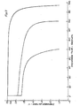
FIG. 7 depicts discharge curves comparing cells of this invention with conventional cells. -
FIGS. 8 and 9 are schematic depictions of a winding apparatus as it is winding cell components in a spiral form. -
FIG. 10 is a view of a mandrel which forms part of the winding apparatus. -
FIG. 11 is a depiction of the process used in placing the connector on a cell of the invention. - An electrochemical cell having both excellent charge and discharge characteristics is described. Technological breakthroughs in the fields of thin film handling have made it possible to create high rate electrochemical cells that have performance characteristics that are unprecedented in the field. Utilizing ultra-thin non perforated films of lead (for lead acid systems) in combination with extremely thin layers of active material, it is possible to create cells that have very high utilization of the active material, even at extreme discharge rates. Therefore, even under extreme loads there is virtually no voltage drop within the plates of the cell. An additional benefit provided when utilizing such ultra-thin plates, is that the increased amount of film cross-sectional area provides a large heat sink for heat generated during discharge. In many rapid rate discharge cells, heat build-up can be substantial. The present invention describes electrochemical cells with quite low current densities, thereby reducing heat creation.
- The present electrochemical cell is composed of ultra-thin non-perforated films of an electrochemically active metal --generally lead -- that is coated on each side with an electrochemically active paste. The positive and negative "plates" of the electrochemical cell are maintained apart from each other by separator material. The separator material also acts to absorb the electrolyte that is contained with the enclosed cell system.
- A diagrammatic view of a cell unit is seen in
FIG. 1 .Positive plate 10,separator 12 andnegative plate 14 constitute anelectrochemical unit cell 16. Both thepositive plate 10 and thenegative plate 12 consist of anultra-thin film 18 of lead partially coated on both major faces with a layer of a suitable electrochemicallyactive paste 20. It is important that the film not only be extremely thin, but that it not be perforated. One of the more critical elements of the present invention is that there not be anyactive material paste 20 at a distance of greater than 127 µm (0.005 inches) from thefilm 18 on which it is coated. Thefilms 18 utilized in the electrochemical cell are no greater than 127 µm (0.005 inches) thick. In the preferred embodiments, thefilms 18 are about 76 - 38 µm (0.003 to 0.0015 inches) thick. Handling such thin films and incorporating the same into functional electrochemical cells was previously thought to be impossible. In certain ways, the electrochemical cells of the present invention are constructed along the lines of standard electrolytic capacitors. Utilizing such thin films of active material, it is possible to greatly increase an important variable in such electrochemical cells, the ratio of surface area of film to the amount of active paste material. In the present invention, cells having greater than 26.0 square centimetres of surface area to gram of active material are described. - A thin layer of the
active material paste 20 is applied to a large portion of both major faces of the negative andpositive films 18. Each layer is, at the most, 127 µm (0.005 inches) thick, and in the preferred embodiments of the invention, the layers ofactive material paste 20 are about 50 - 75 µm (0.002 to 0.003 inches) thick. Both positive andnegative plates - In each
unit cell 16, thepositive plate 10, theseparator 12 and thenegative plate 14 are held against each other in a specific physical relation as seen inFIG. 1 . Both major faces of themetal films 18 are coated withactive material paste 20, except along alternatinghorizontal edges positive plate 10, the portions of the major faces 26 adjacent to the upperhorizontal edge 22 are not coated with theactive material paste 20, and onnegative plate 14, the portions of the major faces 28 adjacent to the lowerhorizontal edge 24 are not coated with theactive material paste 20. - The physical arrangement of
plate separator 12 is also shown inFIG. 1 . For example, thepositive plate 10 is positioned so that theuncoated portion 26 extends above both thenegative plate 12 and theseparator 12. To the top, theseparator 12 extends beyond thenegative plate 14 but not as far as thepositive plate 10 and to the bottom, theseparator 12 extends beyond thepositive plate 10 but not as far as thenegative plate 14. It could, of course, be constructed so that the relative position of the positive and negative plates be reversed. In an embodiment where a "D" size cell is produced, the negative andpositive film 18 is about 3.8 cm (1.5 inches) high. The uncoated ends extend about 6-8 mm beyond the coated plate, and theseparator 12 extends about 2-4 mm beyond the coated plate. The surfaces of thefilm 18 that are to be coated are preferably etched or roughened prior to application of theactive paste 20. This allows for a more adequate adhesion between the paste and the film. Preferably the electrochemical cell is constructed of a single spirally wound unit cell as is shown inFIG. 2 . Of course, the invention could also be employed utilizing parallel stacks of any number of unit cells. In thespirally wound configuration 30, a single continuous sheet ofseparator 12 may be employed to separate the negative 14 and positive 10 plates from each other as seen inFIG. 2 . - The preferred
terminal connector 32 is seen inFIG. 3 . Theterminal connector 32 is a component of the completed electrochemical cell formed near both the top (as seen inFIGs. 1 and5 , the positive terminal) and the bottom (as seen inFIGs. 1 and5 , the negative terminal) of the spirally wound plate and separator unit. The preferredterminal connector 32 is a conically shaped conductive element that is about the same diameter as the spirally wound cell, and that has a plurality of oblong shapedapertures 34 radiating outwardly from the centre portion of the circle. Theconnector 32 may have aconnector post 33 for ease in connection. An alternative connector 38 is seen inFIG. 4 This daisy-shaped connector has a plurality of radiatingwings 82 protruding out from thebody 84 of theconnector 80. - A unit cell having the physical relationships as shown in
FIGS. 1 and 2 and havingterminal connectors 32 in place, is seen inFIG. 5 . In the preferred embodiment, theconnectors 32 are applied to the top and bottom of the cell (where theuncoated portions uncoated portions negative plates separator 12, theuncoated portions separator 12, as seen inFIG. 4 . It can be seen, therefore, that the relative physical positions of the plates and separator is critical in obtaining a proper connection between theterminal connector 32 and theuncoated portions - The terminal arrangement described here provides an improved means for maximizing contact between the
respective plates terminal connector 32. The larger the surface area of each plate contacting theconnector 32, the less resistance created in the system, and the less heat generated. In a preferred embodiment, theconnectors 32 are permanently attached to the ends of the electrochemical cell by laser welding or plasma arc welding. Theoblong apertures 34 are spaced to allow access to the interior surface of theconnector 32 for welding. - An embodiment of the completed electrochemical
cell terminal assembly 40 is seen inFIG. 6 . The spirallywound unit cell 16 is held first in a polypropylene sealedcontainer 42 and second in astainless steel container 43 that is preferably equipped with vent means (not shown). Theterminal connectors 32 are held in place by atoroidal brace 42 that holdssuch connectors 32 in contact with theexterior terminal 44.Insulation washer 51 insulates the exterior terminal 44 from thestainless steel container 43. - When utilizing the lead acid system, the lead
non-perforated film 18 is preferably composed of lead that is at least 99.99% pure. In an alternative embodiment, the lead may be 99.50% pure and contain about 0.50% tin, As described above, thelead film 18 is 127 µm (0.005 inches) or less thick, and is preferably about .003 to .0015 inches thick. - For lead acid electrochemical cells, there are a number of widely known combinations of active material pastes 20 that are typically used. Any of these commonly used systems would be appropriate for use with this invention. For example, sulphated PbO pastes used on both the positive and negative plates provides a satisfactory system, as does the use of PbO and Pb304 on the positive plate and PbO on the negative plate. The use of sponge lead, litharge, red lead or lead oxide is also possible. The only important factor is that the
active material paste 20 be of a nature so that it can be applied to theultra-thin lead film 18 in a consistently thin layer, as described above. - As is commonly seen in the new generation of lead acid cells as exemplified in the McClelland and Nelson patents, the use of an
absorbent separator 12 is critical. As described above, there are several separator materials that have been disclosed for use specifically with lead acid system electrochemical cells. For the purposes of the present invention, any of the commonly used absorbent permeable separators will work suitably. In one preferred embodiment, the separator is a glass micro-fibre wherein 90% of the fibres are 1-4 microns in diameter, and 10% of the fibres are longer (up to 2.5 cm (1 inch )in length), being 95% porous in the uncompressed state. - When sulphated lead oxides are used as the
active material paste 20, the specific gravity of the sulphuric acid electrolyte solution used is between 1.20 and 1.32. Electrolyte concentration in the cell is established by adding an excess of electrolyte, and heating the cell in order to vent excess electrolyte. The type of vent used on the electrochemical cell may be similar to those described in the literature and known by those with ordinary skill in the art, and operates to vent excess gases when the internal pressure exceeds a certain level. The electrolyte remaining in the cell after heating and venting will be in an almost saturated state and some internal pressure (above atmospheric) will be maintained when in its normal operational state. In its operable state, the cell of the present invention is maintained so that the total void volume of the compressed separator and the active material is substantially filled, yet there is no free electrolyte present. The exact amount of electrolyte present in the cell, within these limits, is not critical to the functioning of the present invention. - As mentioned previously, electrochemical cells produced according to the present invention have distinctly superior discharge and recharge capabilities.
FIG. 7 shows the discharge curve for a lead acid electrochemical cell according to an embodiment of the present invention (C) in comparison with discharge curves for the cells described in United States Patent Nos.3,862,861 of McClelland et al. (A ) and4,769,299 of Nelson (B ). As can be seen, the improved performance is more than just an incremental increase. - The electrochemical cell used to create the discharge curve seen in
FIG 7 has the following characteristics: - The non-perforated lead film was composed of 99.50% lead and 0.50% tin;
- the lead films were 51 µm (0.002 inches) thick and were coated with a layer of 51µm (0.002 inches) thick of sulphated pastes -- the total plate thicknesses being 152 µm (0.006 inches);
- the electrolyte was sulphuric acid with a specific gravity of 1.28;
- the glass micro-fibre separator was 95% porous in its uncompressed state and contained 90% 1-4 micron diameter fibres and 10% larger fibres up to 2.5 cm (1 inch) in length and has a surface area of about 2 m2/g.
- In a "D" sized electrochemical cell, the lead films would be 112.5 cm (45 inches) long and 3.75 cm (1.5 inches) high, and there would be about 26.0 cm2 of surface area for each gram of active material paste.
-
FIG. 8 shows the basic elements required in one embodiment of the manufacture of electrochemical cells of the present invention. The central element of the process is therotatable mandrel 50. Themandrel 50 is characterized by acontinuous cavity 52 that is capable of receiving theseparator 12 during the winding process.Drag Rollers 54 are positioned in order to smoothly facilitate the movement of theseparator 12 towards themandrel 50. Thedrag rollers 54 also act to assure that the plates are wound tightly as the cell is being formed. The unique mandrel design allows the utilization of a single sheet ofseparator 12 to be used in each unit cell. Porousceramic rollers 56 through which the separator must pass are also shown. In a preferred embodiment of the invention, theceramic rollers 56 are associated with areservoir 57 containing electrolyte. Metering means 58 are associated with thereservoir 57, that allow controlled amounts of electrolyte into the interior area of theceramic rollers 56. Theceramic rollers 56 are constructed such that electrolyte contained within its interior surfaces will flow to the surface of the rollers, where the electrolyte will be absorbed into theporous separator 12 that passes between the rollers. By this procedure it is possible to assure that a precise amount of electrolyte will be incorporated into the wound electrochemical cell. The amount of electrolyte added to the separator is small enough so that little if any electrolyte will be "squeezed" from theseparator 12 during the winding process as the separator andplates - Of course, the electrolyte could be added to the cell via conventional techniques. For example, after winding the cell and placement into a canister, liquid electrolyte may be added to the cell at this time.
- The
negative plate 14 is shown inFIG. 9 as it is advanced toward themandrel 50. Thepositive plate 10 is seen advancing toward themandrel 50 from the opposite direction, and both being perpendicular to the general plane of theseparator 12. Theplates mandrel 50 and held on aplate carriage 60. Theplate carriages 60 act as conveyor belts to facilitate the advancement of the plates towards the mandrel. Theactive material paste 20 is applied to both major faces of theplates paste 20 may be accomplished by the use of a high pressure brush, or a high pressure spray nozzle. After theactive material paste 20 has been applied to theplates paste 20 as applied contains a relatively small amount of moisture, and will dry adequately in a very short period of time. - In a preferred embodiment of the invention, some mechanism (not shown) is provided before the paste application zone in which the surfaces of the plates which are to be coated are scored or etched. Such scoring aids in the adhering of the active material paste to the plates, and can be accomplished via chemical or physical processes.
- The
plate carriages 60 are designed so that the front edge (the edge closest the mandrel 50) can be moved horizontally towards or away from themandrel 50. It should be remembered that the plates of the present invention are extremely thin, even when coated, and will have little or no rigidity. - The production of the electrochemical cell proceeds through a series of steps. The process begins by placement of the separator around the
drag rollers 54, through the opening in themandrel 50 and between the two sets of porousceramic rollers 56. The separator sheet must be long enough, both above and below themandrel 50, to supply sufficient separator for the entire electrochemical cell - In a preferred embodiment, a single source of separator may be utilized either above or below the
mandrel 50, and the initial step of the process would be the threading of the separator through theceramic rollers 56, past thefirst drag roller 54, through the opening in the mandrel and past thesecond drag roller 54. At this stage, the entire amount of separator to be used in the cell has been infiltrated with electrolyte. - In an alternative embodiment, pre-cut sections of separator may be utilized. In such an embodiment, the separator may be placed in the proper position by laterally moving the separator between the various elements and having the correct amount of separator, both above and below the mandrel, for one cell unit. In this embodiment, the separator would have to be run through the electrolyte containing ceramic rollers prior to being put in place relative to the mandrel.
- Once the separator is in place, the mandrel is rotated about its axis one half turn (as seen by arrow A) so that the opening in the mandrel is now in a horizontal position. At this point, the
plate carriages 60 advance toward themandrel 50 so that theplates mandrel 50 and the drag rollers as seen inFIG. 9 . The drag rollers are then allowed to advance forward in order to engage the plates. -
FIG. 10 shows a detailed view of themandrel 50 of the present invention. In association with the separator-receiving gap, is a clamp likedevice 80. Theclamp 80 operates to facilitate the securing of the separator into themandrel 50 after it has been put in place. Once cell formation is completed, theclamp 80 releases, and the cell may be more easily removed from the mandrel. - Once the plates are engaged, the plate carriages are moved horizontally away from the
mandrel 50. The mandrel can now be rotated (counter clockwise in the example shown inFIG. 9 ), in order to create a cell unit. Thedrag rollers 54 create a certain amount of pressure against the expanding diameter of the cell unit as it is being formed. The "tightness" of the winding will be controlled by a number of factors including: the speed of revolution of themandrel 50; the tension exerted by the drag rollers against the growing cell, and the source tension of the separator and plates relative to themandrel 50. As the desired diameter of the cell unit is about to be attained, theplates plate carriages 60 nearest themandrel 50. Tail wrap is attached to the ends of the plates and, once wrapped around the cell, may be heat sealed with a sizing roll or hot drag wires. Once sealed in the spirally wound configuration, the mandrel and drag rollers may be retracted and the cell may be incorporated into a useful means. The processing of the wound and sealed cell may be accomplished by procedures commonly known and available to those skilled in the art. - As described above, and as seen in
FIG. 11 , the construction and manufacture of the connectors of the present invention is also unique. The cell is provided with positive and negative ends that consist of the top and bottom portions of the spirally wound plates. The connector is put in place on the top and bottom of the cell by the application of a circular movement, forcing the flexible plate elements to press tightly against each other to form an essentially continuous plate or cover above and below the spirally wound cell. Once put in place on the cell via the circular motion, the connector is secured via arc welding or laser welding techniques. This construction provides a low resistance pathway for electricity during recharge or discharge. - As should be clear from the above description, both the plates and the separator are being treated as they are being wound into the mandrel. The plate is being coated with the active material, which is then flash dried -- all before reaching the mandrel and the growing cell. The separator is being impregnated with electrolyte as it passes between the porous ceramic rollers.
- The present invention has applications in lead-acid cells, and in particular, the lead acid and nickel chromium systems. The descriptions given and the example presented are for the purposes of illustration and are not meant to limit the claims of the application as set forth below.
Claims (26)
- A lead-acid rechargeable electrochemical cell, comprising:interleaved first and second plates of opposite polarity, the first plate comprising a non-perforate film made from metal and a porous electrochemically active paste coated onto both sides of the film, the first plate being less than 380 µm (0.015 inches) thick and the first plate film having a thickness not greater than 127 µm (0.005 inches);a permeable porous compressible separator interposed between the first and second plates, the separator having acid electrolyte in the pores; anda container to contain the plates and separator.
- The cell of claim 1, wherein said first plate has a thickness not greater than 254 µm (0.01 inches).
- The cell of claim 2, wherein said first plate has a thickness less than 203 µm (0.008 inches)
- The cell of claim 3, wherein said first plate has a thickness of 127-203 µm (0.005-0.008 inches).
- The cell of any preceding claim, wherein the first plate film is of thickness less than 76 µm (0.003 inches)
- The cell of claim 5, wherein the first plate film is of thickness 76-127µm (0.003-0.005 inches).
- The cell of claim 6, wherein the layers of electrochemically active paste are of thickness 50-76µm (0.002-0.003 inches).
- The cell of any preceding claim, wherein the first plate film comprises at least 99% lead.
- The cell of claim 8, wherein the first plate film comprises 99.99% lead.
- The cell of claim 8, wherein the first plate film comprises 99.50% lead and 0.50% tin.
- The cell of any preceding claim, wherein the second plate comprises a film made from metal with a porous electrochemically active paste coated onto both sides of the film.
- The cell of claim 11, wherein the second plate has a thickness not greater than 380µm (0.015 inches).
- The cell of claim 12 wherein the second plate has a thickness not greater than 250µm (0.01 inches).
- The cell of claim 13, wherein the second plate has a thickness of 127-203µm (0.005-0.008 inches).
- The cell of any of claims 11-14, wherein the second plate film has a thickness of not greater than 127µm (0.005 inches).
- The cell of claim 15, wherein the second plate film is of thickness 76-127µm (0.003-0.005 inches).
- The method of any preceding claim, wherein the second plate film comprises at least 99% lead.
- The cell of claim 17, wherein the second plate comprises at least 99.99% lead.
- The cell of claim 17, wherein the second plate film comprises 99.5% lead and 0.5% tin.
- The cell of any of claims 1 to 16 wherein the second plate film is not primarily made of lead.
- The cell of any preceding claims, wherein said first and second plates are each formed of a non-perforate film of electrochemically active metal partially coated with a layer of electrochemically active paste, the geometric surface are of said film being at least about 26.0 square centimetres per gram of said paste.
- The cell of any preceding claim, wherein said first plate, second plate and separator are spirally wound.
- The cell of claim 22, wherein the spiral winding is substantially circular in cross section.
- The cell of any preceding claim comprising:first and second plates each formed of a non-perforate film of metal partially coated with a layer of electrochemically active paste,a porous, compressible separator interposed between said positive and negative plates and compressed against the major faces of such plates to define, in combination, a cell unit having first and second horizontal edges; said cell unit being spirally wound about a central axis and held tightly in a tubular configuration,wherein on the first horizontal edge of said cell unit, said first plate extends beyond the edge of said separator, and said film is not coated with said paste in the portion extending beyond said separator andwherein on the second horizontal edge of said separator, and said second film is not coated with said paste in the portion extending beyond said separator; andfirst and second terminal connectors are connected to the first and second horizontal edges of the spirally wound electrochemical cell, each connector being in contact with one continuous edge of its plate where said uncoated portion of said plate extends beyond the edge of the separator.
- The cell of any of claims 22-24, where the separator has a metered amount of electrolyte in its pores, said amount being sufficiently small that little, if any, becomes squeezed from the separator on spirally winding.
- The cell of any preceding claim, having an inter-plate spacing of about 127 - 178 µm (0.005 to 0.007 inches).
Applications Claiming Priority (5)
| Application Number | Priority Date | Filing Date | Title |
|---|---|---|---|
| US413272 | 1982-08-30 | ||
| US07/366,867 US5047300A (en) | 1989-06-14 | 1989-06-14 | Ultra-thin plate electrochemical cell |
| US366867 | 1989-06-14 | ||
| US07/413,272 US5045086A (en) | 1989-06-14 | 1989-09-27 | Method for manufacture of electrochemical cell |
| EP90911144A EP0494147B1 (en) | 1989-06-14 | 1990-06-14 | Ultra-thin plate electrochemical cell |
Related Parent Applications (2)
| Application Number | Title | Priority Date | Filing Date |
|---|---|---|---|
| EP90911144A Division EP0494147B1 (en) | 1989-06-14 | 1990-06-14 | Ultra-thin plate electrochemical cell |
| EP90911144.5 Division | 1991-01-02 |
Publications (3)
| Publication Number | Publication Date |
|---|---|
| EP0961336A2 EP0961336A2 (en) | 1999-12-01 |
| EP0961336A3 EP0961336A3 (en) | 2003-10-29 |
| EP0961336B1 true EP0961336B1 (en) | 2009-02-11 |
Family
ID=27003549
Family Applications (2)
| Application Number | Title | Priority Date | Filing Date |
|---|---|---|---|
| EP99116071A Expired - Lifetime EP0961336B1 (en) | 1989-06-14 | 1990-06-14 | Ultra-thin plate electromechanical cell |
| EP99116070A Expired - Lifetime EP0961335B1 (en) | 1989-06-14 | 1990-06-14 | Method of manufacture of an ultra-thin plate electrochemical cell |
Family Applications After (1)
| Application Number | Title | Priority Date | Filing Date |
|---|---|---|---|
| EP99116070A Expired - Lifetime EP0961335B1 (en) | 1989-06-14 | 1990-06-14 | Method of manufacture of an ultra-thin plate electrochemical cell |
Country Status (5)
| Country | Link |
|---|---|
| US (1) | US5045086A (en) |
| EP (2) | EP0961336B1 (en) |
| AT (3) | ATE190758T1 (en) |
| DE (3) | DE69034262D1 (en) |
| ES (1) | ES2146198T3 (en) |
Families Citing this family (35)
| Publication number | Priority date | Publication date | Assignee | Title |
|---|---|---|---|---|
| US5198313A (en) * | 1989-06-14 | 1993-03-30 | Bolder Battery, Inc. | Battery end connector |
| EP0556326A4 (en) * | 1990-11-09 | 1995-03-29 | Weiler Eng Inc | Method and apparatus for winding a core for an electrochemical cell and processing thereof |
| DE4241037C1 (en) * | 1992-12-05 | 1994-04-28 | Deutsche Automobilgesellsch | Electrical accumulator - comprises outer housing containing set of electrode plates surrounded by insulating container with narrow sides having gas=escape channels formed between raised areas |
| US5370711A (en) * | 1993-07-21 | 1994-12-06 | Ev Energy Systems, Inc. | Method for making an electrical energy storage device |
| US5958621A (en) * | 1995-05-19 | 1999-09-28 | Johnson Controls Technology Company | Two-step pasting of thin electrodes |
| US6004689A (en) * | 1995-09-27 | 1999-12-21 | Bolder Technologies Corporation | Battery case |
| US5700299A (en) * | 1996-12-12 | 1997-12-23 | Eveready Battery Company, Inc. | Battery core winder and method of winding a battery core |
| US6063525A (en) * | 1997-11-20 | 2000-05-16 | Bipolar Technologies Corp. | Source of electrical power for an electric vehicle and other purposes, and related methods |
| US6051336A (en) * | 1998-01-19 | 2000-04-18 | Johnson Controls Technology | Battery case for thin metal film cells |
| CN1291357A (en) | 1998-01-19 | 2001-04-11 | 约翰逊控制技术公司 | Vent cover for battery |
| US6221524B1 (en) | 1998-01-19 | 2001-04-24 | Johnson Controls Technology Company | Strap for thin metal film battery |
| EP1033768B1 (en) | 1999-03-04 | 2002-09-18 | Wilson Greatbatch Ltd. | Wound cell stack design for enhanced battery performance |
| KR100305350B1 (en) * | 1999-07-01 | 2001-11-01 | 이계안 | assembling machine for negative electrode plate of Ni-MH battery and assembling process therefor |
| US6292381B1 (en) * | 1999-12-16 | 2001-09-18 | S-B Power Tool Company | AC to DC power supply with supplemental energy storage |
| DE10015823A1 (en) * | 2000-03-30 | 2001-10-18 | Epcos Ag | Enclosed layered stack, eg for batteries, consists of intermediate layers which are sepd from each other, with a wound strip between them. |
| US6534212B1 (en) | 2000-05-05 | 2003-03-18 | Hawker Energy Products, Inc. | High performance battery and current collector therefor |
| US6316148B1 (en) | 2000-08-31 | 2001-11-13 | Condord Battery Corporation | Foil-encapsulated, lightweight, high energy electrodes for lead-acid batteries |
| US6586136B1 (en) | 2000-11-16 | 2003-07-01 | Concorde Battery Corporation | Lightweight, low resistance electrode plate for lead-acid batteries |
| US6566010B1 (en) | 2000-11-16 | 2003-05-20 | Concorde Battery Corporation | High energy, lightweight, lead-acid storage battery |
| JP2002298924A (en) * | 2001-03-30 | 2002-10-11 | Toray Eng Co Ltd | Secondary battery, and method and device for manufacturing secondary battery |
| US8094771B2 (en) * | 2003-11-21 | 2012-01-10 | Global Technologies, Inc. | Nuclear voltaic cell |
| US7011805B2 (en) * | 2004-03-19 | 2006-03-14 | Ges Technologies Ip Gmbh | Production of tetrabasic lead sulfate from solid state reactions for the preparation of active plates to be used in lead-acid batteries |
| US20060039852A1 (en) * | 2004-08-19 | 2006-02-23 | Johnson Controls Technology Company | Method for making lead oxide for lead-acid batteries |
| US20080113268A1 (en) * | 2006-10-23 | 2008-05-15 | Buiel Edward R | Recombinant Hybrid Energy Storage Device |
| KR101023865B1 (en) | 2009-02-25 | 2011-03-22 | 에스비리모티브 주식회사 | Rechargeable battery |
| US9054387B2 (en) | 2010-04-07 | 2015-06-09 | Medtronic, Inc. | Electrode assembly including mandrel having removable portion |
| US8685557B2 (en) | 2010-04-07 | 2014-04-01 | Medtronic, Inc. | Electrode assembly including mandrel having a removable portion |
| US9299971B2 (en) | 2010-10-06 | 2016-03-29 | Medtronic, Inc. | Common carrier for the integrated mandrel battery assembly |
| US8832914B2 (en) | 2010-10-06 | 2014-09-16 | Medtronic, Inc | Coiling device for making an electrode assembly and methods of use |
| US9559339B2 (en) * | 2011-04-19 | 2017-01-31 | Samsung Sdi Co., Ltd. | Secondary battery |
| CN103891024B (en) * | 2011-10-31 | 2017-04-12 | 三洋电机株式会社 | Cell provided with spiral electrode, and method for manufacturing same |
| US9005802B2 (en) | 2011-12-21 | 2015-04-14 | Medtronic, Inc. | Electrode assembly with hybrid weld |
| US9083053B2 (en) | 2011-12-21 | 2015-07-14 | Medtronic, Inc. | Through weld interconnect joint |
| KR102499324B1 (en) * | 2015-10-30 | 2023-02-13 | 삼성에스디아이 주식회사 | Rolling Device for Secondary Battery |
| KR20200082565A (en) * | 2018-12-31 | 2020-07-08 | 현대자동차주식회사 | Negative electrode comprising active material having a core-shell structure for secondary battery, menufacturing method of thereof, and secondary battery comprising the same |
Family Cites Families (22)
| Publication number | Priority date | Publication date | Assignee | Title |
|---|---|---|---|---|
| US2883443A (en) * | 1956-07-13 | 1959-04-21 | Ruetschi Karl | Lead-acid storage battery |
| DE1248770B (en) * | 1964-05-16 | 1967-08-31 | VARTA AKTIENGESELL SCHAFT, Frankfurt/M | Mi + high current resilient electrical accumulator with wound electrodes |
| FR1510827A (en) * | 1966-04-01 | 1968-01-26 | Accumulateurs Fixes | Improvements to electrolytic cells, accumulators and electric batteries |
| US3395043A (en) * | 1967-05-09 | 1968-07-30 | Shoeld Mark | Storage battery having spiral electrodes of the pasted type |
| US3494800A (en) * | 1968-04-08 | 1970-02-10 | Mark Shoeld | Method of making lead acid storage battery |
| DE2403222A1 (en) * | 1974-01-24 | 1975-08-07 | Walter Nimmerrichter | Plates for light-weight accumulators - wound from plus and minus metal foils with two separator strips |
| CH590566A5 (en) * | 1974-03-27 | 1977-08-15 | Spiracell Sa | |
| US4064725A (en) * | 1976-10-18 | 1977-12-27 | The Gates Rubber Company | Apparatus for making spirally wound electrochemical cells |
| SU674124A1 (en) * | 1977-01-06 | 1979-07-15 | Предприятие П/Я В-2410 | Method of cooling into a roll a stack of electrodes with separators for chemical current source |
| US4099401A (en) * | 1977-06-27 | 1978-07-11 | The Gates Rubber Company | Method of producing spirally wound electrochemical cells |
| US4158300A (en) * | 1977-12-16 | 1979-06-19 | The Gates Rubber Company | Apparatus for producing a spirally wound electrochemical cell |
| US4212179A (en) * | 1978-10-12 | 1980-07-15 | The Gates Rubber Company | Driven mandrel and method |
| US4295029A (en) * | 1979-05-29 | 1981-10-13 | The Gates Rubber Company | Battery strap connection welding method |
| SE8005528L (en) * | 1980-08-01 | 1982-02-05 | Erik G Sundberg | ELECTRICAL BLYACK CUMULATOR WITH THIN ELECTRODES |
| JPS58119154A (en) * | 1982-01-09 | 1983-07-15 | Yuasa Battery Co Ltd | Alkaline storage battery |
| JPS59103282A (en) * | 1982-12-03 | 1984-06-14 | Japan Storage Battery Co Ltd | Manufacture of spiral electrode body |
| US4495259A (en) * | 1983-02-11 | 1985-01-22 | The Gates Rubber Company | Vibration resistant battery |
| JPS59219868A (en) * | 1983-05-30 | 1984-12-11 | Shin Kobe Electric Mach Co Ltd | Manufacture of nickel cadmium storage battery |
| US4606982A (en) * | 1985-05-09 | 1986-08-19 | Gates Energy Products, Inc. | Sealed lead-acid cell and method |
| JPS62147661A (en) * | 1985-12-23 | 1987-07-01 | Sanyo Electric Co Ltd | Manufacture of spiral electrode |
| US4780379A (en) * | 1987-10-06 | 1988-10-25 | Gates Energy Products, Inc. | Multicell recombinant lead-acid battery with vibration resistant intercell connector |
| US4963446A (en) * | 1989-04-05 | 1990-10-16 | Eveready Battery Co., Inc. | Inwardly indented edge electrode assembly |
-
1989
- 1989-09-27 US US07/413,272 patent/US5045086A/en not_active Expired - Lifetime
-
1990
- 1990-06-14 DE DE69034262T patent/DE69034262D1/en not_active Expired - Lifetime
- 1990-06-14 DE DE69033485T patent/DE69033485T2/en not_active Expired - Fee Related
- 1990-06-14 AT AT90911144T patent/ATE190758T1/en not_active IP Right Cessation
- 1990-06-14 AT AT99116070T patent/ATE393968T1/en not_active IP Right Cessation
- 1990-06-14 EP EP99116071A patent/EP0961336B1/en not_active Expired - Lifetime
- 1990-06-14 DE DE69034252T patent/DE69034252D1/en not_active Expired - Lifetime
- 1990-06-14 AT AT99116071T patent/ATE422717T1/en not_active IP Right Cessation
- 1990-06-14 ES ES90911144T patent/ES2146198T3/en not_active Expired - Lifetime
- 1990-06-14 EP EP99116070A patent/EP0961335B1/en not_active Expired - Lifetime
Also Published As
| Publication number | Publication date |
|---|---|
| DE69033485T2 (en) | 2000-06-29 |
| ATE190758T1 (en) | 2000-04-15 |
| EP0961335A3 (en) | 2003-10-29 |
| DE69034252D1 (en) | 2008-06-12 |
| US5045086A (en) | 1991-09-03 |
| DE69034262D1 (en) | 2009-03-26 |
| ATE393968T1 (en) | 2008-05-15 |
| DE69033485D1 (en) | 2000-04-20 |
| EP0961336A2 (en) | 1999-12-01 |
| EP0961335B1 (en) | 2008-04-30 |
| EP0961336A3 (en) | 2003-10-29 |
| ATE422717T1 (en) | 2009-02-15 |
| EP0961335A2 (en) | 1999-12-01 |
| ES2146198T3 (en) | 2000-08-01 |
Similar Documents
| Publication | Publication Date | Title |
|---|---|---|
| EP0961336B1 (en) | Ultra-thin plate electromechanical cell | |
| US5047300A (en) | Ultra-thin plate electrochemical cell | |
| EP0494147B1 (en) | Ultra-thin plate electrochemical cell | |
| US5368961A (en) | Thin plate electrochemical cell | |
| US6949313B2 (en) | Battery with a microcorrugated, microthin sheet of highly porous corroded metal | |
| US3486940A (en) | Storage battery having a positive electrode comprising a supporting base of titanium nitride having a surface film of non-polarizing material | |
| US6069107A (en) | Recharge catalyst with thin film carbon coating, metal-air electrode including said catalyst and methods for making said catalyst and electrode | |
| US20170155171A1 (en) | Lead-acid accumulator and method for manufacturing such an accumulator | |
| KR20150012242A (en) | Aqueous-based electric double-layer capacitor | |
| US6127060A (en) | Recharge catalyst with thin film low corrosion coating, metal-air electrode including said catalyst and methods for making said catalyst and electrode | |
| US5993494A (en) | Method of manufacturing modular components for a bipolar battery and the resulting bipolar battery | |
| US4855196A (en) | Multilaminate material and separator assembly for electrochemical cells | |
| EP0301647B1 (en) | Electrochemical cell | |
| US3697328A (en) | Duplex electrode construction using continuous metal carrier strip coated on one side with conductive adhesive | |
| JPH04206468A (en) | Sealed alkali-zinc storage battery | |
| US20240105914A1 (en) | Bipolar battery plate and fabrication thereof | |
| WO1994029909A1 (en) | Method and apparatus for assembling electrochemical cell | |
| JP2768176B2 (en) | Lead storage battery and method of manufacturing the same | |
| CA1102409A (en) | Battery plates covered with porous thermoplastic resin | |
| JPS6266557A (en) | Jar of lead-storage battery | |
| US20140272527A1 (en) | Separator components and system for energy storage and conversion devices | |
| JPS5840779A (en) | Lead storage battery | |
| JPS5933754A (en) | Lead-acid battery | |
| WO1984002806A1 (en) | Sandwich electrode for a lead acid battery, a method for manufacturing such an electrode and a battery comprising the same | |
| JPH0810589B2 (en) | Lead acid battery |
Legal Events
| Date | Code | Title | Description |
|---|---|---|---|
| PUAI | Public reference made under article 153(3) epc to a published international application that has entered the european phase |
Free format text: ORIGINAL CODE: 0009012 |
|
| 17P | Request for examination filed |
Effective date: 19990816 |
|
| AC | Divisional application: reference to earlier application |
Ref document number: 494147 Country of ref document: EP |
|
| AK | Designated contracting states |
Kind code of ref document: A2 Designated state(s): AT BE CH DE DK ES FR GB GR IT LI LU NL SE |
|
| RAP1 | Party data changed (applicant data changed or rights of an application transferred) |
Owner name: GP BATTERIES INTERNATIONAL LIMITED |
|
| PUAL | Search report despatched |
Free format text: ORIGINAL CODE: 0009013 |
|
| AK | Designated contracting states |
Kind code of ref document: A3 Designated state(s): AT BE CH DE DK ES FR GB IT LI LU NL SE |
|
| RIC1 | Information provided on ipc code assigned before grant |
Ipc: 7H 01M 2/26 B Ipc: 7H 01M 2/30 B Ipc: 7H 01M 10/12 B Ipc: 7H 01M 10/04 A |
|
| AKX | Designation fees paid |
Designated state(s): AT BE CH DE DK ES FR GB IT LI LU NL SE |
|
| 17Q | First examination report despatched |
Effective date: 20040622 |
|
| GRAP | Despatch of communication of intention to grant a patent |
Free format text: ORIGINAL CODE: EPIDOSNIGR1 |
|
| RTI1 | Title (correction) |
Free format text: ULTRA-THIN PLATE ELECTROMECHANICAL CELL |
|
| GRAS | Grant fee paid |
Free format text: ORIGINAL CODE: EPIDOSNIGR3 |
|
| GRAA | (expected) grant |
Free format text: ORIGINAL CODE: 0009210 |
|
| AC | Divisional application: reference to earlier application |
Ref document number: 0494147 Country of ref document: EP Kind code of ref document: P |
|
| AK | Designated contracting states |
Kind code of ref document: B1 Designated state(s): AT BE CH DE DK ES FR GB IT LI LU NL SE |
|
| REG | Reference to a national code |
Ref country code: GB Ref legal event code: FG4D |
|
| REG | Reference to a national code |
Ref country code: CH Ref legal event code: EP |
|
| REF | Corresponds to: |
Ref document number: 69034262 Country of ref document: DE Date of ref document: 20090326 Kind code of ref document: P |
|
| REG | Reference to a national code |
Ref country code: SE Ref legal event code: TRGR |
|
| PG25 | Lapsed in a contracting state [announced via postgrant information from national office to epo] |
Ref country code: NL Free format text: LAPSE BECAUSE OF FAILURE TO SUBMIT A TRANSLATION OF THE DESCRIPTION OR TO PAY THE FEE WITHIN THE PRESCRIBED TIME-LIMIT Effective date: 20090211 Ref country code: ES Free format text: LAPSE BECAUSE OF FAILURE TO SUBMIT A TRANSLATION OF THE DESCRIPTION OR TO PAY THE FEE WITHIN THE PRESCRIBED TIME-LIMIT Effective date: 20090522 |
|
| NLV1 | Nl: lapsed or annulled due to failure to fulfill the requirements of art. 29p and 29m of the patents act | ||
| PG25 | Lapsed in a contracting state [announced via postgrant information from national office to epo] |
Ref country code: AT Free format text: LAPSE BECAUSE OF FAILURE TO SUBMIT A TRANSLATION OF THE DESCRIPTION OR TO PAY THE FEE WITHIN THE PRESCRIBED TIME-LIMIT Effective date: 20090211 |
|
| PGFP | Annual fee paid to national office [announced via postgrant information from national office to epo] |
Ref country code: IT Payment date: 20090615 Year of fee payment: 20 |
|
| PG25 | Lapsed in a contracting state [announced via postgrant information from national office to epo] |
Ref country code: BE Free format text: LAPSE BECAUSE OF FAILURE TO SUBMIT A TRANSLATION OF THE DESCRIPTION OR TO PAY THE FEE WITHIN THE PRESCRIBED TIME-LIMIT Effective date: 20090211 |
|
| PG25 | Lapsed in a contracting state [announced via postgrant information from national office to epo] |
Ref country code: DK Free format text: LAPSE BECAUSE OF FAILURE TO SUBMIT A TRANSLATION OF THE DESCRIPTION OR TO PAY THE FEE WITHIN THE PRESCRIBED TIME-LIMIT Effective date: 20090211 |
|
| PGFP | Annual fee paid to national office [announced via postgrant information from national office to epo] |
Ref country code: GB Payment date: 20090529 Year of fee payment: 20 Ref country code: DE Payment date: 20090622 Year of fee payment: 20 |
|
| PLBE | No opposition filed within time limit |
Free format text: ORIGINAL CODE: 0009261 |
|
| STAA | Information on the status of an ep patent application or granted ep patent |
Free format text: STATUS: NO OPPOSITION FILED WITHIN TIME LIMIT |
|
| 26N | No opposition filed |
Effective date: 20091112 |
|
| REG | Reference to a national code |
Ref country code: CH Ref legal event code: PL |
|
| REG | Reference to a national code |
Ref country code: FR Ref legal event code: ST Effective date: 20100226 |
|
| PG25 | Lapsed in a contracting state [announced via postgrant information from national office to epo] |
Ref country code: LI Free format text: LAPSE BECAUSE OF NON-PAYMENT OF DUE FEES Effective date: 20090630 Ref country code: FR Free format text: LAPSE BECAUSE OF NON-PAYMENT OF DUE FEES Effective date: 20090630 Ref country code: CH Free format text: LAPSE BECAUSE OF NON-PAYMENT OF DUE FEES Effective date: 20090630 |
|
| REG | Reference to a national code |
Ref country code: GB Ref legal event code: PE20 Expiry date: 20100613 |
|
| PG25 | Lapsed in a contracting state [announced via postgrant information from national office to epo] |
Ref country code: GB Free format text: LAPSE BECAUSE OF EXPIRATION OF PROTECTION Effective date: 20100613 |
|
| PG25 | Lapsed in a contracting state [announced via postgrant information from national office to epo] |
Ref country code: LU Free format text: LAPSE BECAUSE OF NON-PAYMENT OF DUE FEES Effective date: 20090614 |
|
| PG25 | Lapsed in a contracting state [announced via postgrant information from national office to epo] |
Ref country code: SE Free format text: LAPSE BECAUSE OF NON-PAYMENT OF DUE FEES Effective date: 20090615 |
|
| PG25 | Lapsed in a contracting state [announced via postgrant information from national office to epo] |
Ref country code: DE Free format text: LAPSE BECAUSE OF EXPIRATION OF PROTECTION Effective date: 20100614 |