EP0961331A1 - Arrangement for implementing a safety feature in a battery, and a battery - Google Patents
Arrangement for implementing a safety feature in a battery, and a battery Download PDFInfo
- Publication number
- EP0961331A1 EP0961331A1 EP99660067A EP99660067A EP0961331A1 EP 0961331 A1 EP0961331 A1 EP 0961331A1 EP 99660067 A EP99660067 A EP 99660067A EP 99660067 A EP99660067 A EP 99660067A EP 0961331 A1 EP0961331 A1 EP 0961331A1
- Authority
- EP
- European Patent Office
- Prior art keywords
- battery
- conductive strip
- battery shell
- arrangement
- slit
- Prior art date
- Legal status (The legal status is an assumption and is not a legal conclusion. Google has not performed a legal analysis and makes no representation as to the accuracy of the status listed.)
- Withdrawn
Links
Images


Classifications
-
- H—ELECTRICITY
- H01—ELECTRIC ELEMENTS
- H01M—PROCESSES OR MEANS, e.g. BATTERIES, FOR THE DIRECT CONVERSION OF CHEMICAL ENERGY INTO ELECTRICAL ENERGY
- H01M50/00—Constructional details or processes of manufacture of the non-active parts of electrochemical cells other than fuel cells, e.g. hybrid cells
- H01M50/50—Current conducting connections for cells or batteries
- H01M50/572—Means for preventing undesired use or discharge
- H01M50/574—Devices or arrangements for the interruption of current
- H01M50/578—Devices or arrangements for the interruption of current in response to pressure
-
- H—ELECTRICITY
- H01—ELECTRIC ELEMENTS
- H01M—PROCESSES OR MEANS, e.g. BATTERIES, FOR THE DIRECT CONVERSION OF CHEMICAL ENERGY INTO ELECTRICAL ENERGY
- H01M50/00—Constructional details or processes of manufacture of the non-active parts of electrochemical cells other than fuel cells, e.g. hybrid cells
- H01M50/50—Current conducting connections for cells or batteries
- H01M50/572—Means for preventing undesired use or discharge
- H01M50/574—Devices or arrangements for the interruption of current
-
- H—ELECTRICITY
- H01—ELECTRIC ELEMENTS
- H01M—PROCESSES OR MEANS, e.g. BATTERIES, FOR THE DIRECT CONVERSION OF CHEMICAL ENERGY INTO ELECTRICAL ENERGY
- H01M50/00—Constructional details or processes of manufacture of the non-active parts of electrochemical cells other than fuel cells, e.g. hybrid cells
- H01M50/50—Current conducting connections for cells or batteries
-
- H—ELECTRICITY
- H01—ELECTRIC ELEMENTS
- H01M—PROCESSES OR MEANS, e.g. BATTERIES, FOR THE DIRECT CONVERSION OF CHEMICAL ENERGY INTO ELECTRICAL ENERGY
- H01M6/00—Primary cells; Manufacture thereof
- H01M6/04—Cells with aqueous electrolyte
- H01M6/06—Dry cells, i.e. cells wherein the electrolyte is rendered non-fluid
- H01M6/12—Dry cells, i.e. cells wherein the electrolyte is rendered non-fluid with flat electrodes
Definitions
- the invention relates to an arrangement defined in the preamble of claim 1 for preventing damage caused by a battery, and a battery defined in the preamble of claim 10.
- Misuse, such as overcharging, of a battery may result in generation of gas inside the battery and, hence, an increase in the internal pressure of the battery.
- the pressure may cause corrosive substances to spread outside the battery, resulting in damage to nearby circuits and equipment.
- misuse of the battery may result in a relatively dramatic build-up of thermal energy in the battery if electrical energy is no longer chemically absorbed. Accumulation of heat may also cause damage to structures around the battery.
- Misuse of a battery is usually prevented by means of a safety circuit in the charging device:
- the battery voltage is monitored, and when it has reached a predetermined level corresponding to full charge, the charging current is electronically switched off.
- the charging current is not switched back on until the battery voltage has dropped to a second level considerably lower than the first one.
- Such an external safety circuit by itself provides inadequate protection.
- the charging device may become faulty so that the protection will not work.
- the battery may be connected to a charging device of an incorrect type, or even the wrong way around by its terminals. Safe batteries therefore have got internal protection in case of misuse.
- An object of the invention is to reduce said disadvantages related to the prior art.
- the protection method according to the invention is characterized by what is expressed in the independent claims 1 and 10. Preferred embodiments of the invention are presented in the dependent claims.
- a battery is manufactured such that pressure generated inside it will cause at least one of the battery's conductors to tear in two, thus interrupting the flow of current through said conductor.
- the battery shell is made at least partly of a flexible material and is hermetically sealed.
- Said conductors are thin strips and their strength, or at least the strength of one of them, is reduced at one point e.g. by cutting a slit on a side of the conductor.
- the conductive strip is attached at one side of said point to the upper portion of the battery shell and at the other side to the lower portion of the battery shell.
- An advantage of the invention is that an increase in the internal pressure of a battery will not result in the spreading of corrosive chemicals outside the apparatus. Another advantage of the invention is that the charging of a battery is stopped before the battery will heat up its surroundings possibly to a damaging extent. A further advantage of the invention is that protection according to the invention will not cause extra energy consumption during normal operation of the battery. A yet further advantage of the invention is that it finds particular utility in batteries having a flexible construction; say, lithium polymer batteries, which are becoming more popular and for which there is no effective protection at the moment. Yet another advantage of the invention is that the costs of the arrangement according to the invention are relatively small. The costs are brought down among other things by the fact that the invention will make protective components redundant.
- Fig. 2 shows an example of the conductive strip according to the invention.
- a strip 20 having a width w at both ends has been cut from a thin metal sheet.
- the shape of the strip has a transition corresponding roughly to the width w as shown in Fig. 2a.
- Transition means that for the length d of the transition area 21 the width of the strip is about 2w and that after the transition area 21 the strip continues with the same width and direction as before the transition area but moved to the side for the width w.
- the strip portion corresponding to the transition area 21 is divided into a first part 23, second part 24 and a relatively narrow intermediate part 25 between the first and second parts.
- the intermediate part 25 is located in the middle of the strip 20 such that it divides the strip into two substantially rectangular parts.
- FIG. 2b shows a relatively small slit 22 cut in the intermediate part 25 of the strip 20 such that the slit is parallel to the edge on the other side of the transition area.
- the slit can be cut at the same time that the strip itself is cut from the sheet.
- Fig. 2c the strip 20 has been bent 180° along the continuation of the slit 22 in the intermediate part 25 so that the first part 23 and second part 24 of the conductive strip have become placed one on top of the other.
- the slit 22 is then located at the edge of the construction, parallel to the edge.
- the strip 20 is meant to be attached to the battery shell by its first and second parts.
- Fig. 3 shows a second example of the conductive strip according to the invention.
- Fig. 3a shows a transversal slit 32 at the edge of a straight conductive strip 30.
- a first part 33 of the conductive strip is located from the slit 32 and its imaginary continuation towards a first end of the conductive strip, and a second part 34 is located towards a second end of the conductive strip.
- the upper surface of the first part and the lower surface of the second part are made coarse and the corresponding surfaces on the opposite sides of the conductive strip are made slippery as shown in Fig. 3b.
- the sealing compound on the battery shell sticks to the coarse surfaces considerably more tightly than to the slippery surfaces.
- the first part 33 is attached to the top part of the battery shell and the second part 34 to the bottom part of the battery shell.
- top part and bottom part of the battery shell refer to the near-planar opposite halves of said shell.
- the "upper surface” of the conductive strip or its part refers to said part's surface facing the top part of the battery shell, and the “lower surface” of the conductive strip or its part refers to said part's surface facing the bottom part of the battery shell. So, in the description and particularly in the claims, the top part and bottom part of the shell and the upper part and lower part of the conductive strip or its part are in no way related to the operating position of the battery.
- Fig. 4 shows a third example of the conductive strip according to the invention.
- a row 42 of relatively small perforations have been made transversally across a straight conductive strip 40.
- the spacing of perforations is so small that a force possibly directed to the battery shell by overpressure suffices to tear the conductive strip 40 in two.
- said part 43 has a protrusion 46 which is meant to be positioned inside or between the structures of the top part of the battery shell.
- the second part 44 may of course have a similar protrusion.
- Fig. 5 shows a fourth example of the conductive strip according to the invention.
- a conductive strip 50 is bent 90° at two locations so that the ends of the conductive strip point to opposite directions. Between the bends there is a relatively narrow intermediate part 55.
- a slit 52 has been made at the edge of the conductive strip in the intermediate part 55.
- a first part 53 of the conductive strip is located from the intermediate part 55 towards a first end of the conductive strip, and a second part 54 of the conductive strip is located from the intermediate part 55 towards a second end of the conductive strip.
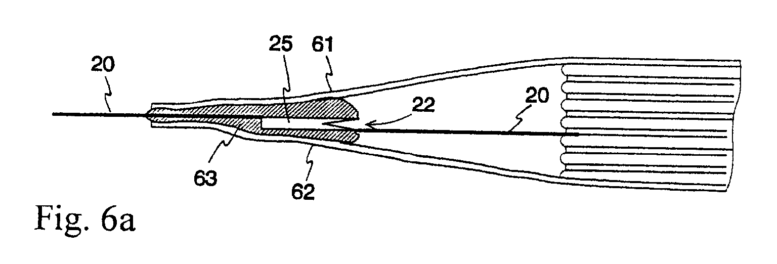
- Fig. 6a shows a longitudinal section of one end of a battery according to the invention.
- the battery employs at least one conductive strip 20 according to Fig. 2.
- the intermediate part 25 of the conductive strip 20, bent 180°, is viewed from the side.
- a slit 22 has been cut in the intermediate part 25.
- the battery shell has been sealed using a sealing compound 63.
- the sealing compound 63 also glues the first part of the conductive strip 20 to the top part 61 of the battery shell and the second part of the conductive strip 20 to the bottom part 62 of the battery shell.
- Fig. 6b shows the situation of the construction described above after the protection has worked. Misuse of battery has caused gas to be generated inside the battery, causing pressure which has bulged the battery shell.
- the first part of the conductive strip 20 attached to the top part of the battery shell has followed the top part of the shell upwards, and the second part of the conductive strip attached to the bottom part of the shell has followed the bottom part of the shell downwards.
- the conductive strip has been torn in two. Tear B starts at slit 22 because at that point a relatively small force suffices to break the conductive strip.
- the battery circuit is broken and gas generation ceases.
- Fig. 7 shows an example of the appearance of a battery according to the invention.
- the battery 70 comprises conductive strips 72 and 73 attached to electrodes and a flexible shell 71 which is hermetically sealed using a sealing compound.
Landscapes
- Chemical & Material Sciences (AREA)
- Chemical Kinetics & Catalysis (AREA)
- Electrochemistry (AREA)
- General Chemical & Material Sciences (AREA)
- Connection Of Batteries Or Terminals (AREA)
- Sealing Battery Cases Or Jackets (AREA)
Abstract
Description
- The invention relates to an arrangement defined in the preamble of claim 1 for preventing damage caused by a battery, and a battery defined in the preamble of
claim 10. - Misuse, such as overcharging, of a battery may result in generation of gas inside the battery and, hence, an increase in the internal pressure of the battery. The pressure may cause corrosive substances to spread outside the battery, resulting in damage to nearby circuits and equipment. In addition, misuse of the battery may result in a relatively dramatic build-up of thermal energy in the battery if electrical energy is no longer chemically absorbed. Accumulation of heat may also cause damage to structures around the battery.
- Misuse of a battery is usually prevented by means of a safety circuit in the charging device: The battery voltage is monitored, and when it has reached a predetermined level corresponding to full charge, the charging current is electronically switched off. The charging current is not switched back on until the battery voltage has dropped to a second level considerably lower than the first one. Such an external safety circuit by itself provides inadequate protection. The charging device may become faulty so that the protection will not work. Furthermore, the battery may be connected to a charging device of an incorrect type, or even the wrong way around by its terminals. Safe batteries therefore have got internal protection in case of misuse.
- From the prior art it is known internal battery protection methods as follows:
- Use of internal protective components: A positive temperature coefficient (PTC) thermal resistor is placed in the battery circuitry. When the charging current is too large or the battery heats up because of chemical reasons the resistance of the thermal resistor rises, causing the charging current to drop. A disadvantage with the use of a thermal resistor is the limited protection it offers: A slight overcharging state may persist for a long time. In addition, a thermal resistor increases energy consumption during normal operation of the battery. Similarly, a thermal fuse can be placed in the battery circuitry. As the temperature of the battery reaches a certain limit, the thermal fuse disconnects the charging circuit. A disadvantage with the use of a thermal fuse is the energy consumption caused by it during normal operation of the battery.
- Use of internal protective circuits: An electronic circuit is placed in the battery, sensing the battery current and voltage. If during the charging of the battery the behavior of the current or voltage deviates from the normal, said protective circuit disconnects the charging current. A disadvantage with the use of a protective circuit is that it increases the battery manufacturing costs. An additional disadvantage in this case, too, is that the energy consumption increases during normal operation of the battery.
- Use of gas hole or valve: A small hole is made on a battery cell or a valve is placed in it such that gas possibly generated inside the battery can exit the battery. This eliminates a considerable increase in pressure and spreading of chemicals outside the battery in cases of gross misuse. There is, however, the disadvantage of heat accumulation in the battery and structures around it if the overcharging state is prolonged.
- Mechanical disconnection of the charging circuit: Fig. 1 shows a breakable construction.
On one side of a
battery 10 there is afoil 11 made of a relatively thin conductive material. The battery charging circuit comprises athin conductor 12 attached to thefoil 11. The battery is hermetically sealed. If the battery is overcharged, the pressure of the gas generated distends thefoil 11 as shown in Fig. lc. As the pressure exceeds a certain threshold theconductor 12 breaks in two at point B and the charging current is disconnected. A disadvantage of the method is that it is only applicable to batteries which apart from said foil have a hard shell. - An object of the invention is to reduce said disadvantages related to the prior art. The protection method according to the invention is characterized by what is expressed in the
independent claims 1 and 10. Preferred embodiments of the invention are presented in the dependent claims. - The basic idea of the invention is as follows: A battery is manufactured such that pressure generated inside it will cause at least one of the battery's conductors to tear in two, thus interrupting the flow of current through said conductor. To that end, the battery shell is made at least partly of a flexible material and is hermetically sealed. Said conductors are thin strips and their strength, or at least the strength of one of them, is reduced at one point e.g. by cutting a slit on a side of the conductor. The conductive strip is attached at one side of said point to the upper portion of the battery shell and at the other side to the lower portion of the battery shell. If pressure is generated inside the battery because of misuse, the pressure will distend the battery shell and the upper and lower portions of the shell will tear the conductive strip in two. A relatively small amount of force will suffice to accomplish that because the "tearing" has been started in advance by making said slit.
- An advantage of the invention is that an increase in the internal pressure of a battery will not result in the spreading of corrosive chemicals outside the apparatus. Another advantage of the invention is that the charging of a battery is stopped before the battery will heat up its surroundings possibly to a damaging extent. A further advantage of the invention is that protection according to the invention will not cause extra energy consumption during normal operation of the battery. A yet further advantage of the invention is that it finds particular utility in batteries having a flexible construction; say, lithium polymer batteries, which are becoming more popular and for which there is no effective protection at the moment. Yet another advantage of the invention is that the costs of the arrangement according to the invention are relatively small. The costs are brought down among other things by the fact that the invention will make protective components redundant.
- The invention will now be described in more detail. Reference will be made to the accompanying drawing wherein
- Fig. 1
- shows a known conductor-breaking construction,
- Fig. 2
- shows an example of the conductive strip according to the invention,
- Fig. 3
- shows a second example of the conductive strip according to the invention,
- Fig. 4
- shows a third example of the conductive strip according to the invention,
- Fig. 5
- shows a fourth example of the conductive strip according to the invention,
- Fig. 6
- illustrates the behavior of the conductive strip according to Fig. 2 in overpressure,
- Fig. 7
- shows an example of the battery according to the invention.
- The construction in Fig. 1 and its operation were already discussed in conjunction with the description of the prior art.
- Fig. 2 shows an example of the conductive strip according to the invention. A
strip 20 having a width w at both ends has been cut from a thin metal sheet. The shape of the strip has a transition corresponding roughly to the width w as shown in Fig. 2a. Transition means that for the length d of thetransition area 21 the width of the strip is about 2w and that after thetransition area 21 the strip continues with the same width and direction as before the transition area but moved to the side for the width w. The strip portion corresponding to thetransition area 21 is divided into afirst part 23,second part 24 and a relatively narrowintermediate part 25 between the first and second parts. Theintermediate part 25 is located in the middle of thestrip 20 such that it divides the strip into two substantially rectangular parts. Fig. 2b shows a relativelysmall slit 22 cut in theintermediate part 25 of thestrip 20 such that the slit is parallel to the edge on the other side of the transition area. Naturally the slit can be cut at the same time that the strip itself is cut from the sheet. In Fig. 2c thestrip 20 has been bent 180° along the continuation of theslit 22 in theintermediate part 25 so that thefirst part 23 andsecond part 24 of the conductive strip have become placed one on top of the other. Theslit 22 is then located at the edge of the construction, parallel to the edge. Thestrip 20 is meant to be attached to the battery shell by its first and second parts. - Fig. 3 shows a second example of the conductive strip according to the invention. Fig. 3a shows a
transversal slit 32 at the edge of a straightconductive strip 30. Afirst part 33 of the conductive strip is located from theslit 32 and its imaginary continuation towards a first end of the conductive strip, and asecond part 34 is located towards a second end of the conductive strip. The upper surface of the first part and the lower surface of the second part are made coarse and the corresponding surfaces on the opposite sides of the conductive strip are made slippery as shown in Fig. 3b. The sealing compound on the battery shell sticks to the coarse surfaces considerably more tightly than to the slippery surfaces. Thus, thefirst part 33 is attached to the top part of the battery shell and thesecond part 34 to the bottom part of the battery shell. As the shell bulges, a moment is created in theconductive strip 30 the forces of which tear the conductive strip in two beginning at theslit 32. The "top part" and "bottom part" of the battery shell refer to the near-planar opposite halves of said shell. Similarly, the "upper surface" of the conductive strip or its part refers to said part's surface facing the top part of the battery shell, and the "lower surface" of the conductive strip or its part refers to said part's surface facing the bottom part of the battery shell. So, in the description and particularly in the claims, the top part and bottom part of the shell and the upper part and lower part of the conductive strip or its part are in no way related to the operating position of the battery. - Fig. 4 shows a third example of the conductive strip according to the invention. A
row 42 of relatively small perforations have been made transversally across a straightconductive strip 40. The spacing of perforations is so small that a force possibly directed to the battery shell by overpressure suffices to tear theconductive strip 40 in two. To attach thefirst part 43 of the conductive strip, saidpart 43 has aprotrusion 46 which is meant to be positioned inside or between the structures of the top part of the battery shell. Thesecond part 44 may of course have a similar protrusion. - Fig. 5 shows a fourth example of the conductive strip according to the invention. A
conductive strip 50 is bent 90° at two locations so that the ends of the conductive strip point to opposite directions. Between the bends there is a relatively narrowintermediate part 55. Aslit 52 has been made at the edge of the conductive strip in theintermediate part 55. Afirst part 53 of the conductive strip is located from theintermediate part 55 towards a first end of the conductive strip, and asecond part 54 of the conductive strip is located from theintermediate part 55 towards a second end of the conductive strip. - Fig. 6a shows a longitudinal section of one end of a battery according to the invention. The battery employs at least one
conductive strip 20 according to Fig. 2. Theintermediate part 25 of theconductive strip 20, bent 180°, is viewed from the side. Aslit 22 has been cut in theintermediate part 25. The battery shell has been sealed using a sealingcompound 63. The sealingcompound 63 also glues the first part of theconductive strip 20 to thetop part 61 of the battery shell and the second part of theconductive strip 20 to thebottom part 62 of the battery shell. - Fig. 6b shows the situation of the construction described above after the protection has worked. Misuse of battery has caused gas to be generated inside the battery, causing pressure which has bulged the battery shell. The first part of the
conductive strip 20 attached to the top part of the battery shell has followed the top part of the shell upwards, and the second part of the conductive strip attached to the bottom part of the shell has followed the bottom part of the shell downwards. As a consequence, the conductive strip has been torn in two. Tear B starts atslit 22 because at that point a relatively small force suffices to break the conductive strip. As the conductive strip is completely torn in two, the battery circuit is broken and gas generation ceases. The battery itself becomes dysfunctional but damage caused by overcharging or other misuse will be avoided. - Fig. 7 shows an example of the appearance of a battery according to the invention. The
battery 70 comprisesconductive strips flexible shell 71 which is hermetically sealed using a sealing compound. - Above it was described some techniques according to the invention for preventing disadvantages caused by the formation of pressure in a battery. The invention is not limited to the techniques described above. There are many structural approaches that can be used to reduce the strength of a conductive strip at a given point. In addition, each individual approach can be implemented in various ways, such as cutting, milling, sawing, pressing or etching. Similarly, the attachment of the parts of a conductive strip to the battery shell can be realized in many ways. The inventional idea can be applied in numerous ways within the scope defined by the claims set forth below.
Claims (9)
- An arrangement for preventing a battery from causing damages to its surroundings, comprising a conductive strip (20; 30; 40; 50) which includes a first portion (23; 33; 43; 53), a second portion (24; 34; 44; 54) and a portion (25; 55) between the first and second portions, characterized in thatthe battery is enclosed in a flexible and gastight battery shell comprising a top part and a bottom part,the strength of said conductive strip in the portion between the first and second portions is substantially smaller than in the first portion and second portion andthe arrangement also includes the attachment of the first portion to the top part (61) of said battery shell and the attachment of the second portion to the bottom part (62) of said battery shell.
- The arrangement of claim 1, characterized in that the first portion (23) and second portion (24) of the conductive strip are at least partly one on top of the other.
- The arrangement of claim 1, characterized in that the first portion (33; 43; 53) and second portion (34; 44; 54) of the conductive strip are located one after the other in the longitudinal direction of the conductive strip.
- A conductive strip according to claim 3, characterized in that those surfaces of the first and second portion that face the corresponding top and bottom parts of said battery shell are coarse, and their opposite surfaces are slippery.
- The arrangement of claim 1, characterized in that the strength of the conductive strip is reduced by means of a slit (22; 32; 52) on one side of the strip.
- The arrangement of claims 1, characterized in that the strength of the conductive strip is reduced by means of perforations (42) in the strip.
- The arrangement of claim 1, characterized in that the attachment of the first portion and second portion to the parts of said battery shell is based on gluing.
- The arrangement of claim 1, characterized in that the attachment of at least one portion (43) of the conductive strip to the corresponding part of said battery shell is based on a protrusion (46) on said portion, which protrusion reaches to the structures of said battery shell.
- A battery comprising a conductive strip and a flexible and gastight battery shell, characterized in that said conductive strip is arranged so as to be torn in two when the pressure difference between the inside and outside of said battery shell exceeds a predetermined limit.
Applications Claiming Priority (2)
| Application Number | Priority Date | Filing Date | Title |
|---|---|---|---|
| FI980962A FI980962L (en) | 1998-04-30 | 1998-04-30 | Arrangement for implementing protection in the battery and the battery |
| FI980962 | 1998-04-30 |
Publications (1)
| Publication Number | Publication Date |
|---|---|
| EP0961331A1 true EP0961331A1 (en) | 1999-12-01 |
Family
ID=8551625
Family Applications (1)
| Application Number | Title | Priority Date | Filing Date |
|---|---|---|---|
| EP99660067A Withdrawn EP0961331A1 (en) | 1998-04-30 | 1999-04-27 | Arrangement for implementing a safety feature in a battery, and a battery |
Country Status (3)
| Country | Link |
|---|---|
| US (1) | US6713209B1 (en) |
| EP (1) | EP0961331A1 (en) |
| FI (1) | FI980962L (en) |
Cited By (3)
| Publication number | Priority date | Publication date | Assignee | Title |
|---|---|---|---|---|
| CN107548524A (en) * | 2015-05-07 | 2018-01-05 | 株式会社Lg化学 | Pouch type secondary battery including electrode lead with current limiting function |
| EP3246966A4 (en) * | 2015-05-07 | 2018-09-26 | LG Chem, Ltd. | Pouch-type secondary battery including electrode lead having electrical current limiting function |
| EP3490036A4 (en) * | 2017-05-25 | 2019-07-31 | LG Chem, Ltd. | SECONDARY BATTERY AND METHOD FOR MANUFACTURING SUCH BATTERY SECONDARY |
Families Citing this family (7)
| Publication number | Priority date | Publication date | Assignee | Title |
|---|---|---|---|---|
| JP4720065B2 (en) * | 2001-09-04 | 2011-07-13 | 日本電気株式会社 | Film outer battery and battery pack |
| JP3789439B2 (en) * | 2003-03-03 | 2006-06-21 | Necラミリオンエナジー株式会社 | Film exterior laminated battery pack |
| KR101558709B1 (en) * | 2013-12-30 | 2015-10-08 | 현대자동차주식회사 | High voltage battery for vehicle |
| KR101704127B1 (en) * | 2014-11-14 | 2017-02-07 | 현대자동차주식회사 | Battery system improving operational reliability of swelling cid |
| KR101755861B1 (en) * | 2015-10-16 | 2017-07-07 | 현대자동차주식회사 | Battery Cell |
| KR101766047B1 (en) * | 2015-10-22 | 2017-08-07 | 현대자동차주식회사 | Battery Cell |
| KR102320114B1 (en) * | 2017-06-21 | 2021-11-01 | 주식회사 엘지화학 | Current interrupt structure applied to the pouch type secondary battery |
Citations (6)
| Publication number | Priority date | Publication date | Assignee | Title |
|---|---|---|---|---|
| US4633365A (en) * | 1985-03-05 | 1986-12-30 | American Radionic Co., Inc. | Metallized capacitor with protective interrupter device and method of making the same |
| JPS63237360A (en) * | 1987-03-26 | 1988-10-03 | Shin Kobe Electric Mach Co Ltd | Lithium cell |
| WO1994010712A1 (en) * | 1992-10-29 | 1994-05-11 | Valence Technology, Inc. | Battery packaging and interconnection scheme |
| JPH06215755A (en) * | 1993-01-18 | 1994-08-05 | Matsushita Electric Ind Co Ltd | Thin battery and manufacturing method thereof |
| US5609972A (en) * | 1996-03-04 | 1997-03-11 | Polystor Corporation | Cell cap assembly having frangible tab disconnect mechanism |
| EP0862230A2 (en) * | 1997-02-24 | 1998-09-02 | Mitsubishi Denki Kabushiki Kaisha | Thin battery |
Family Cites Families (3)
| Publication number | Priority date | Publication date | Assignee | Title |
|---|---|---|---|---|
| US4756983A (en) | 1987-11-23 | 1988-07-12 | Eveready Battery Company | Cell circuit interrupter |
| JPH0682546B2 (en) * | 1988-03-10 | 1994-10-19 | 松下電器産業株式会社 | Outer can and dry battery using the same |
| US5877564A (en) | 1997-02-18 | 1999-03-02 | Nokia Mobile Phones Limited | Mobile station voltage supply using level shift of base band operating voltages |
-
1998
- 1998-04-30 FI FI980962A patent/FI980962L/en unknown
-
1999
- 1999-04-27 EP EP99660067A patent/EP0961331A1/en not_active Withdrawn
- 1999-04-29 US US09/301,714 patent/US6713209B1/en not_active Expired - Lifetime
Patent Citations (6)
| Publication number | Priority date | Publication date | Assignee | Title |
|---|---|---|---|---|
| US4633365A (en) * | 1985-03-05 | 1986-12-30 | American Radionic Co., Inc. | Metallized capacitor with protective interrupter device and method of making the same |
| JPS63237360A (en) * | 1987-03-26 | 1988-10-03 | Shin Kobe Electric Mach Co Ltd | Lithium cell |
| WO1994010712A1 (en) * | 1992-10-29 | 1994-05-11 | Valence Technology, Inc. | Battery packaging and interconnection scheme |
| JPH06215755A (en) * | 1993-01-18 | 1994-08-05 | Matsushita Electric Ind Co Ltd | Thin battery and manufacturing method thereof |
| US5609972A (en) * | 1996-03-04 | 1997-03-11 | Polystor Corporation | Cell cap assembly having frangible tab disconnect mechanism |
| EP0862230A2 (en) * | 1997-02-24 | 1998-09-02 | Mitsubishi Denki Kabushiki Kaisha | Thin battery |
Non-Patent Citations (2)
| Title |
|---|
| PATENT ABSTRACTS OF JAPAN vol. 013, no. 038 (E - 709) 27 January 1989 (1989-01-27) * |
| PATENT ABSTRACTS OF JAPAN vol. 018, no. 573 (E - 1624) 2 November 1994 (1994-11-02) * |
Cited By (8)
| Publication number | Priority date | Publication date | Assignee | Title |
|---|---|---|---|---|
| CN107548524A (en) * | 2015-05-07 | 2018-01-05 | 株式会社Lg化学 | Pouch type secondary battery including electrode lead with current limiting function |
| JP2018511155A (en) * | 2015-05-07 | 2018-04-19 | エルジー・ケム・リミテッド | Pouch-type secondary battery including electrode lead with current limiting function |
| EP3246966A4 (en) * | 2015-05-07 | 2018-09-26 | LG Chem, Ltd. | Pouch-type secondary battery including electrode lead having electrical current limiting function |
| EP3276703B1 (en) * | 2015-05-07 | 2019-10-09 | LG Chem, Ltd. | Pouch-type secondary battery including electrode lead having current limiting function |
| US10665836B2 (en) | 2015-05-07 | 2020-05-26 | Lg Chem, Ltd. | Pouch-type secondary battery including electrode lead having current limiting function |
| US10741822B2 (en) | 2015-05-07 | 2020-08-11 | Lg Chem, Ltd. | Pouch-type secondary battery including electrode lead having electrical current limiting function |
| EP3490036A4 (en) * | 2017-05-25 | 2019-07-31 | LG Chem, Ltd. | SECONDARY BATTERY AND METHOD FOR MANUFACTURING SUCH BATTERY SECONDARY |
| US11031661B2 (en) | 2017-05-25 | 2021-06-08 | Lg Chem, Ltd. | Secondary battery and method for manufacturing the same |
Also Published As
| Publication number | Publication date |
|---|---|
| FI980962A7 (en) | 1999-10-31 |
| FI980962A0 (en) | 1998-04-30 |
| US6713209B1 (en) | 2004-03-30 |
| FI980962L (en) | 1999-10-31 |
Similar Documents
| Publication | Publication Date | Title |
|---|---|---|
| CN1319189C (en) | Non-aqueous electrolytic secondary battery | |
| US11228071B2 (en) | Battery cell for electric vehicle battery pack | |
| US11387068B2 (en) | Active/passive fuse module | |
| DE69733609T2 (en) | POWER INTERRUPTER FOR ELECTROCHEMICAL CELLS | |
| CN101479864B (en) | Secondary battery having electrodes with self-cutting sections that self-destruct when overcurrent is applied | |
| EP2180538B1 (en) | Protective circuit module and rechargeable battery including the same | |
| US6713209B1 (en) | Arrangement for implementing a safety feature in a battery | |
| CN101897056A (en) | PCM having improved assembling structure and battery pack using the same | |
| CA2562960A1 (en) | Electrochemical cell comprising electrode lead with protector element | |
| JP7676696B2 (en) | Active/Passive Fuse Modules | |
| KR19990087638A (en) | Battery cap assembly with malleable tab cutting mechanism | |
| US6391491B1 (en) | Lithium secondary battery having case with simplified safety device | |
| CN114696043A (en) | Battery pack | |
| EP1102338B1 (en) | Ptc element, ptc element-mounted pcb board, secondary cell protection circuit device and secondary cell assembly | |
| CN107871840A (en) | battery unit | |
| JP2008507248A (en) | Safety element for preventing overcharge of secondary battery and secondary battery having the safety element combined | |
| KR20060010659A (en) | Secondary protection element for secondary battery | |
| CN100359616C (en) | Direct current cutoff switch | |
| JPH10188946A (en) | Prismatic battery with internal short-circuit protection device | |
| CA2439860A1 (en) | Connection device for an electric accumulator | |
| US11594391B2 (en) | Active/passive fuse module | |
| KR20170031063A (en) | Battery system with an overcharge protection and/or deep discharge protection | |
| JP2001067997A (en) | Semiconductor switch | |
| JP4890694B2 (en) | Polymer PTC thermistor | |
| KR960010104B1 (en) | Protected potted metallized film capacitor |
Legal Events
| Date | Code | Title | Description |
|---|---|---|---|
| PUAI | Public reference made under article 153(3) epc to a published international application that has entered the european phase |
Free format text: ORIGINAL CODE: 0009012 |
|
| AK | Designated contracting states |
Kind code of ref document: A1 Designated state(s): DE FR GB IT |
|
| AX | Request for extension of the european patent |
Free format text: AL;LT;LV;MK;RO;SI |
|
| 17P | Request for examination filed |
Effective date: 20000505 |
|
| AKX | Designation fees paid |
Free format text: DE FR GB IT |
|
| 17Q | First examination report despatched |
Effective date: 20010509 |
|
| RAP1 | Party data changed (applicant data changed or rights of an application transferred) |
Owner name: NOKIA CORPORATION |
|
| GRAH | Despatch of communication of intention to grant a patent |
Free format text: ORIGINAL CODE: EPIDOS IGRA |
|
| STAA | Information on the status of an ep patent application or granted ep patent |
Free format text: STATUS: THE APPLICATION IS DEEMED TO BE WITHDRAWN |
|
| 18D | Application deemed to be withdrawn |
Effective date: 20030805 |