EP0961106A1 - Device for measuring the filling-level of a container - Google Patents
Device for measuring the filling-level of a container Download PDFInfo
- Publication number
- EP0961106A1 EP0961106A1 EP99117849A EP99117849A EP0961106A1 EP 0961106 A1 EP0961106 A1 EP 0961106A1 EP 99117849 A EP99117849 A EP 99117849A EP 99117849 A EP99117849 A EP 99117849A EP 0961106 A1 EP0961106 A1 EP 0961106A1
- Authority
- EP
- European Patent Office
- Prior art keywords
- level
- limit
- measuring device
- echo
- container
- Prior art date
- Legal status (The legal status is an assumption and is not a legal conclusion. Google has not performed a legal analysis and makes no representation as to the accuracy of the status listed.)
- Ceased
Links
Images


Classifications
-
- G—PHYSICS
- G01—MEASURING; TESTING
- G01F—MEASURING VOLUME, VOLUME FLOW, MASS FLOW OR LIQUID LEVEL; METERING BY VOLUME
- G01F23/00—Indicating or measuring liquid level or level of fluent solid material, e.g. indicating in terms of volume or indicating by means of an alarm
- G01F23/22—Indicating or measuring liquid level or level of fluent solid material, e.g. indicating in terms of volume or indicating by means of an alarm by measuring physical variables, other than linear dimensions, pressure or weight, dependent on the level to be measured, e.g. by difference of heat transfer of steam or water
- G01F23/28—Indicating or measuring liquid level or level of fluent solid material, e.g. indicating in terms of volume or indicating by means of an alarm by measuring physical variables, other than linear dimensions, pressure or weight, dependent on the level to be measured, e.g. by difference of heat transfer of steam or water by measuring the variations of parameters of electromagnetic or acoustic waves applied directly to the liquid or fluent solid material
- G01F23/284—Electromagnetic waves
-
- G—PHYSICS
- G01—MEASURING; TESTING
- G01F—MEASURING VOLUME, VOLUME FLOW, MASS FLOW OR LIQUID LEVEL; METERING BY VOLUME
- G01F25/00—Testing or calibration of apparatus for measuring volume, volume flow or liquid level or for metering by volume
- G01F25/20—Testing or calibration of apparatus for measuring volume, volume flow or liquid level or for metering by volume of apparatus for measuring liquid level
- G01F25/24—Testing proper functioning of electronic circuits
-
- G—PHYSICS
- G01—MEASURING; TESTING
- G01F—MEASURING VOLUME, VOLUME FLOW, MASS FLOW OR LIQUID LEVEL; METERING BY VOLUME
- G01F23/00—Indicating or measuring liquid level or level of fluent solid material, e.g. indicating in terms of volume or indicating by means of an alarm
- G01F23/22—Indicating or measuring liquid level or level of fluent solid material, e.g. indicating in terms of volume or indicating by means of an alarm by measuring physical variables, other than linear dimensions, pressure or weight, dependent on the level to be measured, e.g. by difference of heat transfer of steam or water
- G01F23/28—Indicating or measuring liquid level or level of fluent solid material, e.g. indicating in terms of volume or indicating by means of an alarm by measuring physical variables, other than linear dimensions, pressure or weight, dependent on the level to be measured, e.g. by difference of heat transfer of steam or water by measuring the variations of parameters of electromagnetic or acoustic waves applied directly to the liquid or fluent solid material
- G01F23/296—Acoustic waves
- G01F23/2962—Measuring transit time of reflected waves
-
- Y—GENERAL TAGGING OF NEW TECHNOLOGICAL DEVELOPMENTS; GENERAL TAGGING OF CROSS-SECTIONAL TECHNOLOGIES SPANNING OVER SEVERAL SECTIONS OF THE IPC; TECHNICAL SUBJECTS COVERED BY FORMER USPC CROSS-REFERENCE ART COLLECTIONS [XRACs] AND DIGESTS
- Y10—TECHNICAL SUBJECTS COVERED BY FORMER USPC
- Y10S—TECHNICAL SUBJECTS COVERED BY FORMER USPC CROSS-REFERENCE ART COLLECTIONS [XRACs] AND DIGESTS
- Y10S367/00—Communications, electrical: acoustic wave systems and devices
- Y10S367/908—Material level detection, e.g. liquid level
Definitions
- the invention relates to a level measuring device for measuring the level of a product in a container.
- Level measuring devices which at any time a measurement of the current level in the Containers can deliver
- limit switches which only indicate whether the Level in the tank above or below one of the limit switches monitoring predetermined height.
- Such limiters will be used in particular to get a maximum or minimum level monitor to avoid overfilling or underfilling the container.
- limit transmitters for example capacitive or resistive limit switches based on electrical properties address the product, limit switch with vibrating elements, such as Membranes or vibrating rods, whose vibrations are caused by the filling material are damped or their natural resonance frequency by the product is changed, etc.
- the choice of the limit transmitter used depends on the properties of the product and the conditions of use.
- a limit transmitter emits an electrical signal that is a first signal value if the level is below the monitored level and has a different second signal value if the Level is above the level to be monitored.
- the signal changes its Signal value if and when the filling material is added or removed Level goes through the height to be monitored.
- the signal value depends on whether the limit switch with the product is in contact or not; with such limiters corresponds to the predetermined level of the level that the limit indicator monitors the installation height of the limit indicator.
- DE 39 04 824 A1 describes a fill level measuring arrangement which on the one hand a mechanical level measuring device, e.g. with float operated Transmission linkage, for continuous level measurement in a container and on the other hand an electrical limit switch Limitation of the maximum permissible level. If the level the maximum permissible height is reached, the limit indicator gives an electrical one Signal that is independent of that of the mechanical level meter displayed level an electronically controlled automatic level limit triggers, for example filling the container interrupts. In this way, overfilling of the container will also occur a defect or inaccuracy of the mechanical level measuring device prevented.
- a mechanical level measuring device e.g. with float operated Transmission linkage
- a measuring circuit calculates the height of the liquid from the Ratio of the difference between the arrival times of those of the two top immersed reflectors reflected ultrasonic pulses and the Difference between the arrival times of the from the liquid surface and ultrasound pulses reflected from the top immersed reflector.
- the measurement is independent of changes in acoustic Properties within the liquid, especially material or temperature-related changes in the speed of sound.
- the usage on the one hand results in a bundling of the sound waves onto one small area of the liquid surface and on the other hand prevents the Influence of interference reflections and external sources of interference.
- This known technique requires a tube in the container is attached, which extends essentially over the entire height of the container extends. This is the case with small containers, such as fuel tanks in vehicles or aircraft, possible without problems, but proves to be the case with large containers often as difficult or impossible.
- the known technology also requires that the transceiver for the runtime measurement used shafts attached to the lower end of the tube and thus the Liquid in the container are exposed, for example when aggressive or very hot filling goods is not possible.
- the well-known Technology advance that the waves are transmitted through the liquid, what in many cases only possible when using ultrasound waves, not however, when using very short electromagnetic waves (Microwaves), as increasingly used for level measurement the runtime method can be used.
- a prerequisite for a correct level measurement with this procedure is that the useful echo from the total of the received echo waves is clearly identified.
- the received echo waves show the amplitudes as a function of distance forming echo function. Under ideal conditions, this shows Echo function to an absolute maximum, the position of which is the useful echo and thus the distance between the level measuring device and the Product surface represented. In practice, however, faults occur that complicate the evaluation of the echo function or even make it impossible. First of all, the noise background in the near area is significantly increased.
- Ultrasound equipment relies on the swinging out of the electroacoustic Converter, for microwave devices on multiple reflections in the range of Signal feed and the antenna.
- echoes are not only on the Product surface created, but also on other reflective structures in the beam path. Especially when measuring the level in containers due to reflections on container walls, welds and internals such as pipes, heating elements, limit switches etc. significant false echoes in the echo function, from which the useful echo must be distinguished. In particular, you can not assume that the useful echo with the absolute maximum of the echo function is identical.
- the invention has for its object in an arrangement for a continuous measurement of the level in a container after the Runtime procedure regardless of the size of the container and the type and the properties of the product is suitable, an automatic control of the Measurement result and, if necessary, the correction of a measurement error enable.
- the level measuring device has a Level sensor that is from one above the highest Occurring fill level from waves on the surface of the Product that directs the echo waves reflected on the product surface receives and an electrical output signal representing the echo waves provides, and which has a measuring circuit, which from the output signal of the level sensor that is reflected on the product surface Useful echo is determined and the measured value of the fill level from the running time of the Usable echoes determined, the measuring circuit using a two-wire line a remote evaluation point is connected, the measuring circuit via the two-wire line the electrical measuring signal indicating the level delivers and wherein the supply of the level with electrical Energy is supplied via the same two-wire line from the evaluation point.
- the measuring signal is a between 4 and 20 mA variable current signal; the waves are either around short electromagnetic waves (microwaves) or around Ultrasonic waves.
- Filling level measuring device is at least one limit transmitter on the container arranged, which provides an electrical signal that indicates whether the level in the container larger or smaller than one from the limit transmitter too monitoring level is between the minimum and the maximum fill level of the container is; the measuring circuit receives this Output signal of the or each limit transmitter and uses it for Check the level measurement value determined by the level measuring device.
- each limit transmitter delivers whenever the level in the container changes, an exact one each time Level measured value, if the level just equal to that of the Limit transmitter to be monitored height.
- Measured value By comparing this Measured value with that simultaneously supplied by the level measuring device Measured value can be determined whether there is a measurement error, and at If a predetermined error limit is exceeded, measures for Correction of the measurement error can be initiated or there may be a warning or error message are issued.
- a first embodiment of the invention is that on the container several limit switches for monitoring different heights of the Level are arranged and the measuring circuit at each Change in state of the output signal of a limit indicator that occurs if the level is the level to be monitored by this limit indicator reached, the level measurement value supplied simultaneously by the level measuring device with this height compares to the correctness of the Check the level measuring device.
- the measuring circuit from the output signal of the level sensor Echo function that forms the echo amplitudes as a function of distance represents the entire measuring range, and each current echo function with a stored empty echo function when the container is empty compares in order to determine the useful echo, that on the product surface corresponds to reflected echo waves
- the arrangement is in this case preferably designed so that the measuring circuit each time the Height comparison one above a specified error limit Measurement error results, the empty echo function is updated from the top to the height, which is to be monitored by the limit transmitter, its output signal changed its state.
- the Measuring circuit the stored empty echo function regardless of the Result of the height comparison every time the output signal a limit transmitter changes its state, from top to that of updated the level to be monitored by this limit indicator.
- Another embodiment of this first embodiment is that the measuring circuit the stored empty echo function in predetermined Time intervals in the area of the limit switches, their output signals indicate that the level is below the heights to be monitored lies, updated.
- the measuring circuit for determining the Useful echoes only evaluate the part of the current echo function that is in the Range between the heights to be monitored by two limit switches is one of which a limit indicator indicates that the level is above the of the height to be monitored, and the other limit transmitter indicates that the level is below the level to be monitored.
- the measuring circuit checks whether the Level measuring device delivered level measuring value in the range between the heights to be monitored by two limit switches, of which which a limit transmitter emits a signal that indicates that the level is above the level to be monitored, and the other Limit transmitter emits a signal that indicates that the level is below the height to be monitored by him.
- a second embodiment of the invention is that on the container a limit switch is arranged and the measuring circuit at each Change in state of the output signal of the limit indicator that occurs if the level is the level to be monitored by the limit indicator reached, the level measurement value supplied simultaneously by the level measuring device with this height compares to the correctness of the Check the level measuring device.
- the measuring circuit from the output signal of the level sensor Echo function that forms the echo amplitudes as a function of distance represents the entire measuring range, and each current echo function with a stored empty echo function when the container is empty compares in order to determine the useful echo, that on the product surface corresponds to reflected echo waves
- the arrangement is in this case preferably designed so that the measuring circuit each time the Height comparison one above a specified error limit Measurement error results, the empty echo function is updated from the top to the height, which is to be monitored by the limit transmitter.
- the Measuring circuit the stored empty echo function regardless of the Result of the height comparison every time the output signal of the Limit switch changes its state, from the top to that of Limit transmitter for monitored height updated.
- Fig. 1 of the drawing shows a container 10, partially with a filling 12 is filled.
- the container has an inlet 14 for introducing filling material in the container and with an outlet 16 for removing filling material from the Provide container.
- the container can be used with others, the expert known devices to be equipped, depending on the type of product depend, for example with a motor-driven stirrer 18th
- the level F is the height of the product surface 19 above the lowest point of the container. This level changes when the product is fed into the Container and when filling material is removed from the container.
- a fill level measuring device 20 is attached to the container above the highest occurring fill level and operates according to the running time.
- the fill level measuring device 20 contains a fill level sensor 22, which emits waves towards the fill surface 19 and receives the echo waves reflected on the fill surface 19, and an electronic measuring circuit 24, which is accommodated in a housing 26 mounted on the top of the container, and electrical signals from the fill level sensor 22 receives.
- the measuring circuit 24 is connected via a two-wire line 28 to a remote one Evaluation point connected; it delivers a via the two-wire line 28 Level-indicating electrical measurement signal according to a known For example, a current signal that varies between 4 and 20 mA is standard can be.
- the measurement signal for displaying the Fill level are used, as well as to trigger switching operations For example, regulate the filling and emptying of the container 10.
- About the same two-wire line can supply according to a known technique the level measuring device 20 with electrical energy from the evaluation point done here.
- the Runtime method has the advantage that the level sensor 22 with the Product 12 does not have to come into direct contact.
- the bets can be very be short electromagnetic waves (microwaves) or ultrasonic waves. In in most cases the waves are emitted in the form of short pulses, so that the echo waves received also take the form of short impulses; it however, runtime methods are also known which are based on the Continuous wave method work with continuously emitted waves.
- the structure of the level sensor 22 naturally depends on the type of used waves.
- the level sensor 22 contains one Transmitting generator, the electrical vibrations with the frequency of Generates transmission waves that are fed to the horn 30, and a Receiving circuit that matches the received echo waves with the same Frequency amplified.
- One for sending and receiving ultrasonic waves certain level sensor would be an electroacoustic transducer for converting the electrical transmission signal into ultrasonic waves and for Have radiation of these ultrasonic waves and the same or one similar converter for converting the received ultrasonic echo waves use in an electrical receive signal. Since the mentioned Components of such level sensors are generally known to the person skilled in the art are, they are not shown in the drawing, and they do not need further to be described.
- the echo amplitudes as a function the echo function representing the distance.
- this echo function has a clear absolute maximum on whose position is the distance D between the level measuring device and represents the product surface.
- FIG. 2 Such an ideal echo function is shown in FIG. 2, in which there is only one significant peak N above an existing noise level R and can be clearly identified as a useful peak.
- N an existing noise level
- R an existing noise level
- Such a real echo function E is shown in FIG. 3.
- a sloping ramp A extends up to 2 m; at 2.5 m and at 3.3 m there are false echoes S1, S2, which are caused by internals.
- the useful echo N at 7 m is both smaller than the false echo S1 at 2.5 m as also smaller than noise peaks on ramp A.
- the useful echo N is therefore not identical to the main maximum of the echo function here.
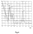
- a limit curve G can be defined by adding a constant to the empty echo function.
- the current echo function E differs from the empty echo function in front area not. Only the peaks are from the current echo function evaluated that lie above the limit curve G. In the example shown this only applies to the useful peak N at 7 m.
- the problem shown in Fig. 1 shown container 10 in addition to the level measuring device 20 four Limit switches 32, 34, 36, 38 attached at different heights.
- the limit value transmitter is a device which emits an electrical signal, this indicates whether the level in the container has reached a predetermined level or not.
- Different types of limit switches are known, for example capacitive and resistive limit switches based on electrical Address the properties of the medium, limit switches with vibrating Elements, such as membranes or vibrating rods, whose vibrations are caused by the contents are damped or their natural resonance frequency by the Filling material is changed, etc.
- limit switches are used used to reach a critical fill level in the container monitor, for example a maximum level that is not may be exceeded, or a minimum fill level that does not may fall below.
- the choice of each used Limit transmitter depends on the properties of the product and the Conditions of use.
- a limit sensor enters electrical signal that has a first signal value when the level is below the altitude to be monitored, and one that is different has second signal value when the level is above the monitored level lies. The signal changes its signal value exactly when it is fed or removal of the filling level from the level to be monitored goes.
- the signal value depends on several types of limit switches whether the limit indicator is in contact with the product or not; at such limit sensors correspond to the predetermined level of the fill level, which the limit switch monitors, the installation height of the limit switch.
- Each of the limit switches 32, 34, 36, 38 shown in FIG. 1 is known Suitable type; Of course, the type of limit switch is also selected here, which is best suited for the product 12 in question. For the better Understanding is assumed below that it is a limit transmitter where the signal value of the output signal depends on whether the limit indicator is in contact with the product or not. Have so at the level F shown, the output signals of the two upper limit transmitter 32 and 34 the first signal value because this Limit switches are not in contact with the filling material 12 while the Output signals of the two lower limit switches 36 and 38 the second Have signal value because these limit switches in contact with the product 12 stand.
- Each limit transmitter is via its own line 33, 35, 37 and 39 connected to the measuring circuit 24 of the level measuring device 20, so that this measuring circuit receives the output signals of the four limit switches and in the manner described below for interference suppression, Plausibility check and self-correction in the case of the level measuring device 20 carried out continuous level measurement can evaluate.
- the measuring circuit 24 can perform a plausibility check at any time the level measurement value supplied by the level measuring device 20 using the Carry out the instantaneous output signals of the sensors 32 to 38.
- the fill level F lies between the height to be monitored by the limit transmitter 34 and that by Limit transmitter 36 height to be monitored.
- the measuring circuit 24 recognizes this state from the fact that the output signal of the limit switch 34 the first signal value and the output signal of the limit transmitter 36 den has second signal value.
- the measured value supplied by the level measuring device 20 must therefore lie between these two heights; if not, so the measuring circuit 24 recognizes that there is a measuring error.
- the output signals which are always present can also be present in the measuring circuit 24 the limit transmitter 32 to 38 when evaluating the from Fill level measuring device delivered received signals are used to especially under difficult measuring conditions facilitate and increase error safety. Because from the output signals the limit switch 34 and 36 is known that the level lies between the heights assigned to these limit transmitters, the Evaluation of the part of the echo function originating from this area be restricted. This would, for example, in this level 3 the noise jags of ramp A and the Interference peaks S1 and S2 are excluded from the evaluation from the outset, whereby any danger would be avoided that one of these rags or Interference peaks is mistakenly interpreted as a useful peak.
- limit switches 32 to 38 still provide information to a significant extent more precise level information whenever changes to the Fill level whose level just by that of a limit switch too monitoring height goes so that the relevant limit switch "switches" and its output signal changes its signal value.
- the instantaneous measured value supplied by the level measuring device 20 can be checked whether the level meter 20 is working properly. If the difference a predetermined tolerance threshold between the two measured values exceeds, the level meter 20 can automatically the following Take measures to improve its function:
- the empty echo function of the container is from the top to the height of the switching limit transmitter updated, and there will be a corresponding new limit curve created. This changes the interference signals compensated. Deciding which of the peaks of the echo function does that If it is used, it becomes clear and correct again. A random one or periodically updating the empty echo function up to that of Level measuring device 20 alone without the aid of a limit indicator determined level would not be useful, since this level would be wrong can, for example, if a large Interference peak has formed, which is incorrectly evaluated as a useful peak. By updating the empty echo function up to that of one switching limit indicator displayed height is just such Interference peak suppressed.
- the measuring circuit 24 can the above described functions without significant modification of the hardware make appropriate program changes. They are only suitable Interfaces for the supply of the output signals of the limit switches required. These interfaces are problem-free for the specialist realizable, since these output signals are binary signals anyway accept one or the other of two signal values. Because such Circuits and their programming are generally known to the person skilled in the art detailed description and description is not required.
- the number of limit transmitters to be attached to the container the control of the continuously measuring level in sufficiently short time intervals can be carried out depends on the prevailing operating conditions. If the container is in itself frequently repetitive cycles essentially completely filled and again is emptied, such as in the chemical industry and in the Food industry is mostly the case, only one can Limit switch for performing all the functions described above are enough. In this case, it is important that the limit transmitter has a height of the level monitored when filling and emptying the container is regularly exceeded or undershot.
- FIG Level measuring arrangement of Fig. 1 shows a modified embodiment of FIG Level measuring arrangement of Fig. 1, in which only a single limit transmitter 40 about halfway up the container 10, i.e. in the middle between the minimum and maximum level is arranged.
- the measuring circuit In this case, 24 receives the output signal of the only one Limit transmitter 40 for the control of the level measuring device 20th carried out continuous level measurement.
- a permanent plausibility check is possible: If the limit transmitter 40 indicates that the level is above or below the level to be monitored Height, the level measurement value supplied by the level measurement device 20 must also are in the area in question. Furthermore, the Limit transmitter twice an exact level measurement value in each operating cycle, if the level when filling and emptying the container through the monitored height.
- the measured value supplied by the level measuring device 20 can be in be checked in the same way as in the embodiment of FIG. 1 whether the level gauge 20 is working properly, and it can be the previously measures described to remedy measurement errors or to display a malfunction.
Abstract
Description
Die Erfindung betrifft ein Füllstandsmeßgerät zur Messung des Füllstands eines Füllguts in einem Behälter.The invention relates to a level measuring device for measuring the level of a product in a container.
Bei der Füllstandsmessung unterscheidet man kontinuierlich messende Füllstandsmeßgeräte, die jederzeit einen Meßwert des aktuellen Füllstands im Behälter liefern können, und Grenzwertgeber, die lediglich anzeigen, ob der Füllstand im Behälter über oder unter einer von dem Grenzwertgeber zu überwachenden vorbestimmten Höhe liegt. Solche Grenzwertgeber werden insbesondere dazu verwendet, einen maximalen oder minimalen Füllstand zu überwachen, um ein Über- oder Unterfüllen des Behälters zu vermeiden. Es sind verschiedene Arten von Grenzwertgebern bekannt, beispielsweise kapazitive oder resistive Grenzwertgeber, die auf elektrische Eigenschaften des Füllguts ansprechen, Grenzwertgeber mit schwingenden Elementen, wie Membranen oder Schwingstäben, deren Schwingungen durch das Füllgut gedämpft werden oder deren Eigenresonanzfrequenz durch das Füllgut verändert wird, usw. Die Wahl des verwendeten Grenzwertgebers hängt von den Eigenschaften des Füllguts und von den Anwendungsbedingungen ab. In jedem Fall gibt ein Grenzwertgeber ein elektrisches Signal ab, das einen ersten Signalwert hat, wenn der Füllstand unter der zu überwachenden Höhe liegt, und das einen davon verschiedenen zweiten Signalwert hat, wenn der Füllstand über der zu überwachenden Höhe liegt. Das Signal ändert seinen Signalwert genau dann, wenn bei Zuführung oder Entnahme von Füllgut der Füllstand durch die zu überwachende Höhe geht. Bei mehreren Arten von Grenzwertgebern hängt der Signalwert davon ab, ob der Grenzwertgeber mit dem Füllgut in Berührung steht oder nicht; bei solchen Grenzwertgebern entspricht die vorbestimmte Höhe des Füllstands, die der Grenzwertgeber überwacht, der Einbauhöhe des Grenzwertgebers.In level measurement, a distinction is made between continuous measurements Level measuring devices, which at any time a measurement of the current level in the Containers can deliver, and limit switches, which only indicate whether the Level in the tank above or below one of the limit switches monitoring predetermined height. Such limiters will be used in particular to get a maximum or minimum level monitor to avoid overfilling or underfilling the container. It different types of limit transmitters are known, for example capacitive or resistive limit switches based on electrical properties address the product, limit switch with vibrating elements, such as Membranes or vibrating rods, whose vibrations are caused by the filling material are damped or their natural resonance frequency by the product is changed, etc. The choice of the limit transmitter used depends on the properties of the product and the conditions of use. In In any case, a limit transmitter emits an electrical signal that is a first signal value if the level is below the monitored level and has a different second signal value if the Level is above the level to be monitored. The signal changes its Signal value if and when the filling material is added or removed Level goes through the height to be monitored. With several types of Limit switches, the signal value depends on whether the limit switch with the product is in contact or not; with such limiters corresponds to the predetermined level of the level that the limit indicator monitors the installation height of the limit indicator.
In der DE 39 04 824 A1 ist eine Füllstandsmeßanordnung beschrieben, die einerseits ein mechanisches Füllstandsmeßgerät, z.B. mit schwimmerbetätigtem Übertragungsgestänge, zur kontinuierlichen Messung des Füllstands in einem Behälter und andererseits einen elektrischen Grenzwertgeber zur Begrenzung des maximal zulässigen Füllstands aufweist. Wenn der Füllstand die maximal zulässige Höhe erreicht, gibt der Grenzwertgeber ein elektrisches Signal ab, das unabhängig von dem vom mechanischen Füllstandsmeßgerät angezeigten Füllstand eine elektronisch gesteuerte automatische Füllstandsbegrenzung auslöst, also beispielsweise eine Befüllung des Behälters unterbricht. Auf diese Weise wird eine Überfüllung des Behälters auch im Fall eines Defekts oder einer Ungenauigkeit des mechanischen Füllstandsmeßgeräts verhindert.DE 39 04 824 A1 describes a fill level measuring arrangement which on the one hand a mechanical level measuring device, e.g. with float operated Transmission linkage, for continuous level measurement in a container and on the other hand an electrical limit switch Limitation of the maximum permissible level. If the level the maximum permissible height is reached, the limit indicator gives an electrical one Signal that is independent of that of the mechanical level meter displayed level an electronically controlled automatic level limit triggers, for example filling the container interrupts. In this way, overfilling of the container will also occur a defect or inaccuracy of the mechanical level measuring device prevented.
Andererseits sind kontinuierlich messende Füllstandsmeßgeräte bekannt, die nach dem Laufzeitverfahren arbeitende Abstandsmeßgeräte sind. So ist in der DE 43 07 635 A1 eine Vorrichtung zur kontinuierlichen Messung des Füllstands einer Flüssigkeit in einem Behälter beschrieben, die ein Rohr aufweist, das sich vom Boden des Behälters nach oben erstreckt und mit Flüssigkeit gefüllt ist, wobei der Füllstand innerhalb des Rohres mit dem Füllstand außerhalb des Rohres identisch ist. Entlang der Länge des Rohres sind eine Vielzahl von Reflektoren angebracht. Am unteren Ende des Rohres ist eine Sende-Empfangs-Einrichtung angebracht, die Ultraschallwellen nach oben durch die im Rohr befindliche Flüssigkeit abstrahlt und die an den Reflektoren und an der Flüssigkeitsoberfläche reflektierten Ultraschallwellen empfängt. Eine Meßschaltung berechnet die Höhe der Flüssigkeit aus dem Verhältnis der Differenz zwischen den Ankunftszeiten der von den beiden obersten eingetauchten Reflektoren reflektierten Ultraschallimpulse und der Differenz zwischen den Ankunftszeiten der von der Flüssigkeitsoberfläche und dem obersten eingetauchten Reflektor reflektierten Ultraschallimpulse. Auf diese Weise ist die Messung unabhängig von Änderungen der akustischen Eigenschaften innerhalb der Flüssigkeit, insbesondere von material- oder temperaturbedingten Änderungen der Schallgeschwindigkeit. Die Verwendung eines Rohres ergibt einerseits eine Bündelung der Schallwellen auf einen kleinen Bereich der Flüssigkeitsoberfläche und verhindert andererseits den Einfluß von Störreflexionen und von äußeren Störquellen.On the other hand, continuously measuring level gauges are known are distance measuring devices working according to the transit time method. So is in the DE 43 07 635 A1 a device for the continuous measurement of the Level of a liquid described in a container holding a pipe has, which extends from the bottom of the container upwards and with Liquid is filled, the level within the tube with the Level outside the tube is identical. Along the length of the pipe a variety of reflectors are attached. At the bottom of the tube a transceiver is attached to the ultrasonic waves after radiates at the top through the liquid in the tube and at the Reflectors and ultrasonic waves reflected on the liquid surface receives. A measuring circuit calculates the height of the liquid from the Ratio of the difference between the arrival times of those of the two top immersed reflectors reflected ultrasonic pulses and the Difference between the arrival times of the from the liquid surface and ultrasound pulses reflected from the top immersed reflector. On in this way the measurement is independent of changes in acoustic Properties within the liquid, especially material or temperature-related changes in the speed of sound. The usage on the one hand results in a bundling of the sound waves onto one small area of the liquid surface and on the other hand prevents the Influence of interference reflections and external sources of interference.
In sehr ähnlicher Weise ist eine in der DE 41 26 063 A1 beschriebene Füllstandsmeßvorrichtung ausgebildet, jedoch mit dem Unterschied, daß zwei parallele Rohre vorgesehen sind, von denen das eine Rohr die Reflektoren enthält, während das andere Rohr für die Laufzeitmessung zur Flüssigkeitsoberfläche verwendet wird; jedes der beiden Rohre ist mit einer eigenen Sende-Empfangs-Einrichtung für Ultraschallwellen versehen.A very similar way is one described in DE 41 26 063 A1 Level measuring device formed, but with the difference that two parallel tubes are provided, of which one tube is the reflectors contains, while the other tube for the runtime measurement for Liquid surface is used; each of the two tubes is with one provided its own transceiver for ultrasonic waves.
Diese bekannte Technik setzt voraus, daß in dem Behälter ein Rohr angebracht ist, das sich im wesentlichen über die ganze Höhe des Behälters erstreckt. Dies ist bei kleinen Behältern, wie Treibstofftanks in Fahrzeugen oder Flugzeugen, problemlos möglich, erweist sich aber bei großen Behältern oft als schwierig oder unmöglich. Die bekannte Technik setzt ferner voraus, daß die Sende-Empfangs-Einrichtungen für die zur Laufzeitmessung verwendeten Wellen am unteren Ende des Rohres angebracht und somit der Flüssigkeit im Behälter ausgesetzt sind, was beispielsweise bei aggressiven oder sehr heißen Füllgütern nicht möglich ist. Schließlich setzt die bekannte Technik voraus, daß die Wellen durch die Flüssigkeit übertragen werden, was in vielen Fällen nur bei Anwendung von Ultraschallwellen möglich ist, nicht jedoch bei Anwendung von sehr kurzen elektromagnetischen Wellen (Mikrowellen), wie sie in zunehmendem Maße zur Füllstandsmessung nach dem Laufzeitverfahren verwendet werden. This known technique requires a tube in the container is attached, which extends essentially over the entire height of the container extends. This is the case with small containers, such as fuel tanks in vehicles or aircraft, possible without problems, but proves to be the case with large containers often as difficult or impossible. The known technology also requires that the transceiver for the runtime measurement used shafts attached to the lower end of the tube and thus the Liquid in the container are exposed, for example when aggressive or very hot filling goods is not possible. Finally, the well-known Technology advance that the waves are transmitted through the liquid, what in many cases only possible when using ultrasound waves, not however, when using very short electromagnetic waves (Microwaves), as increasingly used for level measurement the runtime method can be used.
Die Schwierigkeiten, die bei der zuvor geschilderten bekannten Technik
auftreten, werden bei einem beispielsweise in der DE 38 12 293 C2
beschriebenen Füllstandsmeßgerät vermieden, das gleichfalls nach dem
Laufzeitverfahren arbeitet, wobei aber die Wellen von einer oberhalb des
höchsten vorkommenden Füllstands liegenden Stelle nach unten auf die
Oberfläche des Füllguts gerichtet werden. In diesem Fall gehen sowohl die
gesendeten Wellen als auch die reflektierten Echowellen nicht durch das
Füllgut, sondern durch die über dem Füllgut befindliche Luft, und die Sende-Empfangs-Einrichtung
steht nicht in direktem Kontakt mit dem Füllgut. Die zur
Laufzeitmessung verwendeten Wellen können Mikrowellen oder
Ultraschallwellen sein. In beiden Fällen ergibt sich der Abstand zwischen dem
Füllstandsmeßgerät und der Füllgutoberfläche aus der Laufzeit der Wellen,
die dem an der Füllgutoberfläche reflektierten Nutzecho entsprechen. Aus
diesem Abstand läßt sich unmittelbar der Füllstand berechnen.The difficulties with the known technique described above
occur, for example in
Voraussetzung für eine richtige Füllstandsmessung ist bei diesem Verfahren, daß das Nutzecho aus der Gesamtheit der empfangenen Echowellen eindeutig identifiziert wird. Zu diesem Zweck ist es üblich, aus den empfangenen Echowellen eine die Amplituden als Funktion der Entfernung darstellende Echofunktion zu bilden. Unter idealen Bedingungen weist diese Echofunktion ein absolutes Maximum auf, dessen Position das Nutzecho und damit den gesuchten Abstand zwischen dem Füllstandsmeßgerät und der Füllgutoberfläche repräsentiert. In der Praxis treten jedoch Störungen auf, die die Auswertung der Echofunktion erschweren oder sogar unmöglich machen. So ist zunächst der Rauschuntergrund im Nahbereich deutlich erhöht. Bei Ultraschallgeräten beruht dies auf dem Ausschwingen des elektroakustischen Wandlers, bei Mikrowellengeräten auf Mehrfachreflexionen im Bereich der Signaleinspeisung und der Antenne. Ferner werden Echos nicht nur an der Füllgutoberfläche erzeugt, sondern auch an anderen reflektierenden Gebilden im Strahlengang. Gerade bei der Füllstandsmessung in Behältern treten daher infolge von Reflexionen an Behälterwänden, Schweißnähten und Einbauten wie Rohren, Heizelementen, Grenzwertgebern usw. signifikante Störechos in der Echofunktion auf, von denen das Nutzecho unterschieden werden muß. Insbesondere kann man nicht davon ausgehen, daß das Nutzecho mit dem absoluten Maximum der Echofunktion identisch ist.A prerequisite for a correct level measurement with this procedure is that the useful echo from the total of the received echo waves is clearly identified. For this purpose it is common to use the received echo waves show the amplitudes as a function of distance forming echo function. Under ideal conditions, this shows Echo function to an absolute maximum, the position of which is the useful echo and thus the distance between the level measuring device and the Product surface represented. In practice, however, faults occur that complicate the evaluation of the echo function or even make it impossible. First of all, the noise background in the near area is significantly increased. At Ultrasound equipment relies on the swinging out of the electroacoustic Converter, for microwave devices on multiple reflections in the range of Signal feed and the antenna. Furthermore, echoes are not only on the Product surface created, but also on other reflective structures in the beam path. Especially when measuring the level in containers due to reflections on container walls, welds and internals such as pipes, heating elements, limit switches etc. significant false echoes in the echo function, from which the useful echo must be distinguished. In particular, you can not assume that the useful echo with the absolute maximum of the echo function is identical.
Der Erfindung liegt die Aufgabe zugrunde, bei einer Anordnung, die für eine kontinuierliche Messung des Füllstands in einem Behälter nach dem Laufzeitverfahren unabhängig von der Größe des Behälters und der Art und den Eigenschaften des Füllguts geeignet ist, eine automatische Kontrolle des Meßergebnisses und gegebenenfalls die Behebung eines Meßfehlers zu ermöglichen.The invention has for its object in an arrangement for a continuous measurement of the level in a container after the Runtime procedure regardless of the size of the container and the type and the properties of the product is suitable, an automatic control of the Measurement result and, if necessary, the correction of a measurement error enable.
Die Aufgabe wird dadurch gelöst, daß das Füllstandsmeßgerät einen Füllstandssensor aufweist, der von einer oberhalb des höchsten vorkommenden Füllstands liegenden Stelle aus Wellen auf die Oberfläche des Füllguts richtet, der die an der Füllgutoberfläche reflektierten Echowellen empfängt und der ein die Echowellen darstellendes elektrisches Ausgangssignal liefert, und das eine Meßschaltung aufweist, die aus dem Ausgangssignal des Füllstandssensors das an der Füllgutoberfläche reflektierte Nutzecho ermittelt und den Meßwert des Füllstands aus der Laufzeit des Nutzechos bestimmt, wobei die Meßschaltung über eine Zweidrahtleitung mit einer entfernten Auswertestelle verbunden ist, wobei die Meßschaltung über die Zweidrahtleitung das den Füllstand anzeigende elektrische Meßsignal liefert und wobei die Versorgung des Füllstandsmeßgeräts mit elektrischer Energie über die gleiche Zweidrahtleitung von der Auswertestelle her erfolgt.The object is achieved in that the level measuring device has a Level sensor that is from one above the highest Occurring fill level from waves on the surface of the Product that directs the echo waves reflected on the product surface receives and an electrical output signal representing the echo waves provides, and which has a measuring circuit, which from the output signal of the level sensor that is reflected on the product surface Useful echo is determined and the measured value of the fill level from the running time of the Usable echoes determined, the measuring circuit using a two-wire line a remote evaluation point is connected, the measuring circuit via the two-wire line the electrical measuring signal indicating the level delivers and wherein the supply of the level with electrical Energy is supplied via the same two-wire line from the evaluation point.
Gemäß bevorzugter Weiterbildungen des erfindungsgemäßen Füllstandsmeßgeräts handelt es sich bei dem Meßsignal um ein zwischen 4 und 20 mA veränderliches Stromsignal; bei den Wellen handelt es sich entweder um kurze elektromagnetische Wellen (Mikrowellen) oder um Ultraschallwellen. According to preferred developments of the invention Level measuring device, the measuring signal is a between 4 and 20 mA variable current signal; the waves are either around short electromagnetic waves (microwaves) or around Ultrasonic waves.
Gemäß einer vorteilhaften Weiterbildung des erfindungsgemäßen Füllstandsmeßgeräts ist an dem Behälter wenigstens ein Grenzwertgeber angeordnet, der ein elektrisches Signal liefert, das anzeigt, ob der Füllstand im Behälter größer oder kleiner als ein von dem Grenzwertgeber zu überwachender Füllstand ist, der zwischen dem minimalen und dem maximalen Füllstand des Behälters liegt; die Meßschaltung empfängt das Ausgangssignal des bzw. jedes Grenzwertgebers und verwendet es zur Kontrolle des vom Füllstandsmeßgerät ermittelten Füllstands-Meßwerts.According to an advantageous development of the invention Filling level measuring device is at least one limit transmitter on the container arranged, which provides an electrical signal that indicates whether the level in the container larger or smaller than one from the limit transmitter too monitoring level is between the minimum and the maximum fill level of the container is; the measuring circuit receives this Output signal of the or each limit transmitter and uses it for Check the level measurement value determined by the level measuring device.
Mit der Anordnung nach der Erfindung kann auf Grund der Füllstandsanzeigen eines oder mehrerer Grenzwertgeber eine laufende Plausibilitätskontrolle des Meßergebnisses der kontinuierlichen Füllstandsmessung vorgenommen werden, die umso genauer ist, je größer die Anzahl der verwendeten Grenzwertgeber ist. Darüber hinaus liefert jeder Grenzwertgeber bei Änderungen des Füllstands im Behälter jedesmal dann einen exakten Füllstands-Meßwert, wenn der Füllstand gerade gleich der von dem Grenzwertgeber zu überwachenden Höhe ist. Durch Vergleich dieses Meßwerts mit dem gleichzeitig von dem Füllstandsmeßgerät gelieferten Meßwert kann festgestellt werden, ob ein Meßfehler vorliegt, und bei Überschreiten einer vorgegebenen Fehlergrenze können Maßnahmen zur Behebung des Meßfehlers eingeleitet werden, oder es kann eine Warnung oder Störungsmeldung ausgegeben werden. Dadurch kann der Einsatzbereich von kontinuierlich messenden Füllstandsmeßgeräten erweitert und die Meßsicherheit unter schwierigen Anwendungsbedingungen vergrößert werden.With the arrangement according to the invention can due to the level indicators an ongoing plausibility check of one or more limit transmitters the measurement result of the continuous level measurement be made, the more accurate the larger the number of limit switch used. In addition, each limit transmitter delivers whenever the level in the container changes, an exact one each time Level measured value, if the level just equal to that of the Limit transmitter to be monitored height. By comparing this Measured value with that simultaneously supplied by the level measuring device Measured value can be determined whether there is a measurement error, and at If a predetermined error limit is exceeded, measures for Correction of the measurement error can be initiated or there may be a warning or error message are issued. This allows the Range of use of continuously measuring level measuring devices expanded and increases measurement reliability under difficult application conditions become.
Eine erste Ausführungsform der Erfindung besteht darin, daß am Behälter mehrere Grenzwertgeber zur Überwachung unterschiedlicher Höhen des Füllstands angeordnet sind und die Meßschaltung bei jeder Zustandsänderung des Ausgangssignals eines Grenzwertgebers, die auftritt, wenn der Füllstand die von diesem Grenzwertgeber zu überwachende Höhe erreicht, den gleichzeitig vom Füllstandsmeßgerät gelieferten Füllstands-Meßwert mit dieser Höhe vergleicht, um die Richtigkeit der vom Füllstandsmeßgerät durchgeführten Messung zu kontrollieren.A first embodiment of the invention is that on the container several limit switches for monitoring different heights of the Level are arranged and the measuring circuit at each Change in state of the output signal of a limit indicator that occurs if the level is the level to be monitored by this limit indicator reached, the level measurement value supplied simultaneously by the level measuring device with this height compares to the correctness of the Check the level measuring device.
Wenn die Meßschaltung aus dem Ausgangssignal des Füllstandssensors eine Echofunktion bildet, die die Echoamplituden als Funktion der Entfernung über den gesamten Meßbereich darstellt, und jede aktuelle Echofunktion mit einer bei leerem Behälter aufgenommenen, gespeicherten Leerechofunktion vergleicht, um das Nutzecho zu ermitteln, das den an der Füllgutoberfläche reflektierten Echowellen entspricht, ist die Anordnung in diesem Fall vorzugsweise so ausgebildet, daß die Meßschaltung jedesmal dann, wenn der Höhenvergleich einen über einer vorgegebenen Fehlergrenze liegenden Meßfehler ergibt, die Leerechofunktion von oben bis zu der Höhe aktualisiert, die von dem Grenzwertgeber zu überwachen ist, dessen Ausgangssignal seinen Zustand geändert hat.If the measuring circuit from the output signal of the level sensor Echo function that forms the echo amplitudes as a function of distance represents the entire measuring range, and each current echo function with a stored empty echo function when the container is empty compares in order to determine the useful echo, that on the product surface corresponds to reflected echo waves, the arrangement is in this case preferably designed so that the measuring circuit each time the Height comparison one above a specified error limit Measurement error results, the empty echo function is updated from the top to the height, which is to be monitored by the limit transmitter, its output signal changed its state.
Es kann bei dieser ersten Ausführungsform auch vorgesehen sein, daß die Meßschaltung die gespeicherte Leerechofunktion unabhängig von dem Ergebnis des Höhenvergleichs jedesmal dann, wenn das Ausgangssignal eines Grenzwertgebers seinen Zustand ändert, von oben bis zu der von diesem Grenzwertgeber zu überwachenden Höhe aktualisiert.It can also be provided in this first embodiment that the Measuring circuit the stored empty echo function regardless of the Result of the height comparison every time the output signal a limit transmitter changes its state, from top to that of updated the level to be monitored by this limit indicator.
Eine weitere Ausgestaltung dieser ersten Ausführungsform besteht darin daß die Meßschaltung die gespeicherte Leerechofunktion in vorbestimmten Zeitintervallen im Bereich der Grenzwertgeber, deren Ausgangssignale anzeigen, daß der Füllstand unter den von ihnen zu überwachenden Höhen liegt, aktualisiert.Another embodiment of this first embodiment is that the measuring circuit the stored empty echo function in predetermined Time intervals in the area of the limit switches, their output signals indicate that the level is below the heights to be monitored lies, updated.
Ferner kann vorgesehen werden, daß die Meßschaltung zur Ermittlung des Nutzechos nur den Teil der aktuellen Echofunktion auswertet, der in dem Bereich zwischen den von zwei Grenzwertgebern zu überwachenden Höhen liegt, von denen der eine Grenzwertgeber anzeigt, daß der Füllstand über der von ihm zu überwachenden Höhe liegt, und der andere Grenzwertgeber anzeigt, daß der Füllstand unter der von ihm zu überwachenden Höhe liegt.It can also be provided that the measuring circuit for determining the Useful echoes only evaluate the part of the current echo function that is in the Range between the heights to be monitored by two limit switches is one of which a limit indicator indicates that the level is above the of the height to be monitored, and the other limit transmitter indicates that the level is below the level to be monitored.
Schließlich besteht eine vorteilhafte Ausgestaltung dieser ersten Ausführungsform darin, daß die Meßschaltung prüft, ob der vom Füllstandsmeßgerät gelieferte Füllstands-Meßwert in dem Bereich zwischen den von zwei Grenzwertgebern zu überwachenden Höhen liegt, von denen der eine Grenzwertgeber ein Signal abgibt, das anzeigt, daß der Füllstand über der von ihm zu überwachenden Höhe liegt, und der andere Grenzwertgeber ein Signal abgibt, das anzeigt, daß der Füllstand unter der von ihm zu überwachenden Höhe liegt.Finally, there is an advantageous embodiment of this first Embodiment in that the measuring circuit checks whether the Level measuring device delivered level measuring value in the range between the heights to be monitored by two limit switches, of which which a limit transmitter emits a signal that indicates that the level is above the level to be monitored, and the other Limit transmitter emits a signal that indicates that the level is below the height to be monitored by him.
Eine zweite Ausführungsform der Erfindung besteht darin, daß am Behälter ein Grenzwertgeber angeordnet ist und die Meßschaltung bei jeder Zustandsänderung des Ausgangssignals des Grenzwertgebers, die auftritt, wenn der Füllstand die von dem Grenzwertgeber zu überwachende Höhe erreicht, den gleichzeitig vom Füllstandsmeßgerät gelieferten Füllstands-Meßwert mit dieser Höhe vergleicht, um die Richtigkeit der vom Füllstandsmeßgerät durchgeführten Messung zu kontrollieren.A second embodiment of the invention is that on the container a limit switch is arranged and the measuring circuit at each Change in state of the output signal of the limit indicator that occurs if the level is the level to be monitored by the limit indicator reached, the level measurement value supplied simultaneously by the level measuring device with this height compares to the correctness of the Check the level measuring device.
Wenn die Meßschaltung aus dem Ausgangssignal des Füllstandssensors eine Echofunktion bildet, die die Echoamplituden als Funktion der Entfernung über den gesamten Meßbereich darstellt, und jede aktuelle Echofunktion mit einer bei leerem Behälter aufgenommenen, gespeicherten Leerechofunktion vergleicht, um das Nutzecho zu ermitteln, das den an der Füllgutoberfläche reflektierten Echowellen entspricht, ist die Anordnung in diesem Fall vorzugsweise so ausgebildet, daß die Meßschaltung jedesmal dann, wenn der Höhenvergleich einen über einer vorgegebenen Fehlergrenze liegenden Meßfehler ergibt, die Leerechofunktion von oben bis zu der Höhe aktualisiert, die von dem Grenzwertgeber zu überwachen ist.If the measuring circuit from the output signal of the level sensor Echo function that forms the echo amplitudes as a function of distance represents the entire measuring range, and each current echo function with a stored empty echo function when the container is empty compares in order to determine the useful echo, that on the product surface corresponds to reflected echo waves, the arrangement is in this case preferably designed so that the measuring circuit each time the Height comparison one above a specified error limit Measurement error results, the empty echo function is updated from the top to the height, which is to be monitored by the limit transmitter.
Es kann bei dieser zweiten Ausführungsform auch vorgesehen sein, daß die Meßschaltung die gespeicherte Leerechofunktion unabhängig von dem Ergebnis des Höhenvergleichs jedesmal dann, wenn das Ausgangssignal des Grenzwertgebers seinen Zustand ändert, von oben bis zu der von dem Grenzwertgeber zu überwachenden Höhe aktualisiert.It can also be provided in this second embodiment that the Measuring circuit the stored empty echo function regardless of the Result of the height comparison every time the output signal of the Limit switch changes its state, from the top to that of Limit transmitter for monitored height updated.
Weitere Merkmale und Vorteile der Erfindung ergeben sich aus der folgenden
Beschreibung von Ausführungsbeispielen an Hand der Zeichnungen. In den
Zeichnungen zeigen:
Fig. 1 der Zeichnung zeigt einen Behälter 10, der teilweise mit einem Füllgut
12 gefüllt ist. Der Behälter ist mit einem Zulauf 14 zum Einbringen von Füllgut
in den Behälter und mit einem Ablauf 16 zur Entnahme von Füllgut aus dem
Behälter versehen. Der Behälter kann mit weiteren, dem Fachmann
bekannten Einrichtungen ausgestattet sein, die von der Art des Füllguts
abhängen, beispielsweise mit einem motorisch angetriebenen Rührwerk 18.
Der Füllstand F ist die Höhe der Füllgutoberfläche 19 über dem tiefsten Punkt
des Behälters. Dieser Füllstand ändert sich bei Zuführung von Füllgut in den
Behälter und bei Entnahme von Füllgut aus dem Behälter. Fig. 1 of the drawing shows a
Zur kontinuierlichen Messung des Füllstands im Behälter 10 ist am Behälter
oberhalb des höchsten vorkommenden Füllstands ein Füllstandsmeßgerät 20
angebracht, das nach dem Laufzeit verfahren arbeitet. Das
Füllstandsmeßgerät 20 enthält einen Füllstandssensor 22, der Wellen zur
Füllgutoberfläche 19 hin aussendet und die an der Füllgutoberfläche 19
reflektierten Echowellen empfängt, und eine elektronische Meßschaltung 24,
die in einem an der Oberseite des Behälters montierten Gehäuse 26
untergebracht ist und elektrische Signale vom Füllstandssensor 22 empfängt.
Die Meßschaltung 24 mißt die Laufzeit der Wellen vom Füllstandssensor 22
zur Füllgutoberfläche 19 und zurück zum Füllstandssensor. Da die
Ausbreitungsgeschwindigkeit der Wellen bekannt ist, ergibt sich aus der
Laufzeit der Abstand D der Füllgutoberfläche vom Füllstandssensor 22 und
daraus schließlich der Füllstand F als Differenz zwischen der bekannten
Einbauhöhe H des Füllstandssensors 22 und dem gemessenen Abstand D:
Die Meßschaltung 24 ist über eine Zweidrahtleitung 28 mit einer entfernten
Auswertestelle verbunden; sie liefert über die Zweidrahtleitung 28 ein den
Füllstand anzeigendes elektrisches Meßsignal, das nach einer bekannten
Norm beispielsweise ein zwischen 4 und 20 mA veränderliches Stromsignal
sein kann. In der Auswertestelle kann das Meßsignal zur Anzeige des
Füllstands verwendet werden, sowie zur Auslösung von Schaltvorgängen, die
beispielsweise das Füllen und Entleeren des Behälters 10 regeln. Über die
gleiche Zweidrahtleitung kann nach einer bekannten Technik die Versorgung
des Füllstandsmeßgeräts 20 mit elektrischer Energie von der Auswertestelle
her erfolgen.The measuring
Dieses Laufzeitverfahren und die zu seiner Durchführung verwendeten
Füllstandssensoren und Auswerteschaltungen sind allgemein bekannt; sie
brauchen daher nicht im einzelnen beschrieben zu werden. Das
Laufzeitverfahren weist den Vorteil auf, daß der Füllstandssensor 22 mit dem
Füllgut 12 nicht in direkten Kontakt kommen muß. Die Wetten können sehr
kurze elektromagnetische Wellen (Mikrowellen) oder Ultraschallwellen sein. In
den meisten Fällen werden die Wellen in Form kurzer Impulse ausgesendet,
so daß auch die empfangenen Echowellen die Form kurzer Impulse haben; es
sind jedoch auch Laufzeitverfahren bekannt, die nach dem
Dauerstrichverfahren mit kontinuierlich ausgesendeten Wellen arbeiten.This runtime procedure and the ones used to implement it
Level sensors and evaluation circuits are generally known; she
therefore need not be described in detail. The
Runtime method has the advantage that the
Der Aufbau des Füllstandssensors 22 hängt natürlich von der Art der
verwendeten Wellen ab. Bei dem dargestellten Ausführungsbeispiel weist der
Füllstandssensor 22 einen Hornstrahler 30 auf, was erkennen läßt, daß er zur
Aussendung und zum Empfang sehr kurzer elektromagnetischer Wellen
ausgebildet ist. Dementsprechend enthält der Füllstandssensor 22 einen
Sendegenerator, der elektrische Schwingungen mit der Frequenz der
Sendewellen erzeugt, die dem Hornstrahler 30 zugeführt werden, sowie eine
Empfangsschaltung, die die empfangenen Echowellen mit der gleichen
Frequenz verstärkt. Ein zur Aussendung und zum Empfang von Ultraschallwellen
bestimmter Füllstandssensor würde einen elektroakustischen Wandler
zur Umwandlung des elektrischen Sendesignals in Ultraschallwellen und zur
Ausstrahlung dieser Ultraschallwellen aufweisen und den gleichen oder einen
gleichartigen Wandler zur Umwandlung der empfangenen Ultraschall-Echowellen
in ein elektrisches Empfangssignal verwenden. Da die erwähnten
Bestandteile solcher Füllstandssensoren dem Fachmann allgemein bekannt
sind, sind sie in der Zeichnung nicht dargestellt, und sie brauchen nicht näher
beschrieben zu werden.The structure of the
Zur Ermittlung der Laufzeit der Wellen wird gewöhnlich in der Meßschaltung
24 aus den empfangenen Echowellen eine die Echo-amplituden als Funktion
der Entfernung darstellende Echofunktion gebildet. Unter idealen
Bedingungen weist diese Echofunktion ein eindeutiges absolutes Maximum
auf, dessen Position den gesuchten Abstand D zwischen dem Füllstandsmeßgerät
und der Füllgutoberfläche repräsentiert.To determine the transit time of the waves is usually in the measuring
In Fig. 2 ist eine derartige ideale Echofunktion dargestellt, bei der sich nur ein signifikanter Peak N über einen vorhandenen Rauschpegel R erhebt und eindeutig als Nutzpeak identifiziert werden kann. In dieser Figur, sowie auch in den Figuren 3 und 4, sind auf der Abszisse der Abstand D in Metern (m) und auf der Ordinate die Signalamplitude in willkürlichen Einheiten aufgetragen.Such an ideal echo function is shown in FIG. 2, in which there is only one significant peak N above an existing noise level R and can be clearly identified as a useful peak. In this figure, as well in Figures 3 and 4, on the abscissa are the distance D in meters (m) and on the ordinate the signal amplitude in arbitrary units applied.
Unter realen Bedingungen treten allerdings Störungen auf, die die Auswertung der Echofunktion erschweren oder sogar unmöglich machen. Hierzu gehören die folgenden Effekte:
- Der Rauschuntergrund ist nicht konstant, sondern im Nahbereich deutlich erhöht. Bei Ultraschallsensoren beruht dies auf dem Ausschwingen des elektroakustischen Wandlers nach dem Ende des Sendeimpulses, bei Mikrowellensensoren auf Mehrfachreflexionen im Bereich der Signaleinspeisung und der Antenne.
- Jedes reflektierende Gebilde im Strahlengang, der sich auf Grund einer
endlichen Richtcharakteristik keulenförmig mit Öffnungswinkeln in
der Größenordnung von 10bis 30 Grad aufweitet, erzeugt ein Echo. Gerade bei der Füllstandsmessung in Behältern treten also durch die Behälterwände, Schweißnähte und Einbauten wie Rohre, Heizelemente, Grenzwertgeber usw. zusätzliche signifikante Peaks in der Echofunktion auf, von denen der Nutzpeak unterschieden werden muß. Insbesondere kann man nicht davon ausgehen, daß das absolute Maximum der Echofunktion mit Sicherheit der Nutzpeak ist.
- The noise background is not constant, but is significantly increased in the near range. In the case of ultrasonic sensors, this is based on the oscillation of the electroacoustic transducer after the end of the transmission pulse, in the case of microwave sensors on multiple reflections in the area of the signal feed and the antenna.
- Every reflective structure in the beam path, which widens in a club shape due to a finite directional characteristic with opening angles of the order of 10 to 30 degrees, generates an echo. Especially when measuring the level in containers, additional significant peaks occur in the echo function due to the container walls, welds and fittings such as pipes, heating elements, limit switches etc., from which the useful peak must be distinguished. In particular, it cannot be assumed that the absolute maximum of the echo function is definitely the useful peak.
In Fig. 3 ist eine derartige reale Echofunktion E dargestellt. Im Bereich von 0 bis 2 m erstreckt sich hier eine abfallende Rampe A; bei 2,5 m und bei 3,3 m befinden sich Störechos S1, S2, die durch Einbauten hervorgerufen werden. Such a real echo function E is shown in FIG. 3. In the range of 0 a sloping ramp A extends up to 2 m; at 2.5 m and at 3.3 m there are false echoes S1, S2, which are caused by internals.
Das Nutzecho N bei 7 m ist sowohl kleiner als das Störecho S1 bei 2,5 m als auch kleiner als auf der Rampe A befindliche Rauschzacken. Das Nutzecho N ist hier also nicht mit dem Hauptmaximum der Echofunktion identisch.The useful echo N at 7 m is both smaller than the false echo S1 at 2.5 m as also smaller than noise peaks on ramp A. The useful echo N is therefore not identical to the main maximum of the echo function here.
Nach dem Stand der Technik wird dieses Problem dadurch gelöst, daß die Echofunktion des leeren Behälters ("Leerechofunktion") aufgenommen, abgespeichert und zur weiteren Auswertung im Meßbetrieb herangezogen wird. Durch Vergleich der aktuellen Echofunktion mit der abgespeicherten Leerechofunktion kann nämlich entschieden werden, welche Peaks als Störechos ignoriert werden müssen.According to the prior art, this problem is solved in that the Echo function of the empty container ("empty echo function") added, saved and used for further evaluation in measuring mode becomes. By comparing the current echo function with the stored one Empty echo function can namely be decided which peaks as False echoes must be ignored.
Beispielsweise kann, wie in Fig. 4 dargestellt ist, eine Grenzkurve G definiert werden, indem auf die Leerechofunktion eine Konstante aufaddiert wird. Die aktuelle Echofunktion E unterscheidet sich von der Leerechofunktion im vorderen Bereich nicht. Von der aktuellen Echofunktion werden nur die Peaks ausgewertet, die über der Grenzkurve G liegen. In dem dargestellten Beispiel trifft dies nur auf den Nutzpeak N bei 7 m zu.For example, as shown in FIG. 4, a limit curve G can be defined by adding a constant to the empty echo function. The current echo function E differs from the empty echo function in front area not. Only the peaks are from the current echo function evaluated that lie above the limit curve G. In the example shown this only applies to the useful peak N at 7 m.
Diese Methode nach dem Stand der Technik versagt aber unter Praxisbedingungen
- wenn sich das Leerecho im Laufe der Zeit verändert, etwa durch Ablagerungen von Füllgut an der Behälterwand oder am Sensor;
- wenn das Leerecho davon abhängt, ob das Behälterinnere feucht oder trocken ist, denn die Leerechofunktionen des trockenen und des nassen Behälters können sich gravierend unterscheiden;
- wenn Störechos von Einbauten bei Befüllen und Entleeren verschieden sind;
- wenn sich Mehrfachreflexionen ausbilden und sich je nach Füllstand und Behältergeometrie Fokussierungseffekte bemerkbar machen, denn in diesem Fall kann das Nutzecho klein gegen eine Mehrfachreflexion sein und daher nicht als solches erkannt werden;
- wenn zeitvariante, z.B. periodische, Störechos auftreten, wie etwa von Rührwerken;
- wenn das Nutzecho in einem Behälter mit gekrümmtem Behälterboden bei fast leerem Behälter verschwindet, weil kein Signal in Richtung zum Sensor reflektiert wird;
- wenn das Nutzsignal zu klein wird, z.B. wegen einer niedrigen Dielektrizitätskonstante des Füllguts oder weil es durch Schaum absorbiert wird;
- wenn sich der Rauschpegel ändert.
- if the empty echo changes over time, for example due to deposits of filling material on the container wall or on the sensor;
- if the empty echo depends on whether the interior of the container is moist or dry, because the empty echo functions of the dry and the wet container can differ significantly;
- if false echoes are different from internals during filling and emptying;
- if multiple reflections form and depending on the fill level and container geometry, focusing effects become noticeable, because in this case the useful echo can be small against multiple reflections and therefore cannot be recognized as such;
- if time variations, eg periodic, false echoes occur, such as from agitators;
- if the useful echo in a container with a curved container bottom disappears when the container is almost empty because no signal is reflected towards the sensor;
- if the useful signal becomes too small, for example due to a low dielectric constant of the product or because it is absorbed by foam;
- when the noise level changes.
In all diesen Fällen kann es passieren, daß die auf Grund einer früheren Leerechofunktion bestimmte Grenzkurve nicht mehr sinnvoll ist, so daß entweder ein aktueller Störpeak die Grenzkurve durchstößt und als Nutzpeak angesehen wird, weil die Grenzkurve zu tief verläuft, oder der eigentliche Nutzpeak die Grenzkurve nicht mehr durchstößt, weil sie mittlerweile zu hoch liegt. In beiden Fällen hängt sich das Meßgerät an einem falschen Meßwert fest.In all of these cases, it may be due to an earlier one Empty echo function certain limit curve is no longer useful, so that either a current disturbance peak breaks through the limit curve and as a useful peak is viewed because the limit curve runs too deep, or the actual one Usable peak no longer pierces the limit curve because it is now too high lies. In both cases the measuring device hangs on an incorrect measured value firmly.
Darüber hinaus kann bei turbulenten Oberflächen, Rührwerken, starker Dämpfung der Wellen in der Gasphase, schlecht reflektierenden Füllgütern usw. das Nutzsignal so stark gedämpft werden, daß es zeitweise verschwindet und anschließend wegen seiner geringen Höhe nicht mehr mit Sicherheit identifiziert wird. Ein zufällig vorhandener Rauschpeak wird dann vom Meßgerät als Nutzpeak interpretiert.In addition, with turbulent surfaces, agitators, stronger Damping of the waves in the gas phase, poorly reflecting products etc. the useful signal are so strongly attenuated that it is temporarily disappears and then no longer with because of its low height Security is identified. A random noise peak will then appear interpreted by the measuring device as a useful peak.
Im Falle von zeitweise stark absorbierendem Schaum oder bei Signalverlust infolge eines gekrümmten Behälterbodens bei fast leerem Behälter ist beim Stand der Technik keinerlei Aussage über den Füllstand möglich.In the case of temporarily highly absorbent foam or when the signal is lost due to a curved container bottom when the container is almost empty State of the art no information about the level possible.
Zur Behebung der vorstehend geschilderten Mängel sind an dem in Fig. 1
dargestellten Behälter 10 zusätzlich zu dem Füllstandsmeßgerät 20 vier
Grenzwertgeber 32, 34, 36, 38 in verschiedenen Höhen angebracht. Ein
Grenzwertgeber ist bekanntlich ein Gerät, das ein elektrisches Signal abgibt,
das anzeigt, ob der Füllstand im Behälter eine vorbestimmte Höhe erreicht hat
oder nicht. Es sind verschiedene Arten von Grenzwertgebern bekannt,
beispielsweise kapazitive und resistive Grenzwertgeber, die auf elektrische
Eigenschaften des Füllguts ansprechen, Grenzwertgeber mit schwingenden
Elementen, wie Membranen oder Schwingstäben, deren Schwingungen durch
das Füllgut gedämpft werden oder deren Eigenresonanzfrequenz durch das
Füllgut verändert wird, usw. Üblicherweise werden Grenzwertgeber dazu
verwendet, das Erreichen eines kritischen Füllstands im Behälter zu
überwachen, beispielsweise eines maximalen Füllstands, der nicht
überschritten werden darf, oder eines minimalen Füllstands, der nicht
unterschritten werden darf. Die Wahl des jeweils verwendeten
Grenzwertgebers hängt von den Eigenschaften des Füllguts und von den
Anwendungsbedingungen ab. In jedem Fall gibt ein Grenzwertgeber ein
elektrisches Signal ab, das einen ersten Signalwert hat, wenn der Füllstand
unter der zu überwachenden Höhe liegt, und das einen davon verschiedenen
zweiten Signalwert hat, wenn der Füllstand über der zu überwachenden Höhe
liegt. Das Signal ändert seinen Signalwert genau dann, wenn bei Zuführung
oder Entnahme von Füllgut der Füllstand durch die zu überwachende Höhe
geht. Bei mehreren Arten von Grenzwertgebern hängt der Signalwert davon
ab, ob der Grenzwertgeber mit dem Füllgut in Berührung steht oder nicht; bei
solchen Grenzwertgebern entspricht die vorbestimmte Höhe des Füllstands,
die der Grenzwertgeber überwacht, der Einbauhöhe des Grenzwertgebers.To remedy the shortcomings described above, the problem shown in Fig. 1
shown
Für die in Fig. 1 dargestellten Grenzwertgeber 32, 34, 36, 38 ist jede bekannte
Art geeignet; natürlich wird auch hier die Art von Grenzwertgebern gewählt,
die für das betreffende Füllgut 12 am besten geeignet ist. Zum besseren
Verständnis wird nachfolgend angenommen, daß es sich um Grenzwertgeber
handelt, bei denen der Signalwert des Ausgangssignals davon abhängt, ob
der Grenzwertgeber mit dem Füllgut in Berührung steht oder nicht. So haben
bei der dargestellten Höhe des Füllstands F die Ausgangssignale der beiden
oberen Grenzwertgeber 32 und 34 den ersten Signalwert, weil diese
Grenzwertgeber mit dem Füllgut 12 nicht in Berührung stehen, während die
Ausgangssignale der beiden unteren Grenzwertgeber 36 und 38 den zweiten
Signalwert haben, weil diese Grenzwertgeber mit dem Füllgut 12 in Berührung
stehen. Jeder Grenzwertgeber ist über eine eigene Leitung 33, 35, 37 bzw. 39
mit der Meßschaltung 24 des Füllstandsmeßgeräts 20 verbunden, so daß
diese Meßschaltung die Ausgangssignale der vier Grenzwertgeber empfängt
und in der nachfolgend beschriebenen Weise zur Störunterdrückung,
Plausibilitätskontrolle und Selbstkorrektur bei der vom Füllstandsmeßgerät 20
durchgeführten kontinuierlichen Füllstandsmessung auswerten kann.Each of the limit switches 32, 34, 36, 38 shown in FIG. 1 is known
Suitable type; Of course, the type of limit switch is also selected here,
which is best suited for the
Zunächst kann die Meßschaltung 24 jederzeit eine Plausibilitätskontrolle für
den vom Füllstandsmeßgerät 20 gelieferten Füllstands-Meßwert an Hand der
momentanen Ausgangssignale der Meßwertgeber 32 bis 38 durchführen. Bei
dem in Fig. 1 gezeigten Zustand liegt beispielsweise der Füllstand F zwischen
der vom Grenzwertgeber 34 zu überwachenden Höhe und der vom
Grenzwertgeber 36 zu überwachenden Höhe. Die Meßschaltung 24 erkennt
diesen Zustand daraus, daß das Ausgangssignal des Grenzwertgebers 34
den ersten Signalwert und das Ausgangssignal des Grenzwertgebers 36 den
zweiten Signalwert hat. Der vom Füllstandsmeßgerät 20 gelieferte Meßwert
muß also zwischen diesen beiden Höhen liegen; ist dies nicht der Fall, so
erkennt die Meßschaltung 24, daß ein Meßfehler vorliegt.First, the measuring
In der Meßschaltung 24 können ferner die stets vorhandenen Ausgangssignale
der Grenzwertgeber 32 bis 38 bei der Auswertung der vom
Füllstandsmeßgerät gelieferten Empfangssignale herangezogen werden, um
insbesondere unter schwierigen Meßbedingungen diese Auswertung zu
erleichtern und die Fehlersicherheit zu erhöhen. Da aus den Ausgangssignalen
der Grenzwertgeber 34 und 36 bekannt ist, daß der Füllstand
zwischen den diesen Grenzwertgebern zugeordneten Höhen liegt, kann die
Auswertung auf den aus diesem Bereich stammenden Teil der Echofunktion
beschränkt werden. Dadurch würden bei diesem Füllstand beispielsweise in
der Echofunktion von Fig. 3 die Rauschzacken der Rampe A und die
Störpeaks S1 und S2 von vornherein von der Auswertung ausgeschlossen,
wodurch jede Gefahr vermieden würde, daß einer dieser Rauschzacken oder
Störpeaks irrtümlich als Nutzpeak interpretiert wird.The output signals which are always present can also be present in the measuring
Abgesehen von diesen auch im stationären Zustand stets vorhandenen
Informationen liefern aber die Grenzwertgeber 32 bis 38 noch wesentlich
genauere Füllstandsinformationen immer dann, wenn bei Änderungen des
Füllstands dessen Höhe gerade durch die von einem Grenzwertgeber zu
überwachende Höhe geht, so daß der betreffende Grenzwertgeber "schaltet"
und sein Ausgangssignal seinen Signalwert ändert. Dadurch erhält die
Meßschaltung 24 eine exakte Information über den momentanen Füllstand:
der Meßwert entspricht der von dem schaltenden Grenzwertgeber
überwachten Höhe. Durch Vergleich dieses Meßwerts mit dem im gleichen
Augenblick vom Füllstandsmeßgerät 20 gelieferten Meßwert kann kontrolliert
werden, ob das Füllstandsmeßgerät 20 richtig arbeitet. Wenn die Differenz
zwischen den beiden Meßwerten eine vorgegebene Toleranzschwelle
überschreitet, kann das Füllstandsmeßgerät 20 automatisch die folgende
Maßnahme zur Verbesserung seiner Funktion treffen:Apart from these, they are always present even when stationary
However,
Die Leerechofunktion des Behälters wird von oben bis zur Höhe des
schaltenden Grenzwertgebers aktualisiert, und es wird eine entsprechende
neue Grenzkurve erstellt. Dadurch werden veränderte Störsignale
kompensiert. Die Entscheidung, welcher der Peaks der Echofunktion das
Nutzeche darstellt, wird da durch wieder eindeutig und richtig. Eine zufällige
oder periodische Aktualisierung der Leerechofunktion bis zu dem von dem
Füllstandsmeßgerät 20 allein ohne Zuhilfenahme eines Grenzwertgebers
ermittelten Füllstand wäre nicht zielführend, da dieser Füllstand ja falsch sein
kann, beispielsweise dann, wenn sich durch Ansatzbildung ein großer
Störpeak gebildet hat, der fälschlicherweise als Nutzpeak ausgewertet wird.
Durch die Aktualisierung der Leerechofunktion bis zu der von einem
schaltenden Grenzwertgeber angezeigten Höhe wird gerade ein solcher
Störpeak unterdrückt.The empty echo function of the container is from the top to the height of the
switching limit transmitter updated, and there will be a corresponding
new limit curve created. This changes the interference signals
compensated. Deciding which of the peaks of the echo function does that
If it is used, it becomes clear and correct again. A random one
or periodically updating the empty echo function up to that of
Die Aktualisierung der Leerechofunktion kann am einfachsten dadurch erfolgen, daß der zu aktualisierende Teil durch den entsprechenden Teil der zu Meßzwecken aufgenommenen aktuellen Echofunktion ersetzt wird, denn die aktuelle Echofunktion stimmt in dem oberhalb der Füllgutoberfläche liegenden Teil mit der Leerechofunktion überein. Eine Neuaufnahme bei teilweise gefülltem Behälter würde nichts anderes ergeben als die aktuelle Echofunktion.This is the easiest way to update the empty echo function that the part to be updated is replaced by the corresponding part of the current echo function recorded for measurement purposes is replaced, because the current echo function is correct in that above the product surface lying part with the empty echo function. A new addition to partially filled container would result in nothing other than the current one Echo function.
Wenn trotz der Aktualisierung der Leerechofunktion keine ausreichende
Übereinstimmung des vom Füllstandsmeßgerät 20 gelieferten Meßwerts mit
dem vom schaltenden Grenzwertgeber angezeigten Füllstand zustande
kommt, kann von der Meßschaltung 24 eine Warnung oder Störungsmeldung
zur Auswertestelle geliefert werden.If, despite the update of the empty echo function, it is not sufficient
Agreement of the measured value supplied by the
Je nach der Anwendung der Füllstandsmeßanordnung kann auch grundsätzlich bei jedem Schalten eines Grenzwertgebers automatisch die Leerechofunktion oberhalb des dadurch angezeigten Füllstands aktualisiert werden, selbst wenn kein Meßfehler festgestellt wird, oder es kann in bestimmten Zeitintervallen der Teil der Leerechofunktion aktualisiert werden, der im Bereich der Grenzwertgeber liegt, die den Zustand "nicht bedeckt" melden.Depending on the application of the fill level measuring arrangement, too in principle, automatically every time a limit switch is switched Empty echo function above the level displayed thereby updated even if no measurement error is found, or it can occur in certain time intervals of the part of the empty echo function are updated, which is in the range of the limit switches which do not cover the status Report.
Wenn die Meßschaltung 24 der gängigen Praxis entsprechend durch einen
geeignet programmierten Mikrocomputer gebildet ist, kann sie die vorstehend
geschilderten Funktionen ohne wesentliche Abänderung der Hardware durch
entsprechende Programmänderungen ausführen. Es sind lediglich geeignete
Schnittstellen für die Zuführung der Ausgangssignale der Grenzwertgeber
erforderlich. Diese Schnittstellen sind für den Fachmann problemlos
realisierbar, da diese Ausgangssignale ohnehin binäre Signale sind, die nur
den einen oder den anderen von zwei Signalwerten annehmen. Da solche
Schaltungen und deren Programmierung dem Fachmann allgemein bekannt
sind, ist eine ins Einzelne gehende Darstellung und Beschreibung nicht
erforderlich.If the measuring
Die Anzahl der Grenzwertgeber, die an dem Behälter anzubringen sind, damit die Kontrolle des kontinuierlich messenden Füllstandsmeßgeräts in ausreichend kurzen Zeitabständen durchgeführt werden kann, hängt von den herrschenden Betriebsbedingungen ab. Wenn der Behälter in sich häufig wiederholenden Betriebszyklen im wesentlichen vollständig gefüllt und wieder entleert wird, wie dies beispielsweise in der chemischen Industrie und in der Lebensmittelindustrie meist der Fall ist, kann bereits ein einziger Grenzwertgeber zur Durchführung aller zuvor geschilderten Funktionen genügen. In diesem Fall ist es wichtig, daß der Grenzwertgeber eine Höhe des Füllstands überwacht, die beim Füllen und Entleeren des Behälters regelmäßig über- bzw. unterschritten wird.The number of limit transmitters to be attached to the container the control of the continuously measuring level in sufficiently short time intervals can be carried out depends on the prevailing operating conditions. If the container is in itself frequently repetitive cycles essentially completely filled and again is emptied, such as in the chemical industry and in the Food industry is mostly the case, only one can Limit switch for performing all the functions described above are enough. In this case, it is important that the limit transmitter has a height of the level monitored when filling and emptying the container is regularly exceeded or undershot.
Als Beispiel zeigt Fig. 5 eine abgeänderte Ausführungsform der
Füllstandsmeßanordnung von Fig. 1, bei der nur ein einziger Grenzwertgeber
40 etwa auf halber Höhe des Behälters 10, also in der Mitte zwischen dem
minimalen und dem maximalen Füllstand angeordnet ist. Die Meßschaltung
24 empfängt in diesem Fall das Ausgangssignal des einzigen
Grenzwertgebers 40 für die Kontrolle der vom Füllstandsmeßgerät 20
durchgeführten kontinuierlichen Füllstandsmessung. Auch in diesem Fall ist
eine ständige Plausibilitätskontrolle möglich: Wenn der Grenzwertgeber 40
anzeigt, daß der Füllstand über oder unter der von ihm zu überwachenden
Höhe liegt, muß auch der vom Füllstandsmeßgerät 20 gelieferte Füllstands-Meßwert
in dem betreffenden Bereich liegen. Ferner liefert der
Grenzwertgeber in jedem Betriebszyklus zweimal einen genauen Füllstands-Meßwert,
wenn der Füllstand beim Füllen und beim Entleeren des Behälters
durch die überwachte Höhe geht. Durch Vergleich dieses Meßwerts mit dem
im gleichen Zeitpunkt vom Füllstandsmeßgerät 20 gelieferten Meßwert kann in
gleicher Weise wie bei der Ausführungsform von Fig. 1 kontrolliert werden, ob
das Füllstandsmeßgerät 20 richtig arbeitet, und es können die zuvor
geschilderten Maßnahmen zur Behebung von Meßfehlern oder zur Anzeige
einer Störung durchgeführt werden.5 shows a modified embodiment of FIG
Level measuring arrangement of Fig. 1, in which only a
Claims (15)
wobei es sich bei dem elektrischen Meßsignal um ein zwischen 4 und 20mA veränderliches Stromsignal handelt.Level measuring device according to claim 1,
the electrical measurement signal being a current signal that varies between 4 and 20 mA.
wobei es sich bei den Wellen um kurze elektromagnetische Wellen (Mikrowellen) oder um Ultraschallwellen handelt.Level measuring device according to claim 1 or 2,
the waves being short electromagnetic waves (microwaves) or ultrasonic waves.
wobei an dem Behälter (10) wenigstens ein Grenzwertgeber (32, 34, 36, 38; 40) angeordnet ist, der ein elektrisches Signal liefert, das anzeigt, ob der Füllstand (F) im Behälter (10) über oder unter einer von dem Grenzwertgeber zu überwachenden Höhe liegt, die einem Füllstand entspricht, der zwischen dem minimalen und dem maximalen Füllstand des Behälters (10) liegt, wobei die Meßschaltung (24) das Ausgangssignal des bzw. jedes Grenzwertgebers (32, 34, 36, 38; 40) empfängt und zur Kontrolle des vom Füllstandsmeßgerät (20) ermittelten Füllstands-Meßwerts verwendet.Level measuring device according to claim 1, 2 or 3,
wherein at least one limit indicator (32, 34, 36, 38; 40) is arranged on the container (10) and supplies an electrical signal which indicates whether the fill level (F) in the container (10) is above or below one of the Limit value sensor to be monitored corresponds to a fill level which lies between the minimum and maximum fill level of the container (10), the measuring circuit (24) outputting the output signal of the or each limit value sensor (32, 34, 36, 38; 40) receives and used to check the level measurement value determined by the level measuring device (20).
wobei am Behälter (10) mehrere Grenzwertgeber (32, 34, 36, 38) zur Überwachung unterschiedlicher Höhen des Füllstands (F) angeordnet sind und
wobei die Meßschaltung (24) bei jeder Zustandsänderung des Ausgangssignals eines Grenzwertgebers (32, 34, 36, 38), die auftritt, wenn der Füllstand (F) die von diesem Grenzwertgeber zu überwachende Höhe erreicht, den gleichzeitig vom Füllstandsmeßgerät (20) gelieferten Füllstands-Meßwert mit dieser Höhe vergleicht, um die Richtigkeit der vom Füllstandsmeßgerät (20) durchgeführten Messung zu kontrollieren.Level measuring device according to claim 4,
wherein a plurality of limit transmitters (32, 34, 36, 38) for monitoring different levels of the fill level (F) are arranged on the container (10) and
the measuring circuit (24) each time the state of the output signal of a limit indicator (32, 34, 36, 38) occurs when the level (F) reaches the level to be monitored by this limit indicator, the level simultaneously supplied by the level measuring device (20) - Compare the measured value with this height in order to check the accuracy of the measurement carried out by the level measuring device (20).
wobei die Meßschaltung (24) aus dem Ausgangssignal des Füllstandssensors (22) eine Echofunktion (E) bildet, die die Echoamplituden als Funktion der Entfernung über den gesamten Meßbereich darstellt, und
wobei jede aktuelle Echofunktion mit einer bei leerem Behälter (10) aufgenommenen, gespeicherten Leerechofunktion vergleicht, um das Nutzecho (N) zu ermitteln, das den an der Füllgutoberfläche (19) reflektierten Echowellen entspricht.Level measuring device according to claim 5,
wherein the measuring circuit (24) forms an echo function (E) from the output signal of the level sensor (22), which represents the echo amplitudes as a function of the distance over the entire measuring range, and
each current echo function being compared with a stored empty echo function recorded when the container (10) is empty in order to determine the useful echo (N) which corresponds to the echo waves reflected on the product surface (19).
wobei die Meßschaltung (24) jedesmal dann, wenn der Höhenvergleich einen über einer vorgegebenen Fehlergrenze liegenden Meßfehler ergibt, die Leerechofunktion von oben bis zu der Höhe aktualisiert, die von dem Grenzwertgeber (32, 34, 36, 38) zu überwachen ist, dessen Ausgangssignal seinen Zustand geändert hat.Level measuring device according to claim 6,
wherein the measuring circuit (24) updates the empty echo function from above to the height to be monitored by the limit transmitter (32, 34, 36, 38), its output signal each time the height comparison results in a measurement error lying above a predetermined error limit changed its state.
wobei die Meßschaltung (24) die gespeicherte Leerechofunktion unabhängig von dem Ergebnis des Höhenvergleichs jedesmal dann, wenn das Ausgangssignal eines Grenzwertgebers (32, 34, 36, 38) seinen Zustand ändert, von oben bis zu der von diesem Grenzwertgeber zu überwachenden Höhe aktualisiert.Level measuring device according to claim 6,
the measuring circuit (24) updates the stored empty echo function independently of the result of the height comparison each time the output signal of a limit transmitter (32, 34, 36, 38) changes its state, from above to the height to be monitored by this limit transmitter.
wobei die Meßschaltung (24) die gespeicherte Leerechofunktion in vorbestimmten Zeitintervallen im Bereich der Grenzwertgeber (32, 34, 36, 38), deren Ausgangssignale anzeigen, daß der Füllstand (F) unter den von ihnen zu überwachenden Höhen liegt, aktualisiert.Level measuring device according to claim 6,
wherein the measuring circuit (24) updates the stored empty echo function at predetermined time intervals in the area of the limit switches (32, 34, 36, 38) whose output signals indicate that the fill level (F) is below the heights to be monitored.
wobei die Meßschaltung (24) prüft, ob der vom Füllstandsmeßgerät (20) gelieferte Füllstands-Meßwert in dem Bereich zwischen den von zwei Grenzwertgebern (32, 34, 36, 38) zu überwachenden Höhen liegt, von denen der eine Grenzwertgeber ein Signal abgibt, das anzeigt, daß der Füllstand über der von ihm zu überwachenden Höhe liegt, und der andere Grenzwertgeber ein Signal abgibt, das anzeigt, daß der Füllstand unter der von ihm zu überwachenden Höhe liegt.Level measuring device according to claim 5 to 10,
The measuring circuit (24) checks whether the level measurement value supplied by the level measuring device (20) lies in the range between the heights to be monitored by two limit value transmitters (32, 34, 36, 38), of which one limit value transmitter emits a signal, this indicates that the level is above the level to be monitored, and the other limit transmitter emits a signal which indicates that the level is below the level to be monitored.
wobei die Meßschaltung (24) aus dem Ausgangssignal des Füllstandssensors (22) eine Echofunktion (E) bildet, die die Echoamplituden als Funktion der Entfernung über den gesamten Meßbereich darstellt, und jede aktuelle Echofunktion mit einer bei leerem Behälter (10) aufgenommenen, gespeicherten Leerechofunktion vergleicht, um das Nutzecho (N) zu ermitteln, das den an der Füllgutoberfläche (19) reflektierten Echowellen entspricht.Level measuring device according to claim 12,
wherein the measuring circuit (24) forms an echo function (E) from the output signal of the level sensor (22), which represents the echo amplitudes as a function of the distance over the entire measuring range, and each current echo function with a stored empty echo function recorded when the container (10) is empty compares in order to determine the useful echo (N) which corresponds to the echo waves reflected on the product surface (19).
wobei die Meßschaltung (24) jedesmal dann, wenn der Höhenvergleich einen über einer vorgegebenen Fehlergrenze liegenden Meßfehler ergibt, die Leerechofunktion von oben bis zu der Höhe aktualisiert, die von dem Grenzwertgeber (40) zu überwachen ist.Level measuring device according to claim 13,
the measuring circuit (24) updating the empty echo function from above to the height to be monitored by the limit value transmitter (40) each time the height comparison results in a measurement error lying above a predetermined error limit.
wobei die Meßschaltung (24) die gespeicherte Leerechofunktion unabhängig von dem Ergebnis des Höhenvergleichs jedesmal dann, wenn das Ausgangssignal des Grenzwertgebers (40) seinen Zustand ändert, von oben bis zu der von dem Grenzwertgeber (40) zu überwachenden Höhe aktualisiert.Level measuring device according to claim 13,
the measuring circuit (24) updates the stored empty echo function regardless of the result of the height comparison each time the output signal of the limit transmitter (40) changes its state, from above to the height to be monitored by the limit transmitter (40).
Applications Claiming Priority (3)
| Application Number | Priority Date | Filing Date | Title |
|---|---|---|---|
| DE4405238 | 1994-02-18 | ||
| DE4405238A DE4405238C2 (en) | 1994-02-18 | 1994-02-18 | Arrangement for measuring the level in a container |
| EP95102003A EP0668488B1 (en) | 1994-02-18 | 1995-02-14 | Device for measuring the filling level of a container |
Related Parent Applications (1)
| Application Number | Title | Priority Date | Filing Date |
|---|---|---|---|
| EP95102003A Division EP0668488B1 (en) | 1994-02-18 | 1995-02-14 | Device for measuring the filling level of a container |
Publications (1)
| Publication Number | Publication Date |
|---|---|
| EP0961106A1 true EP0961106A1 (en) | 1999-12-01 |
Family
ID=6510591
Family Applications (2)
| Application Number | Title | Priority Date | Filing Date |
|---|---|---|---|
| EP95102003A Expired - Lifetime EP0668488B1 (en) | 1994-02-18 | 1995-02-14 | Device for measuring the filling level of a container |
| EP99117849A Ceased EP0961106A1 (en) | 1994-02-18 | 1995-02-14 | Device for measuring the filling-level of a container |
Family Applications Before (1)
| Application Number | Title | Priority Date | Filing Date |
|---|---|---|---|
| EP95102003A Expired - Lifetime EP0668488B1 (en) | 1994-02-18 | 1995-02-14 | Device for measuring the filling level of a container |
Country Status (5)
| Country | Link |
|---|---|
| US (4) | US6047598A (en) |
| EP (2) | EP0668488B1 (en) |
| JP (1) | JP2703512B2 (en) |
| CA (1) | CA2142740E (en) |
| DE (2) | DE4405238C2 (en) |
Cited By (7)
| Publication number | Priority date | Publication date | Assignee | Title |
|---|---|---|---|---|
| US6373261B1 (en) | 1995-06-07 | 2002-04-16 | Rosemount Inc. | Two-wire level transmitter |
| EP1283412A2 (en) | 2001-08-09 | 2003-02-12 | VEGA Grieshaber KG | Method and apparatus for detecting a filling process |
| WO2003054481A2 (en) * | 2001-12-21 | 2003-07-03 | Endress + Hauser Gmbh + Co. Kg | Method for detecting and/or monitoring a physical or chemical process variable |
| WO2006063742A1 (en) * | 2004-12-13 | 2006-06-22 | Truma Gerätetechnik GmbH & Co. KG | Ultrasonic measuring device for a container |
| WO2006076997A1 (en) * | 2005-01-21 | 2006-07-27 | Endress+Hauser Gmbh+Co.Kg | Method for checking the proper functioning of a level indicator |
| CN104236681A (en) * | 2014-09-26 | 2014-12-24 | 中国计量学院 | Liquid level meter remote calibration device and method |
| WO2015086225A1 (en) * | 2013-12-10 | 2015-06-18 | Endress+Hauser Gmbh+Co. Kg | Device for measuring the filling level of a filling material in a container |
Families Citing this family (103)
| Publication number | Priority date | Publication date | Assignee | Title |
|---|---|---|---|---|
| DE4405238C2 (en) * | 1994-02-18 | 1998-07-09 | Endress Hauser Gmbh Co | Arrangement for measuring the level in a container |
| EP0770859A1 (en) * | 1995-10-27 | 1997-05-02 | Endress + Hauser Gmbh + Co. | Calibration method for filling level measurement |
| DE19605600C1 (en) * | 1996-02-15 | 1997-11-20 | Singulus Technologies Gmbh | Device for surface coating or for painting substrates |
| DE10014887B4 (en) * | 2000-03-24 | 2011-08-11 | Volkswagen AG, 38440 | Device for determining the filling level of a filling medium in a tank, in particular a tank of a motor vehicle |
| WO2001077625A1 (en) * | 2000-04-05 | 2001-10-18 | Firebird Data Communications, Inc. | System and method for remote monitoring of tank levels |
| DE10024353A1 (en) | 2000-05-17 | 2001-12-13 | Endress Hauser Gmbh Co | Method and device for determining the fill level of a medium in a container |
| JP2002031563A (en) * | 2000-07-14 | 2002-01-31 | Yamatake Corp | Liquid level detection device, liquid supply control device and liquid delivery system |
| DE10037715A1 (en) * | 2000-08-02 | 2002-02-14 | Endress Hauser Gmbh Co | Device for measuring the level of a product in a container |
| DE10044769A1 (en) * | 2000-09-11 | 2002-04-04 | Grieshaber Vega Kg | Method and device for distance measurement |
| US6672155B2 (en) * | 2000-10-14 | 2004-01-06 | Endress + Hauser Gmbh + Co. | Apparatus for determining the filling level of a filling material in a container |
| DE10052836A1 (en) * | 2000-10-24 | 2002-05-16 | Endress Hauser Gmbh Co | Device for determining and / or monitoring a process variable |
| DE10057939A1 (en) * | 2000-11-22 | 2002-05-23 | Volkswagen Ag | Measurement of fuel level in a motor vehicle fuel tank using a dual sensor arrangement that allows compensations to be made for variations in fuel tank capacity due to manufacturing tolerances and tank expansion |
| US6725718B2 (en) | 2001-02-08 | 2004-04-27 | Vega Grieshaber Kg | Method and device for the coarse differentiation between a liquid or a bulk material of a filling product present in a receptacle |
| DE10105652A1 (en) * | 2001-02-08 | 2002-08-14 | Grieshaber Vega Kg | Method and device for roughly differentiating a filling material in a container in liquid or bulk material |
| US6679115B2 (en) * | 2001-02-14 | 2004-01-20 | Endress + Hauser Gmbh + Co. | Apparatus for determining the filling level of a product in a container |
| DE10211387B4 (en) * | 2001-03-15 | 2020-03-26 | Omron Corp. | Sensor using radiation pulses |
| DE10162703A1 (en) | 2001-12-19 | 2003-07-03 | Endress & Hauser Gmbh & Co Kg | Method and device for fault suppression and compensation of interference signals caused by gammagraphy in radiometric measuring systems |
| US20030150784A1 (en) * | 2001-12-21 | 2003-08-14 | Georgia Michael Steven | Liquid chlorine injection device |
| US7626508B2 (en) * | 2002-03-05 | 2009-12-01 | Aeromesh Corporation | Monitoring system and method |
| US7002481B1 (en) * | 2002-03-05 | 2006-02-21 | Aeromesh Corporation | Monitoring system and method |
| SE0202491D0 (en) * | 2002-08-22 | 2002-08-22 | Saab Marine Electronics | Level gauging and alarm system |
| US6759976B1 (en) * | 2002-12-20 | 2004-07-06 | Saab Marine Electronics Ab | Method and apparatus for radar-based level gauging |
| US6795015B2 (en) * | 2003-01-29 | 2004-09-21 | Saab Rosemount Tank Radar Ab | Bottom reflector for a radar-based level gauge |
| US6680690B1 (en) * | 2003-02-28 | 2004-01-20 | Saab Marine Electronics Ab | Power efficiency circuit |
| DE10328296A1 (en) | 2003-06-23 | 2005-01-20 | Endress + Hauser Gmbh + Co. Kg | Approach alarm for field devices |
| US6832516B1 (en) * | 2003-10-03 | 2004-12-21 | Cosense, Inc | Integral ultrasonic liquid level continuous transmitter with independent high-level discrete alarm point level |
| DE10360711A1 (en) * | 2003-12-19 | 2005-07-14 | Endress + Hauser Gmbh + Co. Kg | Level measuring device and method for level measurement and monitoring |
| WO2005062945A2 (en) * | 2003-12-23 | 2005-07-14 | Inesa, Inc. | Non-invasive method for detecting and measuring filling material in vessels |
| US7017408B2 (en) * | 2004-02-13 | 2006-03-28 | Be Intellectual Property, Inc. | Electro-optic liquid level sensing system for aircraft beverage brewing |
| US20060001567A1 (en) * | 2004-07-01 | 2006-01-05 | Valter Nilsson | Sensor with improved voltage protection |
| US7319401B2 (en) * | 2004-08-27 | 2008-01-15 | Rosemount Tank Radar Ab | Radar level gauge system with variable alarm limits |
| GB0428547D0 (en) * | 2004-12-31 | 2005-02-09 | Euroflow Uk Ltd | Methods and apparatus for observing vessel contents |
| US7453393B2 (en) * | 2005-01-18 | 2008-11-18 | Siemens Milltronics Process Instruments Inc. | Coupler with waveguide transition for an antenna in a radar-based level measurement system |
| US7592946B2 (en) * | 2005-02-14 | 2009-09-22 | Endress + Hauser Gmbh + Co. Kg | Level measurement arrangement |
| US7308825B2 (en) * | 2005-10-14 | 2007-12-18 | Rosemount Tank Radar Ab | Tank gauging system |
| US7467548B2 (en) * | 2005-10-14 | 2008-12-23 | Rosemount Tank Radar Ab | Radar level gauge system and coupling |
| US7342531B2 (en) * | 2006-02-21 | 2008-03-11 | Rosemount Tank Radar Ab | Redundant level measurement in radar level gauging system |
| EP1850098B1 (en) * | 2006-04-27 | 2013-01-30 | Hugh Corum Sintes | Ultrasonic liquid level sensor |
| KR100780864B1 (en) * | 2006-05-25 | 2007-11-29 | 삼성전자주식회사 | Apparatus for supplying chemical and appartus for manufacturing semiconductor device and method for supplying chemical |
| DE102006043809A1 (en) * | 2006-09-13 | 2008-03-27 | Endress + Hauser Gmbh + Co. Kg | Device for determining and / or monitoring a process variable |
| US20080100501A1 (en) * | 2006-10-26 | 2008-05-01 | Olov Edvardsson | Antenna for a radar level gauge |
| US8746045B2 (en) | 2006-11-17 | 2014-06-10 | Meggitt (Orange County), Inc. | System and method for identifying fluids and monitoring fluid quality in a vessel |
| US8794063B2 (en) * | 2007-01-08 | 2014-08-05 | Meggitt (Orange County), Inc. | System and method for optimizing sweep delay and aliasing for time domain reflectometric measurement of liquid height within a tank |
| CN101842672A (en) * | 2007-08-30 | 2010-09-22 | 感测技术股份有限公司 | Level sensor system for propane tanks and or the likes |
| RU2482453C2 (en) | 2007-10-01 | 2013-05-20 | Меджитт (Нью Гэмпшир), Инк., | System and method for accurate measurement of fluid level in vessel |
| EP2208030B1 (en) * | 2007-10-24 | 2017-12-27 | BE Intellectual Property, Inc. | Liquid level sensor for galley inserts |
| US7640876B2 (en) * | 2007-12-03 | 2010-01-05 | Cnh Canada, Ltd. | Bin level sensor for use with a product dispensing agricultural implement |
| US7924216B2 (en) * | 2008-04-30 | 2011-04-12 | Rosemount Tank Radar Ab | Method of determining a disturbance echo profile for a radar level gauge system |
| US7635854B1 (en) | 2008-07-09 | 2009-12-22 | Institut National D'optique | Method and apparatus for optical level sensing of agitated fluid surfaces |
| US7969319B2 (en) * | 2008-08-14 | 2011-06-28 | Cnh Canada, Ltd. | Variable height bin level sensor for use with a product dispensing agricultural implement |
| US8018373B2 (en) * | 2008-12-19 | 2011-09-13 | Rosemount Tank Radar Ab | System and method for filling level determination |
| US20100315654A1 (en) * | 2009-06-11 | 2010-12-16 | Marcia Jada Berger | LIDAR Instrument System and Process |
| GB0915124D0 (en) * | 2009-09-01 | 2009-10-07 | Hillriver Ltd | Fuel level sensing device |
| WO2011037553A1 (en) * | 2009-09-24 | 2011-03-31 | Utc Power Corporation | Pressure-based liquid level detection and control for a fuel cell stack assembly |
| GB2478596B (en) | 2010-03-12 | 2014-09-10 | Des19N Ltd | Waste water assessment using microwave reflections |
| US20110232381A1 (en) * | 2010-03-25 | 2011-09-29 | Al-Absi Munir A | System for monitoring liquid level in underground storage tank |
| EP2372318B1 (en) * | 2010-03-26 | 2020-03-18 | VEGA Grieshaber KG | Noise echo storage for container noises |
| KR101069126B1 (en) * | 2010-09-09 | 2011-09-30 | 양재구 | Water level control method of pressure tank in pipeline system with level transmeter and level switch |
| EP2652458A1 (en) * | 2010-12-15 | 2013-10-23 | Land Rover | Wading vehicle depth measurement apparatus |
| JP5220876B2 (en) * | 2011-02-07 | 2013-06-26 | 日本特殊陶業株式会社 | Gas sensor |
| DE102011111555A1 (en) * | 2011-08-26 | 2013-02-28 | Man Truck & Bus Ag | Operating procedure for a vehicle |
| US9156053B2 (en) * | 2011-10-27 | 2015-10-13 | Graco Minnesota Inc. | Melter |
| CN102538899B (en) * | 2011-12-28 | 2015-07-01 | 南京鼎尔特科技有限公司 | Complex ore dressing-based material level detection method for intelligent fault judgment |
| US8726728B2 (en) * | 2012-03-13 | 2014-05-20 | Rosemount Tank Radar Ab | Level gauge system with wettable propagation device |
| US8924167B2 (en) | 2012-05-23 | 2014-12-30 | Thomas R. Decker | Sediment monitoring system for stormwater management facilities |
| US10001401B2 (en) * | 2014-01-23 | 2018-06-19 | Honeywell International Inc. | Configuring an electronic level gauge including position for an application |
| WO2014065837A1 (en) * | 2012-10-25 | 2014-05-01 | Graco Minnesota Inc. | Hot melt level sensor and sensor housing |
| EP2954317A4 (en) | 2013-02-06 | 2016-10-12 | Ultimo Measurement Llc | Non-invasive method for measurement of physical properties of free flowing materials in vessels |
| EP2811269A1 (en) * | 2013-06-06 | 2014-12-10 | VEGA Grieshaber KG | Multi-threshold measuring device |
| DE202013102514U1 (en) * | 2013-06-11 | 2013-06-17 | Vega Grieshaber Kg | Level gauge for moisture determination |
| US9389114B2 (en) * | 2013-06-26 | 2016-07-12 | Gilbert J. Rietsch, Jr. | Car wash chemical solution level monitoring system |
| DE102013109606B4 (en) * | 2013-09-03 | 2022-05-12 | Pepperl + Fuchs Gmbh | Method and device for detecting a filling level in a collection container |
| JP5932746B2 (en) * | 2013-09-25 | 2016-06-08 | ムサシノ機器株式会社 | Media boundary position measurement system |
| DE102013112025A1 (en) * | 2013-10-31 | 2015-04-30 | Endress + Hauser Gmbh + Co. Kg | Device for determining or monitoring the level of a medium in a container |
| TR201315018A2 (en) * | 2013-12-20 | 2014-03-21 | Ffps Bilgi Teknolojileri Danismanlik Dis Ticaret Ve Egitim Hizmetleri San Ve Tic Ltd Sti | Waste measurement and monitoring system. |
| US9816848B2 (en) | 2014-01-23 | 2017-11-14 | Ultimo Measurement Llc | Method and apparatus for non-invasively measuring physical properties of materials in a conduit |
| US10151618B2 (en) | 2014-01-24 | 2018-12-11 | Versum Materials Us, Llc | Ultrasonic liquid level sensing systems |
| CN106164626A (en) * | 2014-06-03 | 2016-11-23 | Vega格里沙贝两合公司 | Container profile and the identification of defect profile |
| CA2950588A1 (en) * | 2014-06-04 | 2015-12-10 | Schlumberger Canada Limited | Fluid condition monitoring using energized wave signals |
| WO2016004977A1 (en) * | 2014-07-07 | 2016-01-14 | Vega Grieshaber Kg | Radar level gauge comprising a safety device |
| US9752918B2 (en) | 2014-08-04 | 2017-09-05 | Extron Company | System for sensing flowable substrate levels in a storage unit |
| RU2567435C1 (en) * | 2014-08-26 | 2015-11-10 | Анатолий Георгиевич Малюга | Method to control level of grouting mortars |
| JP6702995B2 (en) * | 2014-11-18 | 2020-06-03 | バーサム マテリアルズ ユーエス,リミティド ライアビリティ カンパニー | Ultrasonic liquid level sensing system |
| DE102015101299A1 (en) * | 2015-01-29 | 2016-08-04 | Vorwerk & Co. Interholding Gmbh | Electric kitchen appliance |
| EP3073229B1 (en) * | 2015-03-27 | 2022-06-22 | VEGA Grieshaber KG | Radar fill level measuring device with integrated limit level sensor |
| US10571326B2 (en) | 2015-08-07 | 2020-02-25 | Extron Company | System for sensing substance levels in a storage unit |
| JP6793408B2 (en) * | 2015-12-06 | 2020-12-02 | アドリッチ,エルエルシー | Inventory management device |
| DE102015122284A1 (en) | 2015-12-18 | 2017-06-22 | Endress + Hauser Gmbh + Co. Kg | Electronic unit with diagnostic function |
| CN105928588A (en) * | 2016-04-29 | 2016-09-07 | 大唐环境产业集团股份有限公司 | Multi-stage combined type anti-blocking material level measuring device |
| CN105865579A (en) * | 2016-04-29 | 2016-08-17 | 大唐环境产业集团股份有限公司 | Anti-blocking double-stage material level measurement device |
| CN105806446A (en) * | 2016-04-29 | 2016-07-27 | 大唐环境产业集团股份有限公司 | Combined level measuring device |
| JP6211725B1 (en) * | 2017-02-14 | 2017-10-11 | ムサシノ機器株式会社 | High liquid level alarm device |
| DE102017109316A1 (en) * | 2017-05-02 | 2018-11-08 | Endress+Hauser SE+Co. KG | Method for determining and / or monitoring the level |
| US10746585B2 (en) | 2017-09-29 | 2020-08-18 | Rosemount Tank Radar Ab | Radar level gauging with wait state |
| US11099213B2 (en) * | 2017-10-20 | 2021-08-24 | Infineon Technologies Ag | Readout circuit for resistive and capacitive sensors |
| DE102018102366A1 (en) * | 2018-02-02 | 2019-08-08 | Endress+Hauser SE+Co. KG | level meter |
| JP6472566B1 (en) * | 2018-09-04 | 2019-02-20 | ムサシノ機器株式会社 | Composition ratio estimation device, composition ratio estimation method, composition ratio estimation program, and liquid level gauge |
| US20220136886A1 (en) * | 2019-04-01 | 2022-05-05 | Delaware Capital Formation, Inc. | Product reservoir including intelligent level sensor |
| GB201916592D0 (en) * | 2019-11-14 | 2020-01-01 | Rosemount Measurement Ltd | Improvements in or relating to field devices |
| CN112903044A (en) * | 2019-12-04 | 2021-06-04 | 广东聚源环保科技股份有限公司 | Self-correcting ultrasonic liquid level detection device |
| CA3191316A1 (en) * | 2020-08-13 | 2022-02-17 | J. & M. Manufacturing Co., Inc. | Automated grain filling system and related methods |
| WO2023021699A1 (en) * | 2021-08-20 | 2023-02-23 | Dmg森精機株式会社 | Coolant treatment device |
| EP4227651A1 (en) * | 2022-02-15 | 2023-08-16 | VEGA Grieshaber KG | Method for the automatic generation of a compensating curve |
Citations (4)
| Publication number | Priority date | Publication date | Assignee | Title |
|---|---|---|---|---|
| DE3107091A1 (en) * | 1980-02-20 | 1982-01-07 | IHC Holland N.V., 3356 Papendrecht | "SYSTEM AND METHOD FOR DETERMINING THE QUANTITY OF THE LOAD OF THE LOADING SPACE OF A BRAYER EXCAVATOR" |
| US4400976A (en) * | 1980-07-02 | 1983-08-30 | Purecycle Corporation | Ultrasonic transceiver circuit for level sensing |
| DE3835406A1 (en) * | 1988-10-18 | 1990-04-19 | Danfoss As | DEVICE FOR MEASURING A LEVEL |
| US5207101A (en) * | 1991-09-06 | 1993-05-04 | Magnetrol International Inc. | Two-wire ultrasonic transmitter |
Family Cites Families (59)
| Publication number | Priority date | Publication date | Assignee | Title |
|---|---|---|---|---|
| SE320687B (en) | 1968-09-03 | 1970-02-16 | Ibm Svenska Ab | |
| US3626274A (en) | 1970-09-17 | 1971-12-07 | Pennwalt Corp | Two-wire millivolt to milliampere signal converter |
| US4015319A (en) | 1975-03-20 | 1977-04-05 | Bindicator Company | Method for manufacturing an ultrasonic transducer |
| US4015472A (en) | 1976-03-09 | 1977-04-05 | Fischer & Porter Co. | Two-wire transmission system for vortex flowmeter |
| US4095064A (en) | 1976-09-27 | 1978-06-13 | Bindicator Company | Paddle for use in a rotating-paddle bin level indicator |
| US4146869A (en) | 1976-10-28 | 1979-03-27 | Bindicator Company | Ultrasonic antenna assembly |
| US4147906A (en) | 1977-11-07 | 1979-04-03 | Bindicator Company | Rotation paddle bin level indicator |
| US4255859A (en) | 1979-05-07 | 1981-03-17 | Berwind Corporation | Drop-weight material level indicator |
| CA1169943A (en) | 1980-06-13 | 1984-06-26 | John B. Cole | Method and apparatus for measuring the position of an interface between different materials by frequency domain reflectometry |
| DE3127637C2 (en) | 1980-08-01 | 1988-08-18 | Endress U. Hauser Gmbh U. Co, 7867 Maulburg | Arrangement for determining the level in a container |
| DE3107444C2 (en) | 1981-02-27 | 1984-01-12 | Dornier System Gmbh, 7990 Friedrichshafen | High resolution coherent pulse radar |
| US4484156A (en) | 1981-03-18 | 1984-11-20 | Centre National De La Recherche Scientifique/(C.N.R.S.) | Transistor microwave oscillators |
| US4392032A (en) | 1981-04-28 | 1983-07-05 | Berwind Corporation | Rotating paddle bin level indicator |
| US4677646B1 (en) | 1982-02-26 | 1995-05-09 | Saskatchewan Economic Dev Corp | Dataset powered by control and data signals from data terminal |
| US4555941A (en) | 1982-08-25 | 1985-12-03 | Berwind Corporation | Capacitance-type material level indicator |
| US4800755A (en) | 1982-08-25 | 1989-01-31 | Berwind Corporation | Capacitance-type material level indicator |
| US5245873A (en) | 1982-08-25 | 1993-09-21 | Berwind Corporation | Capacitance-type material level indicator and method of operation |
| NO152108C (en) | 1983-04-05 | 1985-08-14 | Autronica As | NIVAAMAALER |
| DE3339984A1 (en) * | 1983-11-04 | 1985-05-23 | Endress U. Hauser Gmbh U. Co, 7867 Maulburg | SOUND AND ULTRASONIC DISTANCE MEASURING DEVICE |
| DE3438045C2 (en) * | 1983-11-04 | 1986-12-18 | Endress U. Hauser Gmbh U. Co, 7867 Maulburg | Arrangement for signal transmission in ultrasonic echo sounders |
| US4624139A (en) | 1984-09-21 | 1986-11-25 | Berwind Corporation | Capacitance-type material level indicator |
| CA1214858A (en) * | 1984-09-27 | 1986-12-02 | Stanley Panton | Acoustic ranging system |
| US4676100A (en) | 1984-10-31 | 1987-06-30 | Berwind Corporation | Capacitance-type material level indicator |
| CA1256301A (en) | 1984-10-31 | 1989-06-27 | Berwind Corporation | Capacitance-type material level indication |
| US4566321A (en) | 1985-01-18 | 1986-01-28 | Transamerica Delaval Inc. | Microwave tank-contents level measuring assembly with lens-obturated wall-opening |
| US4683446A (en) | 1985-06-12 | 1987-07-28 | Cartwright Engineering, Inc. | PRF coherent, pulsed oscillator apparatus |
| US4676099A (en) | 1985-09-16 | 1987-06-30 | Berwind Corporation | Suspended-cable apparatus for measuring a preselected condition of material in a vessel |
| US4695685A (en) | 1986-07-28 | 1987-09-22 | Berwind Corporation | Rotating paddle bin level indicator |
| US4794372A (en) | 1987-08-24 | 1988-12-27 | Fischer & Porter Co. | Two-wire DC signal telemetering system |
| ES2007707A6 (en) * | 1987-09-02 | 1989-07-01 | Saiz Munoz Manuel | A monorail vehicle |
| US5223819A (en) | 1987-10-01 | 1993-06-29 | Bindicator Company | Material level indicating apparatus with status light and external test features |
| US5048335A (en) | 1987-10-01 | 1991-09-17 | Bindicator Company | Capacitance-type material level indicator |
| DE3812293A1 (en) * | 1988-04-13 | 1989-10-26 | Endress Hauser Gmbh Co | LEVEL MEASURING DEVICE |
| DE3904824A1 (en) * | 1989-02-17 | 1990-08-23 | Gok Gmbh & Co Kg | Content indicator for liquid gas containers |
| US4910878A (en) | 1989-03-09 | 1990-03-27 | Berwind Corporation | Suspended-cable apparatus for measuring level of material in a storage vessel |
| CA1311032C (en) | 1989-03-31 | 1992-12-01 | Stanley Chlebda | Two-wire telemetering system including power regulated transmitting device |
| US5254846A (en) | 1990-06-01 | 1993-10-19 | Banner Engineering Corporation | Analog photosensor operating on the power from a standard 4-20 ma instrumentation current loop |
| US5095748A (en) * | 1990-08-06 | 1992-03-17 | Tidel Engineering, Inc. | Sonic tank monitoring system |
| US5088325A (en) | 1991-02-11 | 1992-02-18 | Bindicator Company | System for indicating a condition of material |
| US5164606A (en) | 1991-02-19 | 1992-11-17 | Bindicator Company | Material level sensor with removable optics |
| US5105662A (en) | 1991-04-08 | 1992-04-21 | Bindicator Company | Liquid level measurement system |
| US5164555A (en) | 1991-09-12 | 1992-11-17 | Bindicator Company | Rotating paddle bin level indicator |
| US5150334A (en) | 1991-09-16 | 1992-09-22 | Bindicator Company | System and method for ultrasonic measurement of material level |
| US5161411A (en) | 1991-10-02 | 1992-11-10 | Bindicator Company | Material level indication |
| US5457990A (en) | 1991-12-03 | 1995-10-17 | Cambridge Consultants Limited | Method and apparatus for determining a fluid level in the vicinity of a transmission line |
| US5277054A (en) * | 1991-12-23 | 1994-01-11 | Battelle Memorial Institute | Apparatus for in-situ calibration of instruments that measure fluid depth |
| GB9206202D0 (en) * | 1992-03-21 | 1992-05-06 | Smiths Industries Plc | Liquid-level gauging |
| US5233352A (en) * | 1992-05-08 | 1993-08-03 | Cournane Thomas C | Level measurement using autocorrelation |
| US5345471A (en) | 1993-04-12 | 1994-09-06 | The Regents Of The University Of California | Ultra-wideband receiver |
| US5361070B1 (en) | 1993-04-12 | 2000-05-16 | Univ California | Ultra-wideband radar motion sensor |
| DE9309651U1 (en) | 1993-05-12 | 1993-10-07 | Rosemount Inc | Sigma-delta converter for vortex flow meters |
| US5337289A (en) * | 1993-07-16 | 1994-08-09 | The United States Of America As Represented By The Department Of Energy | Phased-array ultrasonic surface contour mapping system and method for solids hoppers and the like |
| US5644299A (en) | 1993-07-29 | 1997-07-01 | Bindicator Company | Ultrasonic material level measurement |
| US5345240A (en) | 1993-08-04 | 1994-09-06 | Hughes Missile Systems Company | Handheld obstacle penetrating motion detecting radar |
| US5465094A (en) | 1994-01-14 | 1995-11-07 | The Regents Of The University Of California | Two terminal micropower radar sensor |
| DE4405238C2 (en) * | 1994-02-18 | 1998-07-09 | Endress Hauser Gmbh Co | Arrangement for measuring the level in a container |
| US5847567A (en) * | 1994-09-30 | 1998-12-08 | Rosemount Inc. | Microwave level gauge with remote transducer |
| US5609059A (en) | 1994-12-19 | 1997-03-11 | The Regents Of The University Of California | Electronic multi-purpose material level sensor |
| US5672975A (en) | 1995-06-07 | 1997-09-30 | Rosemount Inc. | Two-wire level transmitter |
-
1994
- 1994-02-18 DE DE4405238A patent/DE4405238C2/en not_active Expired - Fee Related
-
1995
- 1995-02-14 EP EP95102003A patent/EP0668488B1/en not_active Expired - Lifetime
- 1995-02-14 EP EP99117849A patent/EP0961106A1/en not_active Ceased
- 1995-02-14 DE DE59511082T patent/DE59511082D1/en not_active Expired - Fee Related
- 1995-02-15 US US08/388,737 patent/US6047598A/en not_active Expired - Lifetime
- 1995-02-17 JP JP7029547A patent/JP2703512B2/en not_active Expired - Fee Related
- 1995-02-17 CA CA002142740A patent/CA2142740E/en not_active Expired - Fee Related
-
1999
- 1999-09-02 US US09/388,673 patent/US6539794B1/en not_active Expired - Lifetime
-
2003
- 2003-02-28 US US10/375,011 patent/US6843124B2/en not_active Expired - Fee Related
-
2004
- 2004-09-22 US US10/945,927 patent/US7243539B2/en not_active Expired - Lifetime
Patent Citations (4)
| Publication number | Priority date | Publication date | Assignee | Title |
|---|---|---|---|---|
| DE3107091A1 (en) * | 1980-02-20 | 1982-01-07 | IHC Holland N.V., 3356 Papendrecht | "SYSTEM AND METHOD FOR DETERMINING THE QUANTITY OF THE LOAD OF THE LOADING SPACE OF A BRAYER EXCAVATOR" |
| US4400976A (en) * | 1980-07-02 | 1983-08-30 | Purecycle Corporation | Ultrasonic transceiver circuit for level sensing |
| DE3835406A1 (en) * | 1988-10-18 | 1990-04-19 | Danfoss As | DEVICE FOR MEASURING A LEVEL |
| US5207101A (en) * | 1991-09-06 | 1993-05-04 | Magnetrol International Inc. | Two-wire ultrasonic transmitter |
Non-Patent Citations (2)
| Title |
|---|
| DANIEWICZ J L: "USING RADAR LEVEL MEASUREMENT FOR INCREASED ENVIRONMENTAL PROTECTION AND PLANT SAFETY", ADVANCES IN INSTRUMENTATION AND CONTROL, vol. 46, no. PART 02, 1 January 1991 (1991-01-01), RESEARCH TRIANGLE PARK,NC,US, pages 1201 - 1212, XP000347560 * |
| DUNCAN D L: "ULTRASONICS IN SOLIDS LEVEL MEASUREMENT", ADVANCES IN INSTRUMENTATION AND CONTROL, vol. 46, no. PART 02, 1 January 1991 (1991-01-01), RESEARCH TRIANGLE PARK, NC,US, pages 1355 - 1366, XP000347570 * |
Cited By (13)
| Publication number | Priority date | Publication date | Assignee | Title |
|---|---|---|---|---|
| US6373261B1 (en) | 1995-06-07 | 2002-04-16 | Rosemount Inc. | Two-wire level transmitter |
| EP1283412A2 (en) | 2001-08-09 | 2003-02-12 | VEGA Grieshaber KG | Method and apparatus for detecting a filling process |
| EP1283412A3 (en) * | 2001-08-09 | 2004-06-23 | VEGA Grieshaber KG | Method and apparatus for detecting a filling process |
| US6829932B2 (en) * | 2001-08-09 | 2004-12-14 | Vega Grieshaber Kg | Method and device for detecting a filing process |
| WO2003054481A2 (en) * | 2001-12-21 | 2003-07-03 | Endress + Hauser Gmbh + Co. Kg | Method for detecting and/or monitoring a physical or chemical process variable |
| WO2003054481A3 (en) * | 2001-12-21 | 2004-03-04 | Endress & Hauser Gmbh & Co Kg | Method for detecting and/or monitoring a physical or chemical process variable |
| WO2006063742A1 (en) * | 2004-12-13 | 2006-06-22 | Truma Gerätetechnik GmbH & Co. KG | Ultrasonic measuring device for a container |
| US8113047B2 (en) | 2004-12-13 | 2012-02-14 | Truma Geratetechnik Gmbh & Co. Kg | Ultrasonic measuring device for a container |
| WO2006076997A1 (en) * | 2005-01-21 | 2006-07-27 | Endress+Hauser Gmbh+Co.Kg | Method for checking the proper functioning of a level indicator |
| US7730760B2 (en) | 2005-01-21 | 2010-06-08 | Endress + Hauser Gmbh + Co. Kg | Method for checking the proper functioning of a level indicator |
| WO2015086225A1 (en) * | 2013-12-10 | 2015-06-18 | Endress+Hauser Gmbh+Co. Kg | Device for measuring the filling level of a filling material in a container |
| CN104236681A (en) * | 2014-09-26 | 2014-12-24 | 中国计量学院 | Liquid level meter remote calibration device and method |
| CN104236681B (en) * | 2014-09-26 | 2017-10-27 | 中国计量学院 | Liquid level gauge remote calibration device and method |
Also Published As
| Publication number | Publication date |
|---|---|
| DE59511082D1 (en) | 2007-08-23 |
| US20040011126A1 (en) | 2004-01-22 |
| EP0668488A3 (en) | 1996-10-02 |
| JPH07260551A (en) | 1995-10-13 |
| US6539794B1 (en) | 2003-04-01 |
| US20050035769A1 (en) | 2005-02-17 |
| CA2142740E (en) | 2002-08-20 |
| CA2142740C (en) | 1999-10-19 |
| US6047598A (en) | 2000-04-11 |
| CA2142740A1 (en) | 1995-08-19 |
| US7243539B2 (en) | 2007-07-17 |
| US6843124B2 (en) | 2005-01-18 |
| DE4405238A1 (en) | 1995-08-24 |
| DE4405238C2 (en) | 1998-07-09 |
| EP0668488B1 (en) | 2007-07-11 |
| JP2703512B2 (en) | 1998-01-26 |
| EP0668488A2 (en) | 1995-08-23 |
Similar Documents
| Publication | Publication Date | Title |
|---|---|---|
| EP0668488B1 (en) | Device for measuring the filling level of a container | |
| EP0670048B1 (en) | Level measurement process based on the radar principle | |
| EP1839017B1 (en) | Method for checking the proper functioning of a level indicator | |
| EP1412710B1 (en) | Method for evaluating the measuring signals of a propagation-time based measuring device | |
| EP0489051B1 (en) | Measuring device and process for determining the level in fluid containers, preferably for tank installations. | |
| WO2008080840A1 (en) | Method for determining and monitoring the filling level of a medium in a container according to a propagation time measurement method | |
| EP3167259B1 (en) | Radar level gauge comprising a safety device | |
| DE4311963A1 (en) | Level measuring device | |
| EP0626063A1 (en) | Microwave-operated level gauge. | |
| EP2829852B1 (en) | Radar fill level measuring device with a safety device | |
| EP1695044A2 (en) | Filling level measurement device and filling level measurement and monitoring method | |
| WO2006063933A2 (en) | Level gauge operating according to the propagation time principle, and method for the initial operation thereof | |
| WO2007077079A1 (en) | Method for determining and monitoring the level of a medium in a container by propagation time measurement | |
| DE10325267A1 (en) | Arrangement and method for level measurement | |
| DE102016119149B4 (en) | Device for level measurement over long distances with automatic improvement of the signal-to-noise ratio | |
| EP1358450B1 (en) | Method and device for rough discrimination between the liquid or bulk material state of a filling material in a container | |
| DE4014990A1 (en) | Liquid lever measurement arrangement - uses ultrasonic pulse reflection from surface and transition time measurement for use with moving or static liquid e.g. in vehicle fuel tank | |
| DE10196640B4 (en) | Improved threshold setting for a radar level transmitter | |
| DE102020114636A1 (en) | Integrated sensor for detecting a minimum limit level and a fill level, arrangement of such a sensor on a container and method for operating such a sensor | |
| DE19710599A1 (en) | Level measurement system | |
| EP1231453B1 (en) | Method, evaluation apparatus and filling level detection device for the contactfree determination of container overfilling | |
| DE102016107049B3 (en) | Determining a level of a medium | |
| EP2870436A1 (en) | Filling level measurement | |
| EP3605029A1 (en) | Impedance sensor and method for determining the switching state of an impedance sensor | |
| DE102011089427B4 (en) | Procedure for adjusting a level gauge |
Legal Events
| Date | Code | Title | Description |
|---|---|---|---|
| PUAI | Public reference made under article 153(3) epc to a published international application that has entered the european phase |
Free format text: ORIGINAL CODE: 0009012 |
|
| AC | Divisional application: reference to earlier application |
Ref document number: 668488 Country of ref document: EP |
|
| AK | Designated contracting states |
Kind code of ref document: A1 Designated state(s): CH DE FR GB IT LI NL |
|
| RTI1 | Title (correction) |
Free format text: DEVICE FOR MEASURING THE FILLING LEVEL OF A CONTAINER |
|
| 17P | Request for examination filed |
Effective date: 20000406 |
|
| AKX | Designation fees paid |
Free format text: CH DE FR GB IT LI NL |
|
| RAP1 | Party data changed (applicant data changed or rights of an application transferred) |
Owner name: ENDRESS + HAUSER GMBH + CO.KG. |
|
| 17Q | First examination report despatched |
Effective date: 20020319 |
|
| STAA | Information on the status of an ep patent application or granted ep patent |
Free format text: STATUS: THE APPLICATION HAS BEEN REFUSED |
|
| 18R | Application refused |
Effective date: 20050213 |