EP0961071A2 - Steckkupplung - Google Patents
Steckkupplung Download PDFInfo
- Publication number
- EP0961071A2 EP0961071A2 EP99108327A EP99108327A EP0961071A2 EP 0961071 A2 EP0961071 A2 EP 0961071A2 EP 99108327 A EP99108327 A EP 99108327A EP 99108327 A EP99108327 A EP 99108327A EP 0961071 A2 EP0961071 A2 EP 0961071A2
- Authority
- EP
- European Patent Office
- Prior art keywords
- coupling
- plug
- locking spring
- groove
- locking
- Prior art date
- Legal status (The legal status is an assumption and is not a legal conclusion. Google has not performed a legal analysis and makes no representation as to the accuracy of the status listed.)
- Withdrawn
Links
Images


Classifications
-
- F—MECHANICAL ENGINEERING; LIGHTING; HEATING; WEAPONS; BLASTING
- F16—ENGINEERING ELEMENTS AND UNITS; GENERAL MEASURES FOR PRODUCING AND MAINTAINING EFFECTIVE FUNCTIONING OF MACHINES OR INSTALLATIONS; THERMAL INSULATION IN GENERAL
- F16L—PIPES; JOINTS OR FITTINGS FOR PIPES; SUPPORTS FOR PIPES, CABLES OR PROTECTIVE TUBING; MEANS FOR THERMAL INSULATION IN GENERAL
- F16L37/00—Couplings of the quick-acting type
- F16L37/08—Couplings of the quick-acting type in which the connection between abutting or axially overlapping ends is maintained by locking members
- F16L37/084—Couplings of the quick-acting type in which the connection between abutting or axially overlapping ends is maintained by locking members combined with automatic locking
- F16L37/088—Couplings of the quick-acting type in which the connection between abutting or axially overlapping ends is maintained by locking members combined with automatic locking by means of a split elastic ring
- F16L37/0885—Couplings of the quick-acting type in which the connection between abutting or axially overlapping ends is maintained by locking members combined with automatic locking by means of a split elastic ring with access to the split elastic ring from a radial or tangential opening in the coupling
Definitions
- the invention relates to a plug-in coupling, in particular for hose connections and for use in motor vehicles, with a clutch receptacle and with a Coupling plug, the coupling receptacle with an insertion opening for the coupling plug is provided and at least one of the locks on the coupling receptacle and coupling plug serving locking spring and wherein at least one locking section and one of unlockable section operable on the outside of the coupling receptacle are.
- the plug-in coupling in question is, as stated at the beginning, in particular for Hose connections determined, i.e. for connecting the hose ends of two hoses.
- this plug-in coupling can also be used for pipe connections be used, at least when it comes to the connection of relative flexible pipes.
- the clutch receptacle or the Coupling plug as it were stationary, so that a hose end or a pipe end, provided with a coupling receptacle or with a coupling plug a fixed coupling plug is plugged in or in a fixed coupling receptacle can be inserted.
- the plug-in coupling in question is subsequently, of course without any restriction, always described a plug-in coupling for hose connections.
- a plug-in coupling of the type described at the outset is already known from practice.
- the known plug-in coupling has an approximately U-shaped shape bent spring wire on the outside of the coupling receptacle is placed or inserted into the coupling receptacle.
- the coupling seat In the area of the insertion opening is the coupling seat on opposite sides with continuous Slits. Inserted into these slots, the legs of the U-shaped protrude Spring wire partially, namely with a locking section in each Insertion opening of the coupling receptacle.
- the coupling plug is on its front End with a run-on slope, which when inserting the coupling plug the two legs of the U-shaped into the insertion opening of the coupling receptacle Pushes the spring wire outwards.
- the locking sections snap into the insertion opening of the coupling receptacle of the two legs of the U-shaped spring wire behind a corresponding one Stop on the coupling plug.
- the U-shaped spring wire which is in the acts as a locking spring, is loop-like on its U-web bent outwards, so that thereby between the coupling receptacle and an actuation opening is formed in the loop-like U-web.
- the Leg ends of the two legs of the U-shaped spring wire are on assigned to the outside of the coupling receptacle by guide surfaces an attack is limited.
- an unlocking tool e.g. B. introduced a screwdriver and the U-shaped spring wire is pushed or pulled radially outward.
- the locking sections of the legs of the U-shaped bend move Spring wire to the outside, so that these locking sections out of engagement come with the stop provided on the coupling plug.
- the locking spring i.e. the U-shaped spring wire
- a disadvantage of the known, previously described plug-in coupling that it Unlock despite the guide surfaces provided on the coupling seat limiting stops can occur that the locking spring unintentionally is withdrawn from the coupling receptacle and is lost, so that for a new locking of the coupling seat and coupling plug is only one new locking spring must be procured. In addition, the locking spring be bent; it must then be returned to its original position to be locked by hand to be brought. Another disadvantage is that there is the possibility that to unlock the plug-in coupling in question easily by hand; one actually unintentional unlocking can then z. B. lead to scalding if a hot medium is guided over the plug-in coupling in question.
- the invention is based on the object, the known, previously described Plug-in coupling with regard to the possibility of locking and unlocking improve, in particular to design and develop that the locking spring cannot be lost.
- the invention goes a completely new way. Instead of being realized in the prior art Arrangement of the locking spring on the outside of the coupling seat is the locking spring according to the invention on the inside of the coupling receptacle intended. Due to the internal arrangement of the locking spring it is ensured that this cannot be lost even when unlocking. Furthermore is due to the captive arrangement of the locking spring in the interior Groove of the coupling seat ensures that the locking spring also then cannot be lost if it is in the insertion opening of the coupling receptacle there is no coupling plug.
- a plug coupling 1 is shown, which in the present case for connecting a Hose, of which only one hose end 2 is shown, with another, not hose shown serves.
- a plug coupling 1 is used in particular Automotive sector used, for example in cooling water systems and heating systems.
- the plug-in coupling 1 consists of a basic structure Coupling receptacle 3 and a coupling plug 4.
- the coupling receptacle 3 is provided with a connecting piece 5 and via the connecting piece 5 with the hose end 2 of the otherwise not shown Hose connected.
- a spring band clamp 6 is provided for fastening the hose end 2 with the connecting piece 5 of the coupling receptacle 3 is in the embodiment shown in FIG. 1 a spring band clamp 6 is provided. It is not shown that the Coupling plug 4 one corresponding to the connecting piece 5 of the coupling receptacle 3 Can have connecting pieces.
- Fig. 1 shows that the coupling seat 3 with an insertion opening 7 for the Coupling plug 4 is provided, also one of the locking of the coupling receptacle 3 and coupling plug 4 serving locking spring 8.
- Locking spring 8 are, as shown in FIGS. 2, 5 and 8 to 10, two locking sections 9, 10 are provided, which are inserted into the coupling receptacle 3
- Coupling plug 4 has a stop 11 provided on coupling plug 4 reach behind.
- the stop 11 results from in the illustrated embodiment a circumferential groove 12 on the coupling plug 4.
- the locking spring 8, as shown in FIGS. 2, 5, 9 and 10, an unlocking section 13 on which can be actuated from the outside of the coupling receptacle 3. Will the unlocking section 13 of the locking spring 8 is pressed down, so touch the Locking sections 9 and 10 of the locking spring 8 no longer on the coupling plug 4 realized stop 11, as shown in the right part of FIG. 2 is.
- the coupling receptacle in the plug-in coupling 1 according to the invention 3 as shown in FIGS. 2, 5 and 7, an open towards the insertion opening 7
- Has groove 14 and the locking spring 8 captively provided in the groove 14 is.
- the groove 14 is formed such that only 8 of the locking spring the unlocking section 13 from the outside of the coupling receptacle 3 is accessible via a tool.
- One is in the groove 14 in the coupling receptacle 3 opening release opening accessible from the outside of the coupling receptacle 3 15 provided.
- the locking spring 8 extends with its unlocking section 13 from the groove 14 outwards into the unlocking opening 15 in.
- the locking spring 8 is in contrast to the prior art formed and arranged in the groove 14 of the coupling receptacle 3 that a Pressing down the unlocking section 13 of the locking spring 8 into one Unlocking leads; a radially inward movement of the unlocking section 13 of the locking spring 8 thus leads to the locking sections 9, 10 of the locking spring 8 move radially outwards so that they do not are more in engagement with the stop 11 realized on the coupling plug 4.
- a plug-in coupling 1 according to the invention are, as particularly shown in FIGS. 2, 5 and 10, the groove 14 in the coupling receptacle 3 and the locking spring 8 rotating or essentially rotating educated; the locking spring 8 is arranged accordingly in the groove 14.
- FIGS. 8, 9 and 10 Details of the locking spring realized in the illustrated embodiment 8 show in particular FIGS. 8, 9 and 10.
- the starting point is the one shown in FIG. first locking spring 8 formed with leaf spring-like with the two Locking sections 9, 10.
- Fig. 9 it is shown that from what is initially in Fig. 8 is shown, then has become a two-leg leaf spring, the Leg 16 with the locking section 9 and leg 17 with the locking section 10 is provided.
- the locking sections 9, 10 are on top of each other executed in the form of a circular arc on directed sides, the radius of the Circular arcs corresponds approximately to the radius of the insertion opening 7 of the coupling receptacle 3.
- a comparison of FIGS. 8 and 9 shows that the locking sections 9, 10 are angled from the legs 16, 17. Otherwise, the base of the leg forms the unlocking section 13 of the locking spring 8. In the non-installed state the two legs 16, 17 of the locking spring 8 are at an angle of about 90 ° to each other.
- plug-in coupling 1 according to the invention provided in the coupling receptacle 3 Groove 14 in the area of the locking sections 9, 10 of the locking spring 8 deeper than where the locking spring 8 is held, i.e. deeper than in the slot 20 neighboring area.
- the depth of the groove 14 is chosen so that in the unlocked State, which is shown on the right in Fig. 2, the locking spring 8 is not in the Insert opening 7 protrudes, not even with the locking sections 9, 10. Only in the locked state, which is shown on the left in FIG. 2, the locking sections protrude 9, 10 of the locking spring 8 into the insertion opening 7 or into the groove 12 the coupling plug 4.
- the coupling seat 3 is formed in two parts, namely from one Base body 21 and a closing part 22, as shown in FIGS. 4 and 6 is shown. Both the groove 14 and the slot 20 are partially in the Base body 21 and partially realized in the end part 22. Consequently, at Assembly of base body 21 and end part 22, the locking spring 8 can be used either in the base body 21 or in the end part 22. After inserting the locking spring 8, the base body 21 and End part 22 firmly connected, for example via a screw connection.
- the coupling seat 3 is formed in one piece overall, in which case the locking spring 8 from the inside, ie is inserted into the groove 14 via the insertion opening 7.
- the 4 and 5 embodiment shown on the clutch seat 3rd An overlap 23 is provided above the unlocking opening 15.
- the coverage 23 has a through opening which merges into the unlocking opening 15 24 on.
- the size of the through opening 24 is selected so that the unlocking section 13 of the locking spring 8 also in the locked state, which in the Fig. 5 is shown, does not protrude from the through opening 24 to the outside. That is with the embodiment shown in FIGS. 1 and 2 different.
- the unlocking section 13 of the locking spring 8 is in the locked state over the outside of the clutch holder 3 over.
- an anti-rotation device is provided between the coupling receptacle 3 and the coupling plug 4 an anti-rotation device.
- the anti-rotation device from two unequal projections 25, 26 on the coupling plug 4 and corresponding grooves aligned in the direction of insertion 27, 28 in the clutch receptacle 3.
- the grooves 27, 28 both in the base body 21st as well as in the closing part 22.
- the grooves 27, 28 only in the base body 21 or only in the final part 22.
- the coupling of the plug-in coupling 1 is now carried out in such a way that first the coupling plug 4 inserted as far into the insertion opening 7 of the coupling receptacle 3 until an upward slope provided at the front end of the coupling plug 4 29 with the locking sections projecting into the insertion opening 7 9, 10 of the locking spring 8 comes into contact.
- the locking sections 9, 10 of the locking spring 8 pressed into the groove 14 of the coupling receptacle 3 until the one on the right Part of the state shown in FIG. 2 is reached.
- a force F indicated in FIG. 10 is applied to the unlocking section 13 of the locking spring 8 exercised.
- This causes the locking sections to move 9, 10 of the locking spring 8 as shown in the Fig. 10 in the direction of arrows x until again shown in the right part of FIG. 2 Condition is reached.
- the coupling plug 4 can be removed from the coupling receptacle 3 be pulled out. No more force F is applied to the unlocking section 13 exercised the locking spring 8, the locking portions 9, 10 of the locking spring 8 back to the state shown in Fig. 2 on the left.
- one Plug-in coupling 1 according to the invention in the front area of the coupling plug 4 a cylindrical section 30 is provided, which has an end face to one Stop 31 strikes at the end of the insertion opening 7 in the coupling receptacle 3.
- the length of the coupling plug 4 and the depth of the insertion opening 7 in the Coupling receptacle 3, limited by the stop 31, are selected such that immediately after locking the locking sections 9, 10 of the locking spring 8 into the groove 12 of the coupling plug 4 of the coupling plug 4 at the stop 31 the clutch holder 3 strikes.
Landscapes
- Engineering & Computer Science (AREA)
- General Engineering & Computer Science (AREA)
- Mechanical Engineering (AREA)
- Quick-Acting Or Multi-Walled Pipe Joints (AREA)
Abstract
Description
- Fig. 1
- eine Seitenansicht, teilweise geschnitten, eines Ausführungsbeispiels einer erfindungsgemäßen Steckkupplung, wobei der Kupplungsstecker in die Kupplungsaufnahme eingesteckt ist,
- Fig. 2
- einen Schnitt durch die in Fig. 1 dargestellte Steckkupplung längs der Linie II - II, und zwar links im verriegelten Zustand, rechts im entriegelten Zustand,
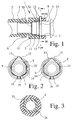
- Fig. 3
- einen Schnitt durch die in Fig. 1 dargestellte Steckkupplung längs der Linie III-III,
- Fig. 4
- einen Längsschnitt durch einen Teil einer Kupplungsaufnahme einer erfindungsgemäßen Steckkupplung,
- Fig. 5
- den Gegenstand nach Fig. 4 in Richtung der Pfeile V gesehen,
- Fig. 6
- einen Längsschnitt durch einen weiteren Teil einer Kupplungsaufnahme einer erfindungsgemäßen Steckkupplung, wobei der dargestellte Teil einer Kupplungsaufnahme den in Fig. 4 dargestellten Teil ergänzt,
- Fig. 7
- den Gegenstand nach Fig. 6 in Richtung des Pfeils VII gesehen,
- Fig. 8
- eine Draufsicht auf eine bevorzugte Ausführungsform einer zu der erfindungsgemäßen Steckkupplung gehörenden Verriegelungsfeder, im gestreckten Zustand,
- Fig. 9
- eine Seitenansicht der in Fig. 8 dargestellten Verriegelungsfeder, mit bereits funktionsgerecht abgebogenen Verriegelungsabschnitten, im unbelasteten Zustand,
- Fig. 10
- eine perspektivische Darstellung der Verriegelungsfeder nach Fig. 9, im Einbauzustand,
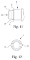
- Fig. 11
- eine Seitenansicht eines Teils eines zu der erfindungsgemäßen Steckkupplung gehörenden Kupplungssteckers und
- Fig. 12
- den Gegenstand nach Fig. 11 in Richtung des Pfeils XII gesehen.
Claims (14)
- Steckkupplung (1), insbesondere für Schlauchverbindungen und zur Verwendung in Kraftfahrzeugen, mit einer Kupplungsaufnahme (3) und mit einem Kupplungsstecker (4), wobei die Kupplungsaufnahme (3) mit einer Einstecköffnung (7) für den Kupplungsstecker (4) versehen ist und mindestens eine der Verriegelung von Kupplungsaufnahme (3) und Kupplungsstecker (4) dienende Verriegelungsfeder (8) aufweist und an der Verriegelungsfeder (8) mindestens ein Verriegelungsabschnitt (9, 10) und ein von der Außenseite der Kupplungsaufnahme (3) her betätigbarer Entriegelungsabschnitt (13) vorgesehen sind, dadurch gekennzeichnet, daß die Kupplungsaufnahme (3) eine zur Einstecköffnung (7) hin zumindest teilweise offene Nut (14) aufweist und die Verriegelungsfeder (8) unverlierbar in der Nut (14) vorgesehen ist.
- Steckkupplung nach Anspruch 1, dadurch gekennzeichnet, daß von der Verriegelungsfeder (8) nur der Entriegelungsabschnitt (13) von der Außenseite der Kupplungsaufnahme (3) her zugänglich ist.
- Steckkupplung nach Anspruch 1 oder 2, dadurch gekennzeichnet, daß die Kupplungsaufnahme (3) eine in die Nut (14) mündende, von der Außenseite - vorzugsweise über ein Verriegelungsteil - her zugängliche Entriegelungsöffnung (15) aufweist und sich die Verriegelungsfeder (8) mit ihrem Entriegelungsabschnitt (13) von der Nut (14) in die Entriegelungsöffnung (15) hinein erstreckt.
- Steckkupplung nach einem der Ansprüche 1 bis 3, dadurch gekennzeichnet, daß die Verriegelungsfeder (8) so ausgebildet und in der Nut (14) angeordnet ist, daß die Entriegelung durch Aufbringen einer Kraft (E) auf den Entriegelungsabschnitt (13) der Verriegelungsfeder (8) erfolgt und dadurch der Verriegelungsabschnitt (9, 10) etwa in radialer Richtung in die Nut (14) hinein bewegt wird und außer Eingriff mit dem Kupplungsstecker (4) kommt.
- Steckkupplung nach einem der Ansprüche 1 bis 4, dadurch gekennzeichnet, daß die Nut (14) als Umfangsnut ausgebildet ist und die Verriegelungsfeder (8) umlaufend in der Nut (14) angeordnet ist.
- Steckkupplung nach einem der Ansprüche 1 bis 5, dadurch gekennzeichnet, daß die Verriegelungsfeder (8) als zweischenkelige Blattfeder ausgebildet ist, an jedem Schenkel (16, 17) wenigstens ein in Richtung auf den anderen Schenkel (17, 16) abgewinkelter Verriegelungsabschnitt (9, 10) vorgesehen ist und der Schenkelgrund den Entriegelungsabschnitt (13) bildet.
- Steckkupplung nach Anspruch 6, dadurch gekennzeichnet, daß im nicht-eingebauten Zustand der Verriegelungsfeder (8) die Schenkel (16, 17) miteinander einen Winkel von 70° bis 110°, vorzugsweise von etwa 90° bilden.
- Steckkupplung nach einem der Ansprüche 1 bis 7, dadurch gekennzeichnet, daß die Verriegelungsfeder (8) in der Nut (14) an ihrem dem Entriegelungsabschnitt (13) gegenüberliegenden Bereich - mindestens an einer Stelle, vorzugsweise an zwei Stellen - gehalten ist.
- Steckkupplung nach Anspruch 8, dadurch gekennzeichnet, daß im nicht-eingebauten Zustand der Verriegelungsfeder (8) die Enden (18, 19) der Schenkel (16, 17) in einem Winkel von 40° bis 80° abgewinkelt und die abgewinkelten Enden (18, 19) der Schenkel (16, 17) in einen radialen Schlitz oder in radialen Sclitzen (20) in der Kupplungsaufnahme (3) eingesetzt sind.
- Steckkupplung nach Anspruch 8 oder 9, dadurch gekennzeichnet, daß im Bereich der Verriegelungsabschnitte (9, 10) der Verriegelungsfeder (8) die Nut (14) tiefer ist als im Bereich der Halterung der Verriegelungsfeder (8).
- Steckkupplung nach einem der Ansprüche 1 bis 10, dadurch gekennzeichnet, daß die Verriegelungsabschnitte (9, 10) der Verriegelungsfeder (8) auf gegenüberliegenden Seiten etwa im rechten Winkel zum Entriegelungsabschnitt (13) vorgesehen sind.
- Steckkupplung nach einem der Ansprüche 1 bis 11, dadurch gekennzeichnet, daß die Kupplungsaufnahme (3) einen Grundkörper (21) und ein Abschlußteil (22) aufweist.
- Steckkupplung nach Anspruch 12, dadurch gekennzeichnet, daß die Nut (14) teilweise in dem Grundkörper (21) teilweise in dem Abschlußteil (22) ausgebildet ist.
- Steckkupplung nach einem der Ansprüche 1 bis 13, dadurch gekennzeichnet, daß zwischen der Kupplungsaufnahme (3) und dem Kupplungsstecker (4) eine Verdrehsicherung vorgesehen ist.
Applications Claiming Priority (4)
| Application Number | Priority Date | Filing Date | Title |
|---|---|---|---|
| DE19839726 | 1998-05-26 | ||
| DE19839726 | 1998-05-26 | ||
| DE19827763 | 1998-06-24 | ||
| DE19827763 | 1998-06-24 |
Publications (2)
| Publication Number | Publication Date |
|---|---|
| EP0961071A2 true EP0961071A2 (de) | 1999-12-01 |
| EP0961071A3 EP0961071A3 (de) | 2001-03-21 |
Family
ID=26046968
Family Applications (1)
| Application Number | Title | Priority Date | Filing Date |
|---|---|---|---|
| EP99108327A Withdrawn EP0961071A3 (de) | 1998-05-26 | 1999-04-28 | Steckkupplung |
Country Status (5)
| Country | Link |
|---|---|
| US (1) | US6186180B1 (de) |
| EP (1) | EP0961071A3 (de) |
| BR (1) | BR9902380A (de) |
| DE (1) | DE19852395C2 (de) |
| MX (1) | MXPA99004776A (de) |
Cited By (2)
| Publication number | Priority date | Publication date | Assignee | Title |
|---|---|---|---|---|
| FR2812065A1 (fr) * | 2000-07-24 | 2002-01-25 | Caillau Ets | Embout de connexion rapide |
| FR2891889A1 (fr) | 2005-10-07 | 2007-04-13 | Caillau Ets | Embout de connexion etanche et piece terminale pour un tel embout |
Families Citing this family (11)
| Publication number | Priority date | Publication date | Assignee | Title |
|---|---|---|---|---|
| SE0004701D0 (sv) * | 2000-12-19 | 2000-12-19 | Siemens Elema Ab | Narkosmedelförgasare |
| US7389798B2 (en) * | 2004-04-08 | 2008-06-24 | Smc Corporation Of America | Plug for a port |
| DE102005033665A1 (de) | 2005-07-19 | 2007-02-08 | Elsässer, Helmut | Aufnahmeteil für einen Stecker |
| US7568567B2 (en) * | 2006-08-02 | 2009-08-04 | Gm Global Technology Operations, Inc. | Snap-ring with additional loop |
| DE102007031614A1 (de) * | 2007-07-06 | 2009-01-08 | Daimler Ag | Ladeluftschlauch |
| US20100025079A1 (en) * | 2008-07-31 | 2010-02-04 | Flynn William T | Electrical bonding device for telescoping fluid line assembly |
| EP2597348A1 (de) * | 2011-11-24 | 2013-05-29 | Eaton Germany GmbH | Steckanschluss für eine Halteklammer |
| US8979559B2 (en) | 2011-12-14 | 2015-03-17 | Cooper Technologies Company | Lockout tagout plug sleeve |
| DE102017125915B4 (de) * | 2017-11-07 | 2026-01-29 | Phoenix Contact Gmbh & Co. Kg | Verriegelung für Steckverbinder |
| DE102019001812A1 (de) * | 2019-03-15 | 2020-09-17 | Volkswagen Aktiengesellschaft | Rohr-Schlauch-Anordnung |
| CN110594508A (zh) * | 2019-09-10 | 2019-12-20 | 宁波海连汽配科技有限公司 | 一种可拆卸的单扣式连接器 |
Family Cites Families (10)
| Publication number | Priority date | Publication date | Assignee | Title |
|---|---|---|---|---|
| DE387688C (de) * | 1921-03-06 | 1924-01-02 | Robert Bosch Akt Ges | Leicht loesbare Verbindung von Apparatteilen |
| US2023428A (en) * | 1934-07-06 | 1935-12-10 | Frederick C Liebhardt | Coupling |
| US3574362A (en) * | 1969-04-17 | 1971-04-13 | Stewart Warner Corp | Vacuum system coupling |
| US3584902A (en) * | 1969-07-09 | 1971-06-15 | Anchor Coupling Co Inc | Quick-connect safety coupling |
| US3922011A (en) * | 1973-12-11 | 1975-11-25 | Tom Walters | Hose coupling |
| US4884829A (en) * | 1986-09-16 | 1989-12-05 | Johannes Schaefer Vorm. Stettiner Schraubenwerke Gmbh & Co. Kg | Plug-in connection for connecting tube and host lines in particular for use in tube-line systems of motor vehicles |
| DE4318878A1 (de) * | 1993-06-08 | 1994-12-15 | Kuehner Gmbh & Cie | Kältemittelkupplung zur Verbindung von Kältemittelleitungen |
| FR2710717B1 (fr) * | 1993-10-01 | 1995-12-22 | Caillau Ets | Connexion rapide pour emmanchement d'un tube rigide dans un embout. |
| WO1997028396A1 (en) * | 1996-01-29 | 1997-08-07 | Sloane Norman S | Splined safety lock with resilient retaining ring |
| GB9620011D0 (en) * | 1996-09-25 | 1996-11-13 | Bend All Mfg Inc | Snap-in end fitting for pipes |
-
1998
- 1998-11-13 DE DE19852395A patent/DE19852395C2/de not_active Expired - Fee Related
-
1999
- 1999-04-28 EP EP99108327A patent/EP0961071A3/de not_active Withdrawn
- 1999-05-20 US US09/315,158 patent/US6186180B1/en not_active Expired - Fee Related
- 1999-05-24 MX MXPA99004776A patent/MXPA99004776A/es not_active IP Right Cessation
- 1999-05-26 BR BR9902380-6A patent/BR9902380A/pt not_active Application Discontinuation
Cited By (3)
| Publication number | Priority date | Publication date | Assignee | Title |
|---|---|---|---|---|
| FR2812065A1 (fr) * | 2000-07-24 | 2002-01-25 | Caillau Ets | Embout de connexion rapide |
| WO2002008655A1 (fr) * | 2000-07-24 | 2002-01-31 | Etablissements Caillau | Embout de connexion rapide |
| FR2891889A1 (fr) | 2005-10-07 | 2007-04-13 | Caillau Ets | Embout de connexion etanche et piece terminale pour un tel embout |
Also Published As
| Publication number | Publication date |
|---|---|
| DE19852395A1 (de) | 1999-12-09 |
| US6186180B1 (en) | 2001-02-13 |
| MXPA99004776A (es) | 2005-09-06 |
| DE19852395C2 (de) | 2003-02-27 |
| BR9902380A (pt) | 2000-01-18 |
| EP0961071A3 (de) | 2001-03-21 |
Similar Documents
| Publication | Publication Date | Title |
|---|---|---|
| EP2439439B1 (de) | Verbindungselement für eine Fluidverbindung | |
| DE19946260C1 (de) | Schnellkupplung für Schläuche oder Rohrleitungen in Kraftfahrzeugen | |
| EP3149384B1 (de) | Steckverbinder für fluidleitungen mit innenliegender adapterhülse | |
| EP1841016B1 (de) | Metallischer Steckverbinder | |
| DE10024303B4 (de) | Aufnahme-Kupplungsvorrichtung einer Steckkupplung und Steckkupplung mit der Aufnahme-Kupplungsvorrichtung | |
| EP1969279B1 (de) | Kupplungsteil für steckverbinderanordnung | |
| DE102010010522B4 (de) | Steckverbinder für Medienleitungen | |
| DE8915932U1 (de) | Rohrverbinder | |
| EP0961071A2 (de) | Steckkupplung | |
| DE102020108073A1 (de) | Steckverbinder mit Vormontagesicherung | |
| EP2615347A2 (de) | Kupplungselement und Entriegelungselement für das Kupplungselement | |
| DE4214105A1 (de) | Steckverbinder fuer schlauch- oder rohrleitungen, insbesondere fuer kraftstoffleitungen von verbrennungsmotoren | |
| EP1724510B1 (de) | Steckkupplung | |
| EP1969280B1 (de) | Steckteil für steckverbinderanordnung | |
| EP0984524B1 (de) | Zweiteiliger elektrischer Steckverbinder mit einem Koppelteil und einem bewegbaren Kontrollelement | |
| DE9105436U1 (de) | Steckverbinderanordnung | |
| EP2405173A2 (de) | Schnellkupplung für Fluidleitungen | |
| EP1733164B1 (de) | Steckverbindung mit winkelarretierung | |
| EP3679633B1 (de) | Einzugshilfe von elektrischen steckverbindern mit verschieberichtung in steckrichtung | |
| DE202011107042U1 (de) | Verbindungseinheit, Verbindungsanordnung mit einer derartigen Verbindungseinheit und Verbindungsbausatz mit einer derartigen Verbindungseinheit oder einer derartigen Verbindungsanordnung | |
| DE202012102801U1 (de) | Steckverbindung zum gesicherten Verbinden von Leitungssystemen | |
| DE4217646C1 (en) | Push in connector for two pipe sections - has coaxially interfitting connectors with spring clip locked even in release position on one part by locking element with detent allowing pre-fitting | |
| WO2009100964A1 (de) | Steckverbindung für heizleiter an rohrleitungen | |
| EP3288121A1 (de) | Komplett abgedichteter steckverbinder mit verbesserten haltekräften | |
| EP0641945B1 (de) | Betätigungszug für die Betätigung von Einrichtungen insbesondere in Fahrzeugen |
Legal Events
| Date | Code | Title | Description |
|---|---|---|---|
| PUAI | Public reference made under article 153(3) epc to a published international application that has entered the european phase |
Free format text: ORIGINAL CODE: 0009012 |
|
| AK | Designated contracting states |
Kind code of ref document: A2 Designated state(s): DE ES FR GB IT SE |
|
| AX | Request for extension of the european patent |
Free format text: AL;LT;LV;MK;RO;SI |
|
| PUAL | Search report despatched |
Free format text: ORIGINAL CODE: 0009013 |
|
| RIC1 | Information provided on ipc code assigned before grant |
Free format text: 7F 16L 37/14 A, 7F 16L 37/088 B, 7F 16L 37/084 B |
|
| AK | Designated contracting states |
Kind code of ref document: A3 Designated state(s): AT BE CH CY DE DK ES FI FR GB GR IE IT LI LU MC NL PT SE |
|
| AX | Request for extension of the european patent |
Free format text: AL;LT;LV;MK;RO;SI |
|
| 17P | Request for examination filed |
Effective date: 20010821 |
|
| AKX | Designation fees paid |
Free format text: DE ES FR GB IT SE |
|
| 17Q | First examination report despatched |
Effective date: 20050513 |
|
| GRAP | Despatch of communication of intention to grant a patent |
Free format text: ORIGINAL CODE: EPIDOSNIGR1 |
|
| STAA | Information on the status of an ep patent application or granted ep patent |
Free format text: STATUS: THE APPLICATION IS DEEMED TO BE WITHDRAWN |
|
| 18D | Application deemed to be withdrawn |
Effective date: 20070321 |