EP0960563A2 - Animal cage - Google Patents
Animal cage Download PDFInfo
- Publication number
- EP0960563A2 EP0960563A2 EP99110127A EP99110127A EP0960563A2 EP 0960563 A2 EP0960563 A2 EP 0960563A2 EP 99110127 A EP99110127 A EP 99110127A EP 99110127 A EP99110127 A EP 99110127A EP 0960563 A2 EP0960563 A2 EP 0960563A2
- Authority
- EP
- European Patent Office
- Prior art keywords
- sides
- cage
- animal cage
- cage according
- hinges
- Prior art date
- Legal status (The legal status is an assumption and is not a legal conclusion. Google has not performed a legal analysis and makes no representation as to the accuracy of the status listed.)
- Withdrawn
Links
- 238000005452 bending Methods 0.000 claims description 5
- 238000004806 packaging method and process Methods 0.000 description 3
- 230000008878 coupling Effects 0.000 description 2
- 238000010168 coupling process Methods 0.000 description 2
- 238000005859 coupling reaction Methods 0.000 description 2
- 230000007423 decrease Effects 0.000 description 2
- 238000005273 aeration Methods 0.000 description 1
- 238000010276 construction Methods 0.000 description 1
- 238000003466 welding Methods 0.000 description 1
Images


Classifications
-
- A—HUMAN NECESSITIES
- A01—AGRICULTURE; FORESTRY; ANIMAL HUSBANDRY; HUNTING; TRAPPING; FISHING
- A01K—ANIMAL HUSBANDRY; CARE OF BIRDS, FISHES, INSECTS; FISHING; REARING OR BREEDING ANIMALS, NOT OTHERWISE PROVIDED FOR; NEW BREEDS OF ANIMALS
- A01K31/00—Housing birds
- A01K31/06—Cages, e.g. for singing birds
- A01K31/08—Collapsible cages
Definitions
- the invention concerns an animal cage for industrial or domestic use, characterized in that it can be folded.
- the known cages can have any shape and in most cases have polyhedral base and comprise a bottom, a top and one or more sides.
- the volume defined by the sides, the bottom and the top constitute the space within which the animal can move.
- the storage cost decreases as the number of cages that can be stored in a given volume increases. In other words, the storage cost decreases if the number of cages per unit of volume can be increased.
- a further cost that affects the price of the cage is constituted by the transport cost, which also depends on the volume occupied by each cage and consequently on the number of cages that can be transported by the same means.
- the cages are obtained by welding all their components, that is, the top, the bottom and the sides.
- these cages are supplied with all their components, that is, top, bottom and sides, separated and not assembled by the manufacturer.
- the assembly must be carried out by the dealer or by the final user.
- a considerable reduction in the storage and transport costs can be obtained, but there is the inconvenience that the customer or dealer must provide for assembling the cage. This means that in this application the costs have been cut to the detriment of the practicality of the item.
- the aim of the present invention is the implementation of a cage whose overall dimensions can be reduced as much as possible for storage and transport, even if it is supplied with most of its essential components already assembled.
- a further aim to be achieved is the implementation of a cage for the final assembly of which only easy and quick operations are required.
- an animal cage that, according to the main claim, comprises at least a bottom and a top to be coupled to relevant sides, and is characterized in that each one of said sides is connected to the adjacent sides through articulation means suitable for ensuring a reciprocal rotation of at least 90°.
- the articulation means are constituted by hinges obtained by bending at least a portion of the perimetrical edge of each side.
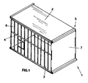
- Figure 1 which is a perspective view of the cage subject of the invention when assembled and in which the cage is indicated as a whole by 1, the cage has the shape of a polyhedron with rectangular base.
- It comprises a top 2 and a bottom 3 that are removably connected to four sides, a front side 4, a rear side 5 and two lateral sides 6 and 7, positioned vertically and connected to one another in correspondence with their adjacent sides.
- Each side is connected to the adjacent side through articulation means that, in the specific case described herein, are constituted by hinges suitable for ensuring the reciprocal rotation of the sides of at least 90°.
- Figures 6 and 7 are magnified views of the two hinges 100 and 101 that connect the lateral side 7 to the front side 4 and the lateral side 6 to the rear side 5, respectively.
- the hinge 100 is obtained by bending the terminal edge 71 of the blind side 7 in such a way as to hook the vertical wire 41 constituting the terminal corner of the side 4.
- the hinge 101 instead, is obtained by bending the terminal edges 61 and 51 of both sides 6 and 5, so that said edges are staggered with respect to each other.
- a pin 26 inserted in the hinge 101 connects the two sides 5 and 6 to each other.
- the sides define a deformable structure and can be positioned one over the other for packaging and transport purposes. Upon assembly they can be spaced from one another in such a way as to define the practically rectangular configuration that makes up the cage.
- the two lateral sides 6 and 7 are provided with coupling means suitable for removably housing the top 2 and the bottom 3 and preferably positioned near their lower and upper edges.
- said coupling means comprise upper guides 8, 9 and lower guides 10, 11, obtained by bending the sides 6 and 7 near their upper and lower edges.
- the upper guides 8 and 9 house the corresponding side edges of the top 2, indicated by 12 and 13.
- the lower guides 10 and 11 house the corresponding side edges 14 and 15 of the bottom 3.
- the fitting of the top 2 is achieved by inserting one end of the edges 12 and 13 in the guides 8 and 9 and by pushing the top in the direction 16 until it touches the rear side 5.
- the fitting of the bottom 3 is achieved by inserting one end of the edges 14 and 15 in the guides 10 and 11 and by pushing the bottom 3 in the direction 17 until it touches the rear side 5.
- top and bottom in their housings ensures the necessary stiffness of the whole cage.
- the cage can be folded for packaging purposes, as represented in Figures 3 and 4, by horizontally moving two opposite vertical sides along parallel, but opposite directions.
- Figure 4 shows the reduction in volume obtained owing to the articulation means provided on the cage.
- the movement of the sides is possible thanks to the presence of the hinges and so when the structure is in the most compact position the sides practically lie on the same plane.
- the sides, top and bottom of the cage can be manufactured in different shapes and materials.
- the front side 4 is made of a wire net, while the other sides, the top and the bottom are made of plate.
- the front side 18 of the cage has the upper part indicated by 18a bent in the shape of an L, so that it constitutes a part of the cage top.
- the side 18 is provided with a terminal element 19 that can be raised and lowered.
- Said terminal element is connected to the front side through articulation means and is provided with a guide 20 suitable for housing the front part of the bottom 21.
- the dimensions of the top 23 are such as to cover the space defined by the lateral sides 35 and 36, by the rear side 22 and by the bent part 18a of the front side 18.
- Two guides 24 and 25 suitable for housing the top 23 and the bottom 21, respectively, are also provided near the lower and upper edges of the rear side 22.
- the articulation means used to connect the cage sides are constituted by hinges and can be of different types.
- Figure 8 shows a possible connection of two wire net sides 30 and 40 in a cage that is not represented. In this case some horizontal wires 31 of the side 30 are hooked to the last vertical wire 42 that belongs to the adjacent side 40 and serves as a pin.
- the articulation means employed in the invention may also be hinges that can be uncoupled, in such a way as to permit the reciprocal disconnection of two adjacent sides.
- the packaging of the cage can be further optimized.
- the cage base can have any shape and that any material can be used for the construction of the cage.
Abstract
Description
- The invention concerns an animal cage for industrial or domestic use, characterized in that it can be folded.
- The known cages can have any shape and in most cases have polyhedral base and comprise a bottom, a top and one or more sides. The volume defined by the sides, the bottom and the top constitute the space within which the animal can move.
- One of the components that significantly affect the price of the cage is the storage cost. This cost decreases as the number of cages that can be stored in a given volume increases. In other words, the storage cost decreases if the number of cages per unit of volume can be increased.
- A further cost that affects the price of the cage is constituted by the transport cost, which also depends on the volume occupied by each cage and consequently on the number of cages that can be transported by the same means.
- According to a known application, the cages are obtained by welding all their components, that is, the top, the bottom and the sides.
- According to what has been stated above, the drawback of this kind of cages is clearly represented by the fact that they occupy considerable volumes and therefore have high storage and transport costs, which consequently affects the final price of the cage itself.
- According to another known application, these cages are supplied with all their components, that is, top, bottom and sides, separated and not assembled by the manufacturer. The assembly must be carried out by the dealer or by the final user. In this case a considerable reduction in the storage and transport costs can be obtained, but there is the inconvenience that the customer or dealer must provide for assembling the cage. This means that in this application the costs have been cut to the detriment of the practicality of the item.
- The aim of the present invention is the implementation of a cage whose overall dimensions can be reduced as much as possible for storage and transport, even if it is supplied with most of its essential components already assembled.
- A further aim to be achieved is the implementation of a cage for the final assembly of which only easy and quick operations are required.
- These final operations that must be carried out by the shopkeeper or by the final user must be extremely easy, so that they can be performed even by unskilled persons.
- The aims mentioned above and others that will be described in greater detail below have been achieved through the implementation of an animal cage that, according to the main claim, comprises at least a bottom and a top to be coupled to relevant sides, and is characterized in that each one of said sides is connected to the adjacent sides through articulation means suitable for ensuring a reciprocal rotation of at least 90°.
- According to a favourite application of the invention, the articulation means are constituted by hinges obtained by bending at least a portion of the perimetrical edge of each side.
- Further characteristics of the invention will be highlighted in greater detail in the description of some among many possible applications of the invention in question, illustrated in the attached drawings, wherein:
- Fig. 1 is a perspective view of the cage subject of the invention when assembled;
- Fig. 2 is an exploded perspective view of the cage of Figure 1;
- Fig. 3 is a front view of the cage when folded in such a way as to occupy the minimum possible volume;
- Fig. 4 is a top view of the cage of Figure 3;
- Fig. 5 is an exploded perspective view of another application of the cage subject of the invention;
- Fig. 6 is a magnified view of a particular implementation of the articulation means;
- Fig. 7 is a magnified view of a second, different implementation of the articulation means;
- Fig. 8 is a magnified view of a further implementation of the articulation means.
- In Figure 1, which is a perspective view of the cage subject of the invention when assembled and in which the cage is indicated as a whole by 1, the cage has the shape of a polyhedron with rectangular base.
- It comprises a
top 2 and abottom 3 that are removably connected to four sides, afront side 4, arear side 5 and twolateral sides - Each side is connected to the adjacent side through articulation means that, in the specific case described herein, are constituted by hinges suitable for ensuring the reciprocal rotation of the sides of at least 90°.
- Figures 6 and 7 are magnified views of the two
hinges lateral side 7 to thefront side 4 and thelateral side 6 to therear side 5, respectively. - The
hinge 100 is obtained by bending the terminal edge 71 of theblind side 7 in such a way as to hook thevertical wire 41 constituting the terminal corner of theside 4. - The
hinge 101, instead, is obtained by bending theterminal edges sides pin 26 inserted in thehinge 101 connects the twosides - In this way the sides define a deformable structure and can be positioned one over the other for packaging and transport purposes. Upon assembly they can be spaced from one another in such a way as to define the practically rectangular configuration that makes up the cage.
- The two
lateral sides top 2 and thebottom 3 and preferably positioned near their lower and upper edges. In the application represented in Figures 1 and 2, said coupling means compriseupper guides 8, 9 andlower guides sides upper guides 8 and 9 house the corresponding side edges of thetop 2, indicated by 12 and 13. Thelower guides corresponding side edges bottom 3. The fitting of thetop 2 is achieved by inserting one end of theedges guides 8 and 9 and by pushing the top in thedirection 16 until it touches therear side 5. The fitting of thebottom 3 is achieved by inserting one end of theedges guides bottom 3 in thedirection 17 until it touches therear side 5. - The fitting of top and bottom in their housings ensures the necessary stiffness of the whole cage. In fact, the parallelism and squareness of the cage sides due to the presence of top and bottom, together with the constraints provided by the articulation means, ensure the necessary rigidity.
- Obviously, if the
top 2 and thebottom 3 are removed, the structure constituted by the sides becomes unstable. - The cage can be folded for packaging purposes, as represented in Figures 3 and 4, by horizontally moving two opposite vertical sides along parallel, but opposite directions.
- Figure 4 shows the reduction in volume obtained owing to the articulation means provided on the cage. The movement of the sides is possible thanks to the presence of the hinges and so when the structure is in the most compact position the sides practically lie on the same plane.
- The assembly and disassembly of the cage are quite easy and no special tools or skills are required.
- The sides, top and bottom of the cage can be manufactured in different shapes and materials.
- In the case represented in Figure 1, the
front side 4 is made of a wire net, while the other sides, the top and the bottom are made of plate. - According to a further application of the invention shown in Figure 5, the
front side 18 of the cage has the upper part indicated by 18a bent in the shape of an L, so that it constitutes a part of the cage top. In its lower part theside 18 is provided with aterminal element 19 that can be raised and lowered. Said terminal element is connected to the front side through articulation means and is provided with aguide 20 suitable for housing the front part of thebottom 21. - The dimensions of the
top 23 are such as to cover the space defined by thelateral sides rear side 22 and by thebent part 18a of thefront side 18. - Two
guides top 23 and thebottom 21, respectively, are also provided near the lower and upper edges of therear side 22. - In this way, thanks to the special L-shaped structure of the
front side 18, better aeration of the cage inside and more visibility through the top have been achieved. - Furthermore, the presence of the guides either on the
rear side 24 and on theterminal element 19 of the front side increases the stiffness of the cage. - The articulation means used to connect the cage sides are constituted by hinges and can be of different types.
- Figure 8 shows a possible connection of two wire
net sides horizontal wires 31 of theside 30 are hooked to the last vertical wire 42 that belongs to theadjacent side 40 and serves as a pin. - The articulation means employed in the invention may also be hinges that can be uncoupled, in such a way as to permit the reciprocal disconnection of two adjacent sides.
- In this case the packaging of the cage can be further optimized.
- It is obvious that the cage base can have any shape and that any material can be used for the construction of the cage.
Claims (7)
- Animal cage with polyhedral base, comprising at least one bottom and one top that can be coupled to the respective sides, characterized in that each one of said sides is connected to the sides adjacent to it through articulation means suitable for ensuring a reciprocal rotation of at least 90°.
- Animal cage according to claim 1, characterized in that the articulation means of the sides are hinges (100, 101).
- Animal cage according to claim 1, characterized in that the hinges (100, 101) can be uncoupled.
- Animal cage according to claim 2, characterized in that said hinges are obtained by bending at least a lateral portion (51, 61, 71) of said sides (5, 6, 7).
- Animal cage according to claim 2, characterized in that the connection element between the two sides is constituted by the last vertical wire (42) of a side made of wire net.
- Animal cage according to claim 1, characterized in that the bottom (3, 21) is slidably movable through parallel guides (11) belonging to the lateral sides (6, 7).
- Animal cage according to one of the previous claims, characterized in that the top (2, 23) is slidably movable through parallel guides belonging to the lateral sides (6, 7).
Applications Claiming Priority (2)
| Application Number | Priority Date | Filing Date | Title |
|---|---|---|---|
| ITVI980043 | 1998-05-27 | ||
| IT98VI000043 IT245442Y1 (en) | 1998-05-27 | 1998-05-27 | ANIMAL CAGE |
Publications (2)
| Publication Number | Publication Date |
|---|---|
| EP0960563A2 true EP0960563A2 (en) | 1999-12-01 |
| EP0960563A3 EP0960563A3 (en) | 2000-05-31 |
Family
ID=11426613
Family Applications (1)
| Application Number | Title | Priority Date | Filing Date |
|---|---|---|---|
| EP99110127A Withdrawn EP0960563A3 (en) | 1998-05-27 | 1999-05-25 | Animal cage |
Country Status (2)
| Country | Link |
|---|---|
| EP (1) | EP0960563A3 (en) |
| IT (1) | IT245442Y1 (en) |
Cited By (2)
| Publication number | Priority date | Publication date | Assignee | Title |
|---|---|---|---|---|
| GB2374510A (en) * | 2001-04-17 | 2002-10-23 | Neil Botterill | Folding vivarium |
| WO2005077158A1 (en) * | 2004-02-12 | 2005-08-25 | Cabrera Garcia Francisco Javie | Cage comprising a disposable structure |
Family Cites Families (4)
| Publication number | Priority date | Publication date | Assignee | Title |
|---|---|---|---|---|
| US2789531A (en) * | 1955-04-11 | 1957-04-23 | Aurel E Diefendorf | Collapsible cage for birds |
| US2864335A (en) * | 1956-11-15 | 1958-12-16 | Yellin Bernard | Collapsible bird cage |
| US5016570A (en) * | 1990-05-04 | 1991-05-21 | Henson J Peter | Collapsible carrying container for animals |
| DE9414629U1 (en) * | 1994-09-09 | 1994-11-17 | Reif Waltraud | Modular container made of grid parts to be placed on the floor |
-
1998
- 1998-05-27 IT IT98VI000043 patent/IT245442Y1/en active
-
1999
- 1999-05-25 EP EP99110127A patent/EP0960563A3/en not_active Withdrawn
Non-Patent Citations (1)
| Title |
|---|
| None |
Cited By (3)
| Publication number | Priority date | Publication date | Assignee | Title |
|---|---|---|---|---|
| GB2374510A (en) * | 2001-04-17 | 2002-10-23 | Neil Botterill | Folding vivarium |
| GB2374510B (en) * | 2001-04-17 | 2005-11-02 | Neil Botterill | Folding vivarium |
| WO2005077158A1 (en) * | 2004-02-12 | 2005-08-25 | Cabrera Garcia Francisco Javie | Cage comprising a disposable structure |
Also Published As
| Publication number | Publication date |
|---|---|
| IT245442Y1 (en) | 2002-03-20 |
| ITVI980043U1 (en) | 1998-08-25 |
| EP0960563A3 (en) | 2000-05-31 |
Similar Documents
| Publication | Publication Date | Title |
|---|---|---|
| US4211331A (en) | Merchandising display | |
| US7059274B2 (en) | Combinative pet cage | |
| US5315936A (en) | Erectable display stand | |
| KR100947238B1 (en) | Assemble-in-place modular storage | |
| AU609136B2 (en) | A portable display panel and hinge system | |
| US9713379B1 (en) | Shelf supporting beam configuration for shelving apparatus | |
| US20080083682A1 (en) | Display stand merchandise tray | |
| US7248464B1 (en) | Structure of a computer housing | |
| CN205793829U (en) | Structure of battery corer and electronic scale | |
| EP0960563A2 (en) | Animal cage | |
| US5934584A (en) | Base frame for paper comminuting devices | |
| US5206757A (en) | Collapsible field glasses | |
| GB2327733A (en) | Linking module for stackable containers | |
| CN218568359U (en) | High-definition projection display device | |
| US20060273083A1 (en) | Modular bin system and bin | |
| EP0849984A1 (en) | A modular cabinet | |
| WO1998055982A1 (en) | Display case for two- and three-dimensional objects | |
| EP0285193A1 (en) | System for assembling an item of furniture | |
| CN209834669U (en) | Access device for logistics objects | |
| JP3225822U (en) | Assembling type case | |
| CA2559432A1 (en) | Display stand merchandise tray | |
| KR200378931Y1 (en) | Paper Frame | |
| CN212630295U (en) | Pin-connected panel cabinet body and express delivery cabinet | |
| CN214709497U (en) | Assemble pet house | |
| CN219936615U (en) | Thin double-sided display electronic equipment |
Legal Events
| Date | Code | Title | Description |
|---|---|---|---|
| PUAI | Public reference made under article 153(3) epc to a published international application that has entered the european phase |
Free format text: ORIGINAL CODE: 0009012 |
|
| AK | Designated contracting states |
Kind code of ref document: A2 Designated state(s): AT BE CH CY DE DK ES FI FR GB GR IE IT LI LU MC NL PT SE |
|
| AX | Request for extension of the european patent |
Free format text: AL;LT;LV;MK;RO;SI |
|
| PUAL | Search report despatched |
Free format text: ORIGINAL CODE: 0009013 |
|
| AK | Designated contracting states |
Kind code of ref document: A3 Designated state(s): AT BE CH CY DE DK ES FI FR GB GR IE IT LI LU MC NL PT SE |
|
| AX | Request for extension of the european patent |
Free format text: AL;LT;LV;MK;RO;SI |
|
| RAP1 | Party data changed (applicant data changed or rights of an application transferred) |
Owner name: ITALGABBIE S.R.L. |
|
| STAA | Information on the status of an ep patent application or granted ep patent |
Free format text: STATUS: THE APPLICATION HAS BEEN WITHDRAWN |
|
| 18W | Application withdrawn |
Withdrawal date: 20001206 |