EP0959576A2 - Light source and method for transmitting spectrally encoded data - Google Patents
Light source and method for transmitting spectrally encoded data Download PDFInfo
- Publication number
- EP0959576A2 EP0959576A2 EP99440103A EP99440103A EP0959576A2 EP 0959576 A2 EP0959576 A2 EP 0959576A2 EP 99440103 A EP99440103 A EP 99440103A EP 99440103 A EP99440103 A EP 99440103A EP 0959576 A2 EP0959576 A2 EP 0959576A2
- Authority
- EP
- European Patent Office
- Prior art keywords
- light source
- frequency
- laser
- source according
- bit
- Prior art date
- Legal status (The legal status is an assumption and is not a legal conclusion. Google has not performed a legal analysis and makes no representation as to the accuracy of the status listed.)
- Withdrawn
Links
- 238000000034 method Methods 0.000 title claims description 13
- 239000004065 semiconductor Substances 0.000 claims abstract description 10
- 230000005540 biological transmission Effects 0.000 claims description 18
- 230000003595 spectral effect Effects 0.000 claims description 17
- 238000002347 injection Methods 0.000 claims description 8
- 239000007924 injection Substances 0.000 claims description 8
- 238000001228 spectrum Methods 0.000 abstract description 5
- 230000003287 optical effect Effects 0.000 description 18
- 230000008033 biological extinction Effects 0.000 description 1
- 230000015572 biosynthetic process Effects 0.000 description 1
- 210000001520 comb Anatomy 0.000 description 1
- 238000000295 emission spectrum Methods 0.000 description 1
- 230000000737 periodic effect Effects 0.000 description 1
- 230000010363 phase shift Effects 0.000 description 1
- 238000005496 tempering Methods 0.000 description 1
- 238000010626 work up procedure Methods 0.000 description 1
Images
Classifications
-
- H—ELECTRICITY
- H04—ELECTRIC COMMUNICATION TECHNIQUE
- H04J—MULTIPLEX COMMUNICATION
- H04J14/00—Optical multiplex systems
- H04J14/005—Optical Code Multiplex
Definitions
- the invention relates to a light source and a method for the Transmission of digital spectrally coded data according to the genus of Main claim.
- Such an optical transmission network consists of optical transmission lines and optical splitters as well possibly optical amplifiers and is used to transmit coded, multiplexed optical signals.
- Each transmitter contains an encoder, in which the signals to be transmitted into the optical before they are emitted Transmission network are coded.
- the coding is optical Ways, e.g. by frequency coding with an optical filter.
- everyone Receiver who wants to receive the data of a special transmitter must contain a decoder which determines the encoder of this Transmitter is tuned.
- the frequency ranges are transparent for optical signals, and the frequency ranges for optical Signals are blocked, the same for the encoder and for the decoder.
- This Coding is known as CDMA (Code Division Multiple Access) known.
- CDMA Code Division Multiple Access
- the Optical filter is, for example, a Fabry-Perot filter, which is the broadband Converts spectrum into a frequency comb.
- a major disadvantage of these known systems is the low optical output power for Available broadband light sources.
- the previously used Light-emitting diodes emit around 1,550 nm and that with very little anyway Power ( ⁇ 0.1 milliwatts), which in connection with passive optical filters leads to transmission powers in the range of approx. 30 ⁇ W. Therefore, in such Transmission systems always require an optical amplifier.
- the light source according to the invention with the characteristic features the independent claims has the advantage that much higher outputs can be achieved, and so on the use of an optical amplifier can be dispensed with.
- the broadband frequency comb for the Use of the CDMA procedure is necessary, actively manufactured.
- a DFB Distributed Feedback Laser
- Fabry-Perot laser is also a light source for the CDMA process possible.
- the formation of the spectral comb can in each case different bit periods can be selected differently.
- the spectral Coding of the signals is done by a receiver who has appropriate filter devices read.
- the basic advantage of the present invention is that a light source is provided that is actively an optical comb generated with frequency-periodic spectrum and as many equidistant as possible Contains lines with large integral laser power.
- the laser power is there integral over 1 mW.
- the spectral coding via the modulation of the Injection current is very flexible to the transmission ratios and to the Customizable number and performance of the receiving side.
- a Bit period means one at a bit rate of 10 megabits per second Duration of 100 ns.
- the semiconductor laser must be within this time be frequency or phase modulated. This is the injection current the semiconductor laser an additional low, high frequency Modulation current added.
- the modulation current can be, for example, with modulate the injection current at a frequency of 100 MHz.
- the Modulation of the injection current of the semiconductor laser occurs in the Output spectrum of the laser a frequency respectively phase-modulated output spectrum, the spectral width of which by a Modulation index m is given.
- This modulation index corresponds to m about the number of lines. It depends on the quotient from the frequency swing or phase shift and modulation frequency.
- the frequency swing is proportional to the amplitude of the high-frequency modulation current, the modulates the injection current with the modulation frequency.
- the Frequency shift be 10 GHz.
- an additional modulation current of a few mA is required.
- the distances between the Longitudinal modes of laser emission are set so that they correspond to integer multiples of the modulation frequency. Such Adjustment is made by tempering the Fabry-Perot laser.
- spectral coding in a transmission system a modulated laser light source is done by assigning the distance the periodic spectral components. It stands for every recipient a special frequency comb is available, the distance of which is specific to the corresponding recipient. The coding is done via the Modulation frequency, which is set accordingly. The Modulation frequency determines the distance between the lines. In order to can differ bit by bit with this transmission method Frequency combs are generated, the line spacing is typical.
- the Transmission method that with a particularly simple and low-cost transmitter can work up to bit rates of approx. 10 MHz.
- Each receiver has an optical filter. Only signals with the code specified for this receiver are optically transmitted and can be detected. It is generally detected in a filter curve with sin 2 curve to the maximum of the central spectral line. It is therefore possible to transmit a "1" or a "0" in a simple way: With a 1, the transmitter emits a spectral comb, and the receiver detects the central line. At zero, the operating point is shifted so that the emission of the spectral comb is shifted by half a line spacing. The receiver now detects a "0" in the central position.
- an active laser light source as a light source for a CDMA Transmission methods can still be optimized.
- Deliver without interference the laser light source according to the invention very narrow lines.
- the Use of very narrow lines can result in transmission special overlapping cases for a complete extinction of the Lead information.
- the bit error rate becomes lower when the spectral Lines are widened somewhat.
- the High-frequency signal superimposed on a phase noise.
- As the simplest case serves a noise oscillator 5, which with the high frequency generation in Connection is established.
- the transmission method also works using conventional light sources with external modulators.
- the light pipe is not so big in this case, but the transfer options correspond to the form outlined above.
Landscapes
- Engineering & Computer Science (AREA)
- Computer Networks & Wireless Communication (AREA)
- Signal Processing (AREA)
- Optical Communication System (AREA)
- Semiconductor Lasers (AREA)
Abstract
Es wird eine Lichtquelle mit einem breitbandigen frequenzperiodischen Ausgangsspektrum für digital spektralkodierte Daten vorgeschlagen, wobei die Lichtquelle aus einem Halbleiterlaser besteht, der innerhalb einer Bitperiode frequenz- oder phasenmoduliert wird. <IMAGE>A light source with a broadband frequency-periodic output spectrum for digital spectrally coded data is proposed, the light source consisting of a semiconductor laser which is frequency or phase modulated within a bit period. <IMAGE>
Description
Die Erfindung geht aus von einer Lichtquelle sowie einem Verfahren für die Übertragung von digitalen spektralkodierten Daten nach der Gattung des Hauptanspruches.The invention relates to a light source and a method for the Transmission of digital spectrally coded data according to the genus of Main claim.
Aus dem Stand der Technik ,beispielsweise aus der Patentanmeldung 197 231 03.9, sind Übertragungsverfahren unter Verwendung der spektralen Kodierung bekannt. Ein solches optisches Übertragungsnetz besteht aus optischen Übertragungsleitungen und optischen Splittern sowie gegebenenfalls optischen Verstärkern und dient zur Übertragung kodierter, gemultiplexter optischer Signale. Jeder Sender enthält einen Kodierer, in dem die zu übertragenden Signale vor ihrer Aussendung ins optische Übertragungsnetz codiert werden. Die Kodierung erfolgt auf optischem Wege, z.B. durch Frequenzkodierung mit einem optischen Filter. Jeder Empfänger, der die Daten eines speziellen Senders empfangen will, muß einen Dekodierer enthalten, der auf den Kodierer dieses bestimmten Senders abgestimmt ist. Im einfachsten Fall sind die Frequenzbereiche, die für optische Signale durchlässig, und die Frequenzbereiche, die für optische Signale gesperrt sind, beim Kodierer und beim Dekodierer gleich. Dieses Kodierverfahren ist unter dem Begriff CDMA (Code Division Multiple Access) bekannt. Als Sender dienen in diesen Systemen Leuchtdioden, deren breitbandiges Emissionsspektrum ein optisches Filter durchlaufen. Das optische Filter ist beispielsweise ein Fabry-Perot-Filter, das das breitbandige Spektrum in einen Frequenzkamm umwandelt. Ein erheblicher Nachteil dieser bekannten Systeme ist die geringe optische Ausgangsleistung der zur Verfügung stehenden breitbandigen Lichtquellen. Die bisher verwendeten Leuchtdioden emittieren um 1.550 nm und das mit ohnehin sehr geringer Leistung (< 0,1 Milliwatt), was in Verbindung mit passiven optischen Filtern zu Sendeleistungen im Bereich von ca. 30 µW führt. Daher wird in solchen Übertragungssystemen immer ein optischer Verstärker benötigt.From the prior art, for example from the patent application 197 231 03.9, are transmission methods using the spectral coding known. Such an optical transmission network consists of optical transmission lines and optical splitters as well possibly optical amplifiers and is used to transmit coded, multiplexed optical signals. Each transmitter contains an encoder, in which the signals to be transmitted into the optical before they are emitted Transmission network are coded. The coding is optical Ways, e.g. by frequency coding with an optical filter. Everyone Receiver who wants to receive the data of a special transmitter must contain a decoder which determines the encoder of this Transmitter is tuned. In the simplest case, the frequency ranges are transparent for optical signals, and the frequency ranges for optical Signals are blocked, the same for the encoder and for the decoder. This Coding is known as CDMA (Code Division Multiple Access) known. In these systems, light emitting diodes, whose broadband emission spectrum pass through an optical filter. The Optical filter is, for example, a Fabry-Perot filter, which is the broadband Converts spectrum into a frequency comb. A major disadvantage of these known systems is the low optical output power for Available broadband light sources. The previously used Light-emitting diodes emit around 1,550 nm and that with very little anyway Power (<0.1 milliwatts), which in connection with passive optical filters leads to transmission powers in the range of approx. 30 µW. Therefore, in such Transmission systems always require an optical amplifier.
Die erfindungsgemäße Lichtquelle mit den kennzeichnenden Merkmalen der unabhängigen Ansprüche hat dem gegenüber den Vorteil, daß wesentlich höhere Ausgangsleistungen erreicht werden können, und so auf einen Einsatz eines optischen Verstärkers verzichtet werden kann. Vorteilhafterweise wird der breitbandige Frequenzkamm, der für die Verwendung des CDMA-Verfahrens notwendig ist, aktiv hergestellt. Dabei wird der Injektionsstrom des Halbleiterlasers innerhalb einer Bitperiode beispielsweise sinusförmig frequenz- oder phasenmoduliert.The light source according to the invention with the characteristic features the independent claims has the advantage that much higher outputs can be achieved, and so on the use of an optical amplifier can be dispensed with. Advantageously, the broadband frequency comb for the Use of the CDMA procedure is necessary, actively manufactured. Here becomes the injection current of the semiconductor laser within one bit period for example, sinusoidal frequency or phase modulated.
Durch die in den Unteransprüchen aufgeführten Maßnahmen ist eine vorteilhafte Weiterbildung und Verbesserung der in den unabhängigen Ansprüchen angegebenen Lichtquellen möglich. Besonders vorteilhaft ist es, daß die spektrale Breite der frequenzperiodischen Ausgangsleistung des Halbleiterlasers vom Verhältnis aus Frequenzhub und Modulationsfrequenz bestimmt wird und daher einstellbar ist.By the measures listed in the subclaims is a advantageous training and improvement in the independent Light sources specified possible. It is particularly advantageous that the spectral width of the frequency-periodic output power of Semiconductor laser on the ratio of frequency deviation and modulation frequency is determined and therefore adjustable.
Vorteilhafterweise wird ein DFB (Distributed Feedback Laser) verwendet. Auch der Einsatz eines Fabry-Perot Lasers ist als Lichtquelle für das CDMA-Verfahren möglich.A DFB (Distributed Feedback Laser) is advantageously used. The use of a Fabry-Perot laser is also a light source for the CDMA process possible.
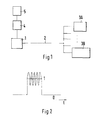
Ein Ausführungsbeispiel der Erfindung ist in der Zeichnung dargestellt und
in der nachfolgenden Beschreibung näher erläutert. Es zeigt die Figur 1 ein
erfindungsgemäßes Übertragungssystem, Fig 2 eine schematische
Modulation des Signals,
Die Ausbildung des spektralen Kammes kann jeweils in den unterschiedlichen Bitperioden unterschiedlich gewählt werden. Die spektrale Kodierung der Signale wird jeweils von einem Empfänger, der entsprechende Filtereinrichtungen besitzt, gelesen.The formation of the spectral comb can in each case different bit periods can be selected differently. The spectral Coding of the signals is done by a receiver who has appropriate filter devices read.
Der grundlegende Vorteil der vorliegenden Erfindung besteht darin, daß eine Lichtquelle zur Verfügung gestellt wird, die aktiv einen optischen Kamm mit frequenzperiodischen Spektrum erzeugt und möglichst viele äquidistante Linien bei großer integraler Laserleistung enthält. Die Laserleistung ist dabei integral über 1 mW. Die spektrale Kodierung über die Modulation des Injektionsstrom ist sehr flexible an die Übertragungsverhältnisse und an die Zahl und Performance der Empfangsseite anpaßbar. Dazu wird ein Halbleiterlaser während der Dauer einer Bitperiode moduliert. Eine Bitperiode bedeutet bei einer Bitrate von 10 Megabit pro Sekunde eine Zeitdauer von 100 ns. Innerhalb dieser Zeit muß der Halbleiterlaser frequenz- oder phasenmoduliert werden. Dazu wird dem Injektionsstrom des Halbleiterlasers ein zusätzlicher geringer, hochfrequenter Modulationstrom aufaddiert. Der Modulationstrom kann beispielsweise mit einer Frequenz von 100 MHz den Injektionsstrom modulieren. Durch die Modulation des Injektionsstroms des Halbleiterlasers entsteht im Ausgangsspektrum des Lasers ein frequenz- beziehungsweise phasenmoduliertes Ausgangsspektrum, dessen spektrale Breite durch einen Modulationsindex m gegeben ist. Dieser Modulationsindex m entspricht etwa der Anzahl der Linien. Er hängt vom Quotienten aus Frequenzhub oder Phasenhub und Modulationsfrequenz ab. Der Frequenzhub ist proportional zur Amplitude des hochfrequenten Modulationsstromes, der den Injektionsstrom mit der Modulationsfrequenz moduliert. Um bei 100 MHz Modulationsfrequenz 100 spektrale Linien zu erzeugen, muß der Frequenzhub 10 GHz betragen. Für einen solchen Modulationshub von 10 GHz ist ein zusätzlicher Modulationsstrom von wenigen mA erforderlich. Die zusätzliche Modulation des Injektionsstromes innerhalb einer Bitperiode ist für heute gebräuchliche DFB-Laser ohne weitere Probleme anwendbar. Verwendet man Fabry-Perot Laser müssen die Abstände zwischen den Longitudinal-Moden der Laseremission so eingestellt werden, daß sie dem ganzzahligen Vielfachen der Modulationsfrequenz entsprechen. Eine solche Einstellung erfolgt über Temperierung des Fabry-Perot Lasers.The basic advantage of the present invention is that a light source is provided that is actively an optical comb generated with frequency-periodic spectrum and as many equidistant as possible Contains lines with large integral laser power. The laser power is there integral over 1 mW. The spectral coding via the modulation of the Injection current is very flexible to the transmission ratios and to the Customizable number and performance of the receiving side. To do this, a Semiconductor laser modulated for the duration of a bit period. A Bit period means one at a bit rate of 10 megabits per second Duration of 100 ns. The semiconductor laser must be within this time be frequency or phase modulated. This is the injection current the semiconductor laser an additional low, high frequency Modulation current added. The modulation current can be, for example, with modulate the injection current at a frequency of 100 MHz. Through the Modulation of the injection current of the semiconductor laser occurs in the Output spectrum of the laser a frequency respectively phase-modulated output spectrum, the spectral width of which by a Modulation index m is given. This modulation index corresponds to m about the number of lines. It depends on the quotient from the frequency swing or phase shift and modulation frequency. The frequency swing is proportional to the amplitude of the high-frequency modulation current, the modulates the injection current with the modulation frequency. Around at 100 MHz modulation frequency to generate 100 spectral lines, the Frequency shift be 10 GHz. For such a modulation stroke of 10 GHz, an additional modulation current of a few mA is required. The is additional modulation of the injection current within a bit period applicable for DFB lasers in use today without further problems. When using Fabry-Perot lasers, the distances between the Longitudinal modes of laser emission are set so that they correspond to integer multiples of the modulation frequency. Such Adjustment is made by tempering the Fabry-Perot laser.
Die spektrale Kodierung in einem Übertragungssystem unter Verwendung einer modulierten Laserlichtquelle erfolgt über die Zuweisung des Abstands der periodisch spektralen Komponenten. Damit steht für jeden Empfänger ein spezieller Frequenzkamm zur Verfügung, dessen Abstand spezifisch für den entsprechenden Empfänger ist. Die Codierung erfolgt damit über die Modulationsfrequenz, die entsprechend eingestellt wird. Die Modulationsfrequenz bestimmt den Abstand der Linien voneinander. Damit könne bei diesem Übertragungsverfahren bitweise unterschiedliche Frequenzkämme erzeugt werden, deren Linienabstand typisch ist. Das Übertragungsverfahren, das mit einem besonders einfachen und kostengünstigen Sender arbeiten kann, arbeitet bis zu Bitraten von ca 10 MHz.Using spectral coding in a transmission system a modulated laser light source is done by assigning the distance the periodic spectral components. It stands for every recipient a special frequency comb is available, the distance of which is specific to the corresponding recipient. The coding is done via the Modulation frequency, which is set accordingly. The Modulation frequency determines the distance between the lines. In order to can differ bit by bit with this transmission method Frequency combs are generated, the line spacing is typical. The Transmission method that with a particularly simple and low-cost transmitter can work up to bit rates of approx. 10 MHz.
Jeder Empfänger besitzt ein optisches Filter. Nur Signale mit dem für diesen Empfänger festgelegten Kode werden optisch durchgelassen und können detektiert werden. Dabei wird im allgemeinen bei einer Filterkurve mit sin2 Verlauf auf das Maximum der zentralen Spektrallinie detektiert. Daher ist es auf einfache Art möglich einen "1" oder einen "0" zu übertragen: Bei einer 1 emittiert der Sender einen spektralen Kamm der Empfänger detektiert die zentrale Linie. Bei einer Null veschiebt man den Arbeitspunkt so, daß die Emission des spektralen Kamms um einen halben Linienabstand verschoben wird. Der Empfänger detektiert jetzt in der zentralen Position eine "0". Each receiver has an optical filter. Only signals with the code specified for this receiver are optically transmitted and can be detected. It is generally detected in a filter curve with sin 2 curve to the maximum of the central spectral line. It is therefore possible to transmit a "1" or a "0" in a simple way: With a 1, the transmitter emits a spectral comb, and the receiver detects the central line. At zero, the operating point is shifted so that the emission of the spectral comb is shifted by half a line spacing. The receiver now detects a "0" in the central position.
Die Verwendung einer aktiven Laserlichtquelle als Lichtquelle für ein CDMA
Übertragungsverfahren kann noch optimiert werden. Ohne Störung liefert
die erfindungsgemäße Laserlichtquelle sehr schmale Linien. Die
Verwendung von sehr schmalen Linien kann bei der Übertragung in
speziellen Überlagerungsfällen zu einem kompletten Auslöschen der
Information führen. Die Bitfehlerrate wird geringer, wenn die spektralen
Linien etwas verbreitert werden. Für diesen Zweck wird dem
Hochfrequenzsignal ein Phasenrauschen überlagert. Als einfachste Fall
dient dazu ein Rauschoszillator 5, der mit der Hochfequenzerzeugung in
Verbindung steht.The use of an active laser light source as a light source for a CDMA
Transmission methods can still be optimized. Deliver without interference
the laser light source according to the invention very narrow lines. The
Use of very narrow lines can result in transmission
special overlapping cases for a complete extinction of the
Lead information. The bit error rate becomes lower when the spectral
Lines are widened somewhat. For this purpose, the
High-frequency signal superimposed on a phase noise. As the simplest case
serves a
Das Übertragungsverfahren funktioniert ebenfalls unter Verwendung konventioneller Lichtquellen mit externen Modulatoren. Die Lichtleitung ist in diesem Fall nicht so groß, aber die Übertragungsmöglichkeiten entsprechen der oben ausgeführten Form.The transmission method also works using conventional light sources with external modulators. The light pipe is not so big in this case, but the transfer options correspond to the form outlined above.
Claims (11)
Applications Claiming Priority (2)
| Application Number | Priority Date | Filing Date | Title |
|---|---|---|---|
| DE19822616A DE19822616A1 (en) | 1998-05-20 | 1998-05-20 | Light source and method for the transmission of spectrally coded data |
| DE19822616 | 1998-05-20 |
Publications (2)
| Publication Number | Publication Date |
|---|---|
| EP0959576A2 true EP0959576A2 (en) | 1999-11-24 |
| EP0959576A3 EP0959576A3 (en) | 2005-02-09 |
Family
ID=7868394
Family Applications (1)
| Application Number | Title | Priority Date | Filing Date |
|---|---|---|---|
| EP99440103A Withdrawn EP0959576A3 (en) | 1998-05-20 | 1999-05-11 | Light source and method for transmitting spectrally encoded data |
Country Status (4)
| Country | Link |
|---|---|
| US (1) | US6671468B1 (en) |
| EP (1) | EP0959576A3 (en) |
| JP (1) | JP2000031940A (en) |
| DE (1) | DE19822616A1 (en) |
Families Citing this family (2)
| Publication number | Priority date | Publication date | Assignee | Title |
|---|---|---|---|---|
| DE10029336A1 (en) * | 2000-03-20 | 2002-01-03 | Sel Alcatel Ag | Broadband optical light source, use of a broadband optical light source and methods for demultiplexing |
| DE10050878B4 (en) * | 2000-10-13 | 2012-07-12 | Atmel Automotive Gmbh | Method for transmitting a plurality of information symbols |
Citations (2)
| Publication number | Priority date | Publication date | Assignee | Title |
|---|---|---|---|---|
| US4703474A (en) * | 1986-02-28 | 1987-10-27 | American Telephone And Telegraph Company, At&T Bell Laboratories | Spread spectrum code-division-multiple-access (SS-CDMA) lightwave communication system |
| EP0251748A1 (en) * | 1986-07-01 | 1988-01-07 | BRITISH TELECOMMUNICATIONS public limited company | Optical transmission system |
Family Cites Families (22)
| Publication number | Priority date | Publication date | Assignee | Title |
|---|---|---|---|---|
| US4528670A (en) * | 1983-02-25 | 1985-07-09 | At&T Bell Laboratories | Short coupled cavity laser |
| DE3509354C2 (en) * | 1985-03-15 | 1994-10-13 | Alcatel Nv | Optical communication system |
| SE451702B (en) * | 1985-04-11 | 1987-10-26 | Cyklop Ab | SET AND DEVICE FOR PACKAGING GOODS WITH A TOP COVER |
| US4768186A (en) * | 1986-02-11 | 1988-08-30 | Pirelli Cable Corporation | Multiplex transmission of analog signals by fiber optic channel |
| DE3609278A1 (en) * | 1986-03-19 | 1987-09-24 | Siemens Ag | INTEGRATED OPTICAL SEMICONDUCTOR ARRANGEMENT |
| CA1330242C (en) * | 1987-11-30 | 1994-06-14 | Gte Laboratories Incorporated | Subcarrier-multiplexed optical transmission systems using optical channel selection |
| DE3915625A1 (en) * | 1989-05-12 | 1990-11-15 | Standard Elektrik Lorenz Ag | SEMICONDUCTOR LASER |
| US5200964A (en) * | 1991-03-12 | 1993-04-06 | General Instrument Corporation | Broad linewidth lasers for optical fiber communication systems |
| US5432629A (en) * | 1992-01-17 | 1995-07-11 | Nec Corporation | Light transmission device capable of stably transmitting a modulated output light beam |
| US5325392A (en) * | 1992-03-06 | 1994-06-28 | Nippon Telegraph And Telephone Corporation | Distributed reflector and wavelength-tunable semiconductor laser |
| DE4310578C2 (en) * | 1992-03-31 | 1997-11-20 | Toshiba Kawasaki Kk | Wavelength-tunable semiconductor laser |
| GB9311169D0 (en) * | 1993-05-28 | 1993-07-14 | British Telecomm | Switching networks |
| US5587830A (en) * | 1993-05-28 | 1996-12-24 | Lucent Technologies Inc. | High capacity optical fiber network |
| JP3303515B2 (en) * | 1994-03-18 | 2002-07-22 | キヤノン株式会社 | Optical communication system and optical communication system using the same |
| IT1268058B1 (en) * | 1994-05-20 | 1997-02-20 | Cselt Centro Studi Lab Telec O | PROCEDURE AND DEVICE FOR CHECKING THE PEAK POWER OF A LASER TRANSMITTER IN DISCONTINUOUS OPTICAL TRANSMISSION SYSTEMS. |
| JPH0878790A (en) | 1994-09-07 | 1996-03-22 | Mitsubishi Electric Corp | Semiconductor light modulation device, light modulation method and manufacture of semiconductor light modulation device |
| JP3244976B2 (en) * | 1994-12-05 | 2002-01-07 | キヤノン株式会社 | Semiconductor laser driving method, semiconductor laser device, optical communication method, node, and optical communication system |
| US5631758A (en) * | 1995-10-26 | 1997-05-20 | Lucent Technologies Inc. | Chirped-pulse multiple wavelength telecommunications system |
| DE19605567A1 (en) * | 1996-02-15 | 1997-08-21 | Sel Alcatel Ag | Optical frequency-coded CDMA transmission system and optical receiver therefor |
| US5699179A (en) * | 1996-02-23 | 1997-12-16 | General Instrument Corporation Of Delaware | Cancellation of distortion components in a fiber optic link with feed-forward linearization |
| DE19620723A1 (en) * | 1996-05-23 | 1997-11-27 | Sel Alcatel Ag | Optical network unit and headquarters of an optical communication network |
| DE19723103A1 (en) * | 1997-06-03 | 1998-12-10 | Alsthom Cge Alcatel | Receiver for receiving optical signals from optical communications network |
-
1998
- 1998-05-20 DE DE19822616A patent/DE19822616A1/en not_active Withdrawn
-
1999
- 1999-05-07 JP JP11127578A patent/JP2000031940A/en active Pending
- 1999-05-11 EP EP99440103A patent/EP0959576A3/en not_active Withdrawn
- 1999-05-19 US US09/313,982 patent/US6671468B1/en not_active Expired - Fee Related
Patent Citations (2)
| Publication number | Priority date | Publication date | Assignee | Title |
|---|---|---|---|---|
| US4703474A (en) * | 1986-02-28 | 1987-10-27 | American Telephone And Telegraph Company, At&T Bell Laboratories | Spread spectrum code-division-multiple-access (SS-CDMA) lightwave communication system |
| EP0251748A1 (en) * | 1986-07-01 | 1988-01-07 | BRITISH TELECOMMUNICATIONS public limited company | Optical transmission system |
Also Published As
| Publication number | Publication date |
|---|---|
| DE19822616A1 (en) | 1999-11-25 |
| US6671468B1 (en) | 2003-12-30 |
| JP2000031940A (en) | 2000-01-28 |
| EP0959576A3 (en) | 2005-02-09 |
Similar Documents
| Publication | Publication Date | Title |
|---|---|---|
| EP0554736B1 (en) | Digital optical transmission system with a dispersing optical waveguide at the working wavelength | |
| DE69526019T2 (en) | Synchronous polarization and phase modulation for improved performance of an optical transmission system | |
| DE4402428C2 (en) | Optical data transmission system | |
| DE3319158C2 (en) | ||
| DE60221242T2 (en) | METHOD AND SYSTEM FOR TRANSMITTING A CLOCK SIGNAL VIA AN OPTICAL CONNECTION | |
| DE3232430A1 (en) | OPTICAL MESSAGE TRANSMISSION SYSTEM WITH FREQUENCY MODULATION | |
| DE2844293B2 (en) | ||
| DE69128537T2 (en) | Optical transmission system | |
| DE1226912B (en) | Communication system with a pulsed laser | |
| DE68922412T2 (en) | Optical transmitter, optical receiver and optical transmission device and control method for optical receivers. | |
| DE60126542T2 (en) | Optical transmission system and optical receiver | |
| DE10127541B4 (en) | Optical transmitter and method for generating a digital optical signal sequence | |
| DE60207618T2 (en) | Modulation method for short pulses with a low duty cycle | |
| EP0959576A2 (en) | Light source and method for transmitting spectrally encoded data | |
| DE69021601T2 (en) | Full duplex fiber optic messaging system. | |
| DE60030446T2 (en) | System and device for sending optical data | |
| DE3001892A1 (en) | FIBER-OPTICAL MESSAGE SYSTEM WITH EQUIPMENT PROTECTION | |
| DE602004002825T2 (en) | Duobinary optical transmitter | |
| EP0330190A2 (en) | Optical transmission apparatus for transmitting and receiving optical signals via an optical fibre | |
| EP1233588A2 (en) | Generation of optically coded signals | |
| DE19725714C1 (en) | Method for the optical transmission of signaling and control information in optical networks | |
| DE3503877A1 (en) | Opto-electronic arrangement for supplying an electronic circuit with light | |
| EP1137206A2 (en) | Wideband thermic light source as well as optical transmission system using it | |
| EP0977383A2 (en) | Receiver used in a transmission system for spectral coded data and method therefor | |
| DE60104020T2 (en) | EYE DIAGRAM MASK FOR OPTICAL PULSE |
Legal Events
| Date | Code | Title | Description |
|---|---|---|---|
| PUAI | Public reference made under article 153(3) epc to a published international application that has entered the european phase |
Free format text: ORIGINAL CODE: 0009012 |
|
| AK | Designated contracting states |
Kind code of ref document: A2 Designated state(s): AT BE CH CY DE DK ES FI FR GB GR IE IT LI LU MC NL PT SE |
|
| AX | Request for extension of the european patent |
Free format text: AL;LT;LV;MK;RO;SI |
|
| PUAL | Search report despatched |
Free format text: ORIGINAL CODE: 0009013 |
|
| AK | Designated contracting states |
Kind code of ref document: A3 Designated state(s): AT BE CH CY DE DK ES FI FR GB GR IE IT LI LU MC NL PT SE |
|
| AX | Request for extension of the european patent |
Extension state: AL LT LV MK RO SI |
|
| RIC1 | Information provided on ipc code assigned before grant |
Ipc: 7H 04J 14/00 B Ipc: 7H 04J 13/00 A |
|
| STAA | Information on the status of an ep patent application or granted ep patent |
Free format text: STATUS: THE APPLICATION IS DEEMED TO BE WITHDRAWN |
|
| 18D | Application deemed to be withdrawn |
Effective date: 20041201 |