EP0959292A2 - Gas fitting - Google Patents
Gas fitting Download PDFInfo
- Publication number
- EP0959292A2 EP0959292A2 EP98118966A EP98118966A EP0959292A2 EP 0959292 A2 EP0959292 A2 EP 0959292A2 EP 98118966 A EP98118966 A EP 98118966A EP 98118966 A EP98118966 A EP 98118966A EP 0959292 A2 EP0959292 A2 EP 0959292A2
- Authority
- EP
- European Patent Office
- Prior art keywords
- gas
- pressure
- shut
- ring
- valve
- Prior art date
- Legal status (The legal status is an assumption and is not a legal conclusion. Google has not performed a legal analysis and makes no representation as to the accuracy of the status listed.)
- Granted
Links
Images


Classifications
-
- F—MECHANICAL ENGINEERING; LIGHTING; HEATING; WEAPONS; BLASTING
- F17—STORING OR DISTRIBUTING GASES OR LIQUIDS
- F17C—VESSELS FOR CONTAINING OR STORING COMPRESSED, LIQUEFIED OR SOLIDIFIED GASES; FIXED-CAPACITY GAS-HOLDERS; FILLING VESSELS WITH, OR DISCHARGING FROM VESSELS, COMPRESSED, LIQUEFIED, OR SOLIDIFIED GASES
- F17C13/00—Details of vessels or of the filling or discharging of vessels
- F17C13/04—Arrangement or mounting of valves
-
- F—MECHANICAL ENGINEERING; LIGHTING; HEATING; WEAPONS; BLASTING
- F17—STORING OR DISTRIBUTING GASES OR LIQUIDS
- F17C—VESSELS FOR CONTAINING OR STORING COMPRESSED, LIQUEFIED OR SOLIDIFIED GASES; FIXED-CAPACITY GAS-HOLDERS; FILLING VESSELS WITH, OR DISCHARGING FROM VESSELS, COMPRESSED, LIQUEFIED, OR SOLIDIFIED GASES
- F17C2201/00—Vessel construction, in particular geometry, arrangement or size
- F17C2201/01—Shape
- F17C2201/0104—Shape cylindrical
- F17C2201/0109—Shape cylindrical with exteriorly curved end-piece
-
- F—MECHANICAL ENGINEERING; LIGHTING; HEATING; WEAPONS; BLASTING
- F17—STORING OR DISTRIBUTING GASES OR LIQUIDS
- F17C—VESSELS FOR CONTAINING OR STORING COMPRESSED, LIQUEFIED OR SOLIDIFIED GASES; FIXED-CAPACITY GAS-HOLDERS; FILLING VESSELS WITH, OR DISCHARGING FROM VESSELS, COMPRESSED, LIQUEFIED, OR SOLIDIFIED GASES
- F17C2201/00—Vessel construction, in particular geometry, arrangement or size
- F17C2201/01—Shape
- F17C2201/0104—Shape cylindrical
- F17C2201/0119—Shape cylindrical with flat end-piece
-
- F—MECHANICAL ENGINEERING; LIGHTING; HEATING; WEAPONS; BLASTING
- F17—STORING OR DISTRIBUTING GASES OR LIQUIDS
- F17C—VESSELS FOR CONTAINING OR STORING COMPRESSED, LIQUEFIED OR SOLIDIFIED GASES; FIXED-CAPACITY GAS-HOLDERS; FILLING VESSELS WITH, OR DISCHARGING FROM VESSELS, COMPRESSED, LIQUEFIED, OR SOLIDIFIED GASES
- F17C2205/00—Vessel construction, in particular mounting arrangements, attachments or identifications means
- F17C2205/03—Fluid connections, filters, valves, closure means or other attachments
- F17C2205/0302—Fittings, valves, filters, or components in connection with the gas storage device
- F17C2205/0323—Valves
-
- F—MECHANICAL ENGINEERING; LIGHTING; HEATING; WEAPONS; BLASTING
- F17—STORING OR DISTRIBUTING GASES OR LIQUIDS
- F17C—VESSELS FOR CONTAINING OR STORING COMPRESSED, LIQUEFIED OR SOLIDIFIED GASES; FIXED-CAPACITY GAS-HOLDERS; FILLING VESSELS WITH, OR DISCHARGING FROM VESSELS, COMPRESSED, LIQUEFIED, OR SOLIDIFIED GASES
- F17C2205/00—Vessel construction, in particular mounting arrangements, attachments or identifications means
- F17C2205/03—Fluid connections, filters, valves, closure means or other attachments
- F17C2205/0302—Fittings, valves, filters, or components in connection with the gas storage device
- F17C2205/0338—Pressure regulators
-
- F—MECHANICAL ENGINEERING; LIGHTING; HEATING; WEAPONS; BLASTING
- F17—STORING OR DISTRIBUTING GASES OR LIQUIDS
- F17C—VESSELS FOR CONTAINING OR STORING COMPRESSED, LIQUEFIED OR SOLIDIFIED GASES; FIXED-CAPACITY GAS-HOLDERS; FILLING VESSELS WITH, OR DISCHARGING FROM VESSELS, COMPRESSED, LIQUEFIED, OR SOLIDIFIED GASES
- F17C2205/00—Vessel construction, in particular mounting arrangements, attachments or identifications means
- F17C2205/03—Fluid connections, filters, valves, closure means or other attachments
- F17C2205/0302—Fittings, valves, filters, or components in connection with the gas storage device
- F17C2205/0382—Constructional details of valves, regulators
-
- F—MECHANICAL ENGINEERING; LIGHTING; HEATING; WEAPONS; BLASTING
- F17—STORING OR DISTRIBUTING GASES OR LIQUIDS
- F17C—VESSELS FOR CONTAINING OR STORING COMPRESSED, LIQUEFIED OR SOLIDIFIED GASES; FIXED-CAPACITY GAS-HOLDERS; FILLING VESSELS WITH, OR DISCHARGING FROM VESSELS, COMPRESSED, LIQUEFIED, OR SOLIDIFIED GASES
- F17C2221/00—Handled fluid, in particular type of fluid
- F17C2221/01—Pure fluids
- F17C2221/011—Oxygen
-
- F—MECHANICAL ENGINEERING; LIGHTING; HEATING; WEAPONS; BLASTING
- F17—STORING OR DISTRIBUTING GASES OR LIQUIDS
- F17C—VESSELS FOR CONTAINING OR STORING COMPRESSED, LIQUEFIED OR SOLIDIFIED GASES; FIXED-CAPACITY GAS-HOLDERS; FILLING VESSELS WITH, OR DISCHARGING FROM VESSELS, COMPRESSED, LIQUEFIED, OR SOLIDIFIED GASES
- F17C2221/00—Handled fluid, in particular type of fluid
- F17C2221/01—Pure fluids
- F17C2221/012—Hydrogen
-
- F—MECHANICAL ENGINEERING; LIGHTING; HEATING; WEAPONS; BLASTING
- F17—STORING OR DISTRIBUTING GASES OR LIQUIDS
- F17C—VESSELS FOR CONTAINING OR STORING COMPRESSED, LIQUEFIED OR SOLIDIFIED GASES; FIXED-CAPACITY GAS-HOLDERS; FILLING VESSELS WITH, OR DISCHARGING FROM VESSELS, COMPRESSED, LIQUEFIED, OR SOLIDIFIED GASES
- F17C2221/00—Handled fluid, in particular type of fluid
- F17C2221/01—Pure fluids
- F17C2221/013—Carbone dioxide
-
- F—MECHANICAL ENGINEERING; LIGHTING; HEATING; WEAPONS; BLASTING
- F17—STORING OR DISTRIBUTING GASES OR LIQUIDS
- F17C—VESSELS FOR CONTAINING OR STORING COMPRESSED, LIQUEFIED OR SOLIDIFIED GASES; FIXED-CAPACITY GAS-HOLDERS; FILLING VESSELS WITH, OR DISCHARGING FROM VESSELS, COMPRESSED, LIQUEFIED, OR SOLIDIFIED GASES
- F17C2221/00—Handled fluid, in particular type of fluid
- F17C2221/01—Pure fluids
- F17C2221/014—Nitrogen
-
- F—MECHANICAL ENGINEERING; LIGHTING; HEATING; WEAPONS; BLASTING
- F17—STORING OR DISTRIBUTING GASES OR LIQUIDS
- F17C—VESSELS FOR CONTAINING OR STORING COMPRESSED, LIQUEFIED OR SOLIDIFIED GASES; FIXED-CAPACITY GAS-HOLDERS; FILLING VESSELS WITH, OR DISCHARGING FROM VESSELS, COMPRESSED, LIQUEFIED, OR SOLIDIFIED GASES
- F17C2221/00—Handled fluid, in particular type of fluid
- F17C2221/01—Pure fluids
- F17C2221/016—Noble gases (Ar, Kr, Xe)
-
- F—MECHANICAL ENGINEERING; LIGHTING; HEATING; WEAPONS; BLASTING
- F17—STORING OR DISTRIBUTING GASES OR LIQUIDS
- F17C—VESSELS FOR CONTAINING OR STORING COMPRESSED, LIQUEFIED OR SOLIDIFIED GASES; FIXED-CAPACITY GAS-HOLDERS; FILLING VESSELS WITH, OR DISCHARGING FROM VESSELS, COMPRESSED, LIQUEFIED, OR SOLIDIFIED GASES
- F17C2223/00—Handled fluid before transfer, i.e. state of fluid when stored in the vessel or before transfer from the vessel
- F17C2223/01—Handled fluid before transfer, i.e. state of fluid when stored in the vessel or before transfer from the vessel characterised by the phase
- F17C2223/0107—Single phase
- F17C2223/0123—Single phase gaseous, e.g. CNG, GNC
-
- F—MECHANICAL ENGINEERING; LIGHTING; HEATING; WEAPONS; BLASTING
- F17—STORING OR DISTRIBUTING GASES OR LIQUIDS
- F17C—VESSELS FOR CONTAINING OR STORING COMPRESSED, LIQUEFIED OR SOLIDIFIED GASES; FIXED-CAPACITY GAS-HOLDERS; FILLING VESSELS WITH, OR DISCHARGING FROM VESSELS, COMPRESSED, LIQUEFIED, OR SOLIDIFIED GASES
- F17C2225/00—Handled fluid after transfer, i.e. state of fluid after transfer from the vessel
- F17C2225/03—Handled fluid after transfer, i.e. state of fluid after transfer from the vessel characterised by the pressure level
- F17C2225/036—Very high pressure, i.e. above 80 bars
-
- Y—GENERAL TAGGING OF NEW TECHNOLOGICAL DEVELOPMENTS; GENERAL TAGGING OF CROSS-SECTIONAL TECHNOLOGIES SPANNING OVER SEVERAL SECTIONS OF THE IPC; TECHNICAL SUBJECTS COVERED BY FORMER USPC CROSS-REFERENCE ART COLLECTIONS [XRACs] AND DIGESTS
- Y02—TECHNOLOGIES OR APPLICATIONS FOR MITIGATION OR ADAPTATION AGAINST CLIMATE CHANGE
- Y02E—REDUCTION OF GREENHOUSE GAS [GHG] EMISSIONS, RELATED TO ENERGY GENERATION, TRANSMISSION OR DISTRIBUTION
- Y02E60/00—Enabling technologies; Technologies with a potential or indirect contribution to GHG emissions mitigation
- Y02E60/30—Hydrogen technology
- Y02E60/32—Hydrogen storage
-
- Y—GENERAL TAGGING OF NEW TECHNOLOGICAL DEVELOPMENTS; GENERAL TAGGING OF CROSS-SECTIONAL TECHNOLOGIES SPANNING OVER SEVERAL SECTIONS OF THE IPC; TECHNICAL SUBJECTS COVERED BY FORMER USPC CROSS-REFERENCE ART COLLECTIONS [XRACs] AND DIGESTS
- Y10—TECHNICAL SUBJECTS COVERED BY FORMER USPC
- Y10T—TECHNICAL SUBJECTS COVERED BY FORMER US CLASSIFICATION
- Y10T137/00—Fluid handling
- Y10T137/7722—Line condition change responsive valves
- Y10T137/7781—With separate connected fluid reactor surface
- Y10T137/7793—With opening bias [e.g., pressure regulator]
- Y10T137/7809—Reactor surface separated by apertured partition
- Y10T137/781—In valve stem
- Y10T137/7811—Also through reactor surface
-
- Y—GENERAL TAGGING OF NEW TECHNOLOGICAL DEVELOPMENTS; GENERAL TAGGING OF CROSS-SECTIONAL TECHNOLOGIES SPANNING OVER SEVERAL SECTIONS OF THE IPC; TECHNICAL SUBJECTS COVERED BY FORMER USPC CROSS-REFERENCE ART COLLECTIONS [XRACs] AND DIGESTS
- Y10—TECHNICAL SUBJECTS COVERED BY FORMER USPC
- Y10T—TECHNICAL SUBJECTS COVERED BY FORMER US CLASSIFICATION
- Y10T137/00—Fluid handling
- Y10T137/8158—With indicator, register, recorder, alarm or inspection means
- Y10T137/8326—Fluid pressure responsive indicator, recorder or alarm
-
- Y—GENERAL TAGGING OF NEW TECHNOLOGICAL DEVELOPMENTS; GENERAL TAGGING OF CROSS-SECTIONAL TECHNOLOGIES SPANNING OVER SEVERAL SECTIONS OF THE IPC; TECHNICAL SUBJECTS COVERED BY FORMER USPC CROSS-REFERENCE ART COLLECTIONS [XRACs] AND DIGESTS
- Y10—TECHNICAL SUBJECTS COVERED BY FORMER USPC
- Y10T—TECHNICAL SUBJECTS COVERED BY FORMER US CLASSIFICATION
- Y10T137/00—Fluid handling
- Y10T137/8593—Systems
- Y10T137/87917—Flow path with serial valves and/or closures
Definitions
- the invention relates to a gas valve with shut-off element (shut-off valve) for the Form, pressure regulator and manometer for pressure display.
- the object of the invention is to provide a gas valve with a compact design and without the disadvantages mentioned above.
- Pressurized gas sources are, for example, pressurized gas containers, pressurized gas bottles, Pressure sockets and especially pressure gas lines.
- the compressed gas source supplies gases or gas mixtures, e.g. B. technical gases or high-purity gases such as nitrogen, Oxygen, hydrogen, synthetic air, noble gases (e.g. helium, argon, krypton, Xenon), carbon dioxide, ammonia or gas mixtures, especially test gas mixtures.
- gases or gas mixtures e.g. B. technical gases or high-purity gases such as nitrogen, Oxygen, hydrogen, synthetic air, noble gases (e.g. helium, argon, krypton, Xenon), carbon dioxide, ammonia or gas mixtures, especially test gas mixtures.
- the gas fitting contains a rotatable handle that acts as a control for one Pressure regulator is used.
- the control element is preferably a cylindrical part, which is hollow and open at both ends, or a cap.
- the control element contains a pressure measuring instrument (manometer) with pressure display.
- the manometer is preferably used to measure and display the back pressure (reduced Pressure after the pressure regulator).
- the pressure gauge has no mechanical connection.
- the gas entrance the manometer is preferably connected via a plug connection and fixed (preferably secured with a locking screw, e.g. Grub screw).
- the pressure display window is usually part of the manometer.
- the pressure display is advantageously covered with an arched window. When using a pointer instrument, it is curved or three-dimensional designed pointer preferred.
- the use of an outside (Top) arched window and a pointer with one from the pointer plane protruding part also allows good readability from the side.
- you can the window can also be part of the control element. For example, as Control element serving handle form a cap with the window. The window is then not connected to the manometer and rotates with the handle.
- the window of the pressure display is a transparent cover, e.g. B. a flat Washer, a curved part like a plastic shell or a solid plastic part, which is advantageously completely or partially curved.
- the Solid plastic part preferably acts like a lens, making it easier to read the pressure display (pressure scale) is improved.
- the window of the pressure display is preferably there made of a transparent plastic such as polystyrene, polypropylene, polycarbonate, Cycloolefin copolymer (COC), acrylic glass or polymethacylate (PMMA). Especially suitable are polycarbonate, cycloolefin copolymer (COC), acrylic glass or Polymethacylate (PMMA).
- the handle (control element of the pressure regulator) is usually opaque and is made of plastic (e.g. polypropylene, polyamide, ABS, polyester) or metal (e.g. brass, stainless steel, aluminum).
- the handle is preferred equipped with handle aids.
- Handle aids are, for example, special surface designs such as depressions, hollows, grooves, knobs or webs.
- Grip aids can also include additional parts or covers made of plastic, rubber, rubber-like Material or an elastomer, especially a thermoplastic be processable elastomer, which are attached to the handle part, for.
- the outer parts of the gas fitting are preferably made of plastic.
- the gas valve usually contains a base body on which the shut-off element and the pressure regulator is arranged.
- the main body of the gas valve is made made of a thermally formable material such as metal or plastic.
- the base body is preferably made of metal, in particular brass (preferably nickel-plated) or stainless steel, and preferably has one end (lower end) a connection, e.g. B. threaded connection or bayonet connection, for attachment to the compressed gas source (usually the compressed gas line).
- the base body is preferably cylindrical.
- the main body contains Gas channels, for example in the form of bores. Generally located the inlet for the compressed gas (high pressure side, pre-pressure) and the connection to the compressed gas source on the end face (lower end) of the standing cylindrical Body.
- a gas duct leads from the gas inlet to a shut-off element (preferably integrated on the side) and from the shut-off element to the pressure regulator (preferably in the head area of the base body).
- the pressure regulator turns it on brought the back pressure gas to an outlet, which preferably is arranged laterally in the base body.
- the gas valve combines shut-off element, pressure regulator and pressure gauge instrument (Manometer) in a confined space.
- the room is essentially a cylindrical one or cylindrical space with a preferably cap-shaped end (on the head side).
- a basic body is contained in this cylindrical space, the Shut-off element and pressure regulator.
- the gas valve appears to the viewer therefore like a part.
- shut-off element and Pressure regulator arranged between the compressed gas source and the manometer.
- the manometer, pressure regulator and shut-off element one after the other (in a row) arranged, the parts are usually in alignment.
- the cross-section of the gas valve is essentially determined by the cross-sectional area the manometer or the grip part. Of the The cross section (width) of the gas fitting is generally not larger than that Cross-section (the width) of the handle part (control element of the pressure regulator).
- the cylindrical space (or cylindrical body) is preferred rounded at one end (upper part, head). Are at this end Handle part (control element of the pressure regulator) and the window of the pressure display. Due to the rounding of the head, the handle part is easier to handle, d. H. better ergonomics.
- connection between the gas path on the back pressure side and the manometer through a central opening or bore in a central Part of the pressure regulator manufactured, for example by using a membrane rod central bore in a pressure regulator based on a diaphragm valve.
- the manometer is preferably made by a non-rotatable connector attached to the pressure regulator with an O-ring seal. The position of the manometer is fixed, for example, using a locking screw (grub screw). over the handle part (control element) adjusts the control pressure of the pressure regulator.
- the shut-off element is preferably a gas valve, e.g. B. a stuffing box valve, a slide, a rotatable disc with gas passage opening, a ball valve or diaphragm valve.
- a diaphragm valve is particularly preferred as a shut-off element used, especially in pure gas applications. Advantageous closes the shut-off element with the form. When increasing the form the closing pressure increases. This leads to increased security.
- the shut-off element is operated via an adjustment device.
- An adjustment device is, for example, a rotating ring, a sliding ring, a wheel, a lever, a Push button, a push button, a switch, a slide switch or a rocker switch.
- the adjustment device is directly or indirectly with the locking device (e.g. locking bolt of a valve) of the shut-off element.
- the shut-off element is preferably operated via a rotary ring (shut-off ring) that works like a Cylinder jacket segment formed on the cylindrical outer surface of the gas fitting is.
- the axis of rotation of the rotating ring therefore runs parallel to the longitudinal axis the gas valve.
- the rotating ring can protrude over the cylinder surface of the gas valve.
- the rotating ring is preferably on the outside with a handle provided, e.g. B. a cone-shaped piece (called a flag).
- a flag In the preferred Design of the gas valve is next to a side outlet for connection the control flag is the only one of a gas extraction line or a hose line Part that protrudes laterally from the cylindrical body of the gas valve.
- the flag is preferably interchangeable.
- the flag can for example be attached to the shut-off ring by means of a snap-in connector.
- the flag is advantageously colored for each gas type.
- the gas type-specific color Design of the interchangeable lug on the shut-off ring allows easy and flexible integrated gas type identification.
- the shut-off ring turns in an opening direction or closing movement of the shut-off element.
- gear drive Bevel gears; flat gears arranged at right angles to each other; Worm / gear), friction drive (ring / wheel), lever transmission (ring / lever) or belt drive.
- a rotary valve arranged laterally in the base body the axes of rotation of the shut-off ring and Rotary valve at right angles to each other.
- the position of the shut-off element ( On “or To “), unlike a handwheel, is clearly and directly recognizable on the basis of the setting flag / locking ring.
- the two setting positions are preferably specified by two snap-in positions and / or two stops is difficult to adjust due to the existing form.
- the gas valve is advantageous with an intermediate piece (clamping sleeve) Left hand thread at one end and a right hand thread at the other end the compressed gas source (usually a compressed gas line with threaded connection) connected, with corresponding, different threads at the gas inlet Gas valve and gas outlet of the compressed gas source are provided.
- the assembly this significantly simplifies the gas valve.
- the intermediate piece is placed between the ends to be connected and simultaneously on both Ends tightened. The original position of the gas valve is retained.
- the clamping sleeve consists of usually made of metal or plastic and is attached to the connections via O-rings sealed.
- An intermediate piece made of plastic can advantageously be designed in this way that a direct seal is possible without additional seals.
- the gas valve is characterized by a universal design that leads to a Series of advantages.
- the gas valve is suitable for all common high-purity gases (e.g. gases of purity 6.0) can be used.
- gases e.g. gases of purity 6.0
- the gas fitting can be easily adapted to the gas type by simply exchanging the position flag colored depending on the gas type and the gas type sticker. This means that only a standard type of gas fitting is required for a given pressure control range, for example a standard type for 1.5 bar, 4 bar and 10 bar maximum back pressure, with only other pressure regulators and pressure gauges generally being installed.
- the entire spectrum of gas fittings for a wide variety of applications in the laboratory / laboratory furniture area (at least 15 different types) is covered.
- the compact outer surface of the gas valve allows easy cleaning.
- the handle part serving as the control element of the pressure regulator offers an effective one Dust protection and mechanical protection for the internal parts such as the manometer.
- the handle part acts as a manometer protection cap.
- the gas valve is preferably used in the laboratory, e.g. B. as a gas sampling point for laboratory furniture.
- the gas valve is optionally available with a gas outlet the gas valve arranged metering valve.
- the metering valve is usually connected to the gas valve via a short gas line.
- gas connection pre-pressure
- gas outlet gas line piece to the metering valve behind the laboratory wall.
- the gas fitting generally has the following dimensions: diameter in the range of 35 to 80 mm, preferably 45 to 60 mm; Length (without gas connection and Clamping sleeve) in the range of 50 to 200 mm, preferably 100 to 150 mm.
- the clamping sleeve generally has an outer diameter like the gas valve (40 up to 80 mm) and a thickness usually around 20 mm.
- the gas fitting that is to say the grip part and cladding, a diameter of 50 mm.
- the handle part has a length of 50 mm (without the window of the pressure display), grip part and pressure display window result a length of 60 mm.
- the shut-off ring has a diameter here by 50 mm and a thickness by 20 mm.
- the length of the gas valve without clamping sleeve and gas connection is about 113 mm.
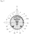
- Fig. 1 shows the gas fitting in longitudinal section.
- the base body 1 e.g. made of brass or stainless steel
- the compressed gas source e.g. compressed gas line.
- the shut-off element which preferably (as shown) consists of one Diaphragm valve exists.
- the outer end of pressure piece 4 of the diaphragm valve is flattened twice (end with a square). On this end with a square of Pressure piece 4, the gear 3 is movable (movement perpendicular to the rotary movement of the gear).
- the pressure piece 4 has an external thread, that moves in the internal thread of the retaining screw 2 when the gear 3 rotates becomes.
- a rotary movement of the gear 3 generates a lifting movement of the Pressure piece 4.
- the gear 3 does not follow the stroke movement of the Pressure piece 4.
- the teeth engage on the lower edge of the shut-off ring 22. Since the function open / close of the shut-off element by turning a quarter circle (Rotation through 90 °) of the shut-off ring 22 is to be reached, a toothing extends over a quarter of the circumference of the lower edge of the Shut-off ring 22 (see FIG. 3).
- the gear ratio of gear 3 and Teeth of the locking ring 22 is chosen accordingly.
- a translation e.g. B.
- the pressure control stage shown consists of a membrane pressure regulator with membrane rod 19, membrane 8, locking bolt 13 ', upper compression spring 18 and lower compression spring 18 '.
- the pressure control stage is made up of base body 1 and spring cover 9 enclosed.
- Spring cover 9 has an external thread at the upper end, on which the regulating screw 14 sits.
- the regulating screw 14 has one External hexagon.
- Handle part 10 has a hexagon socket in the lower area shaped recess.
- the hexagon socket of handle part 10 takes the hexagon socket from regulating screw 14.
- Adjusting screw 14 moves on the thread of spring cover 9, two Push pin 16 are moved up or down.
- the external hexagon of the regulating screw 14 moves in that of the hexagon socket of the handle part 10 formed channel.
- the lower edge of handle part 10 is slightly curved inwards.
- the edge of the handle part sits in a groove of the spring cover 9 (shown in Fig. 1).
- the pressure bolts 16 transmit the movement of the regulating screw 14 on the upper spring stop 17.
- the compressive force of the spring 18 on the diaphragm rod 19 with lower spring stop is adjusted.
- the membrane rod 19 sits down over the membrane screw 21, which is a gas channel contains, continues in the locking bolt 13 '.
- the locking bolt 13 has one square end (square).
- the square moves in the round hole of the gas channel in which a compression spring 18 'provides counter pressure.
- Pressure control unit leaves the gas at reduced pressure via a gas channel with side exit 1b on the base body 1.
- Another special feature is the Gas fitting in the area of the handle part 10, a manometer 38, which has a central Bore in the membrane rod 19 (membrane rod 19 is hollow) and one Gas channel in the membrane screw 21 with the gas channel on the reduced side Pressure (back pressure) is connected.
- the pressure gauge 38 is on the central gas inlet with the hollow membrane rod 19 via a Plug connection connected (fixation and securing with grub screw).
- the pressure gauge 38 with the pressure display 11 and pointer 11a is covered by a transparent, arched window 37 readable.
- the legibility of the print is from the front and possible from the side.
- the window 37 is attached to the manometer 38.
- the gas valve is on the clamping sleeve 24 (preferably right-hand thread and Left-hand thread) connected to the pressure line (gas source).
- the gas valve When installing in laboratory furniture, the gas valve is preferred in a laboratory furniture wall mounted so that the gas valve in the area of the (lower) cladding 23, that is below the shut-off ring 22 and above the gas outlet 1b, is installed in the laboratory furniture wall.
- the gas outlet is then behind the Laboratory furniture wall, free for the connection of a gas sampling line.
- the gas extraction line usually leads to a gas sampling valve (metering valve) that is also attached to the laboratory furniture wall and from the front like that Gas valve is operated. From the gas sampling valve leads a gas line (e.g. B. pipe or hose line) to the consumer.
- a gas line e.g. B. pipe or hose line
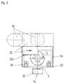
- Fig. 2 shows the gas valve of Fig. 1 in cross section along the line BB.
- the shut-off element in the base body 1, consisting of a diaphragm valve with the parts compression spring 25, locking pin 13, diaphragm 6, slide washer 5 and pressure piece 4 with gear 3, the shut-off ring 22 with the teeth 22a on the lower edge of the shut-off ring 22.
- the teeth 22a extends over a quarter of the circumference of shut-off ring 22 (extension of shut-off ring 22 in the area of toothing 22a).
- the position flag 30 is attached to the shut-off ring 22, preferably via a plug connection.
- the position flag 30 serves as a handle for actuating the shut-off element.
- the covering 23 is provided with two limiting ribs 34 at a distance of 180 °, which are attached in the region of the toothing 22a and form stops for the ends of the toothing 22a (see FIG. 3).
- the position flag 30 shown in broken lines shows the closed position ( To ”) after rotation of the flag 30 with locking ring 22 by 90 °.
- the On and The locking ring 22 is set in a noticeable manner with the aid of a locking device.
- the locking device holds the locking ring in the set position.
- the locking piece 33 is designed as a peg-shaped extension of the lower edge of the locking ring 22.
- the locking piece 33 contains a locking opening for the ball thrust piece 32.
- the ball thrust piece 32 with a compression spring is located in the receiving opening 31 in the base body 1.
- shut-off ring 22 By turning the shut-off ring 22 is over the engaging in the gear 3 Teeth 22a on the (lower) edge of the shut-off ring facing the gear 3 22 converted the rotary movement into a lifting movement.
- the relationship (Translation) the number of teeth of gear 3 and toothing 22a chosen so that the rotation of the locking ring 22 by 90 ° is a lifting movement of the pressure piece 4, which is transmitted to the locking bolt 13, for opening and closing the shut-off element is sufficient.
- a diaphragm valve, gas pressure and spring pressure of the spring act 25 in same direction, that is in the closing direction of the closing cone of Locking Bolt 13. This unusual alignment of gas pressure and spring pressure (opposite pressure directions are common) provides additional security at the shut-off element.
- Fig. 3 shows the lower part of the gas fitting.
- the interaction of shut-off ring 22 with teeth 22a and gear 3 is shown. You recognize them a quarter circle arc limited toothing 22a and extension on the Locking ring 22.
- the two limiting ribs 34 serve as a stop for the two End edges of the shut-off ring section with the toothing 22a.
- By the Interaction of the toothing 22a and gear 3 is a rotation around the Longitudinal axis of the gas valve in a rotation about an axis perpendicular to Longitudinal axis implemented.
- the holding screw 2 has recesses arranged at a 90 ° spacing on the upper side for mounting on (circles shown in Fig. 3 without numbering).
- Fig. 4 shows the gas fitting in plan view (from above; from the operator side).
- the pressure regulator is operated by means of the handle part 10.
- the handle part 10 is the manometer 38 with pressure display 11 (pressure scale and pressure pointer 11a) and a transparent, preferably curved plastic cover 37 (window) integrated, wherein handle part 10 and the pressure measuring and pressure display unit with pressure gauge 38 are mechanically separated.
- the window 37 is preferred in the central area flat. The flat area of the window bears the gas type adhesive label 12.
- Fig. 5 shows the gas valve in a side view.
- the cladding 23 contains an opening or a recess 39 as a viewing window for indicating the position (open / closed state) of the shut-off element.
- the viewing window 39 shows one of two position markings (90 ° apart) On "or
- the position flag 30 is attached to the shut-off ring 22.
- the position flag 30 is preferably attached to the shut-off ring 22 by clipping on.
- the position flag 30 advantageously has the color typical of the gas type.
- the gas fitting can be used universally (that is, for the different gases) an interchangeable position flag 30 and gas type sticker 12, the gas valve can be easily adapted to the gas type to be used.
Landscapes
- Engineering & Computer Science (AREA)
- Mechanical Engineering (AREA)
- General Engineering & Computer Science (AREA)
- Filling Or Discharging Of Gas Storage Vessels (AREA)
- Safety Valves (AREA)
- Glass Compositions (AREA)
- Mechanically-Actuated Valves (AREA)
- Measuring Volume Flow (AREA)
- Indication Of The Valve Opening Or Closing Status (AREA)
- Control Of Fluid Pressure (AREA)
Abstract
Description
Die Erfindung betrifft eine Gasarmatur mit Absperrelement (Absperrventil) für den Vordruck, Druckregler und Manometer zur Druckanzeige.The invention relates to a gas valve with shut-off element (shut-off valve) for the Form, pressure regulator and manometer for pressure display.
Labor-Gasentnahmestellen werden bisher sehr uneinheitlich aufgebaut. Die wichtigsten Baueinheiten Vordruckabsperrventil, Entnahmestellendruckregler und Hinterdruckmanometer werden als getrennte Einheiten sichtbar nebeneinander angeordnet. Eine solche Gasentnahmestelle ist beispielsweise beschrieben in DE 42 23 233 C1 (interne Bezeichnung MG 1849).Laboratory gas sampling points have so far been constructed very inconsistently. The most important Components pre-pressure shut-off valve, tapping point pressure regulator and Back pressure gauges are visible next to each other as separate units arranged. Such a gas sampling point is described, for example, in DE 42 23 233 C1 (internal designation MG 1849).
Die bekannten Gasentnahmestellen haben folgende Nachteile:
- Variantenvielfalt der Labor-Gasentnahmestellen, bedingt durch verschiedene Einbausituationen in den Labormöbeln: Tischarmatur, Energiezeilen, Energiebrücken, Abzugsarmatur (lang und schmal) und Standsäulen-Armatur,
- unübersichtliches Erscheinungsbild durch verschiedene Bedienebenen und viele Ecken und Kanten,
- eine Vielzahl von Abdichtstellen und Verschraubungen zwischen den einzelnen Bauteilen,
- zu große Abmessungen,
- ein hoher Aufwand für die Lagerhaltung durch die Teilevielfalt,
- aufwendige Wartung,
- ungenügende Ergonomie und
- zu hohes Gewicht.
- Variety of variants of the laboratory gas sampling points, due to different installation situations in the laboratory furniture: table fitting, energy lines, energy bridges, extractor fitting (long and narrow) and column fitting,
- confusing appearance due to different operating levels and many corners and edges,
- a large number of sealing points and screw connections between the individual components,
- too large dimensions,
- a high expenditure for the storage due to the variety of parts,
- time-consuming maintenance,
- insufficient ergonomics and
- too heavy weight.
Aufgabe der Erfindung besteht in der Bereitstellung einer Gasarmatur mit einer kompakten Bauweise und ohne die obengenannten Nachteile.The object of the invention is to provide a gas valve with a compact design and without the disadvantages mentioned above.
Gelöst wurde die Aufgabe durch eine Gasarmatur gemäß der Merkmale von Anspruch
1.The task was solved by a gas valve according to the features of
Druckgasquellen sind beispielsweise Druckgasbehälter, Druckgasflaschen, Druckdosen und insbesondere Druckgasleitungen. Die Druckgasquelle liefert Gase oder Gasgemische, z. B. technische Gase oder Reinstgase wie Stickstoff, Sauerstoff, Wasserstoff, synthetische Luft, Edelgase (z. B. Helium, Argon, Krypton, Xenon), Kohlendioxid, Ammoniak oder Gasgemische, insbesondere Prüfgasgemische.Pressurized gas sources are, for example, pressurized gas containers, pressurized gas bottles, Pressure sockets and especially pressure gas lines. The compressed gas source supplies gases or gas mixtures, e.g. B. technical gases or high-purity gases such as nitrogen, Oxygen, hydrogen, synthetic air, noble gases (e.g. helium, argon, krypton, Xenon), carbon dioxide, ammonia or gas mixtures, especially test gas mixtures.
Die Gasarmatur enthält ein drehbares Griffteil, das als Bedienelement für einen Druckregler dient. Vorzugsweise ist das Bedienelement ein zylinderförmiges Teil, das hohl und an beiden Enden geöffnet ist, oder eine Kappe. Das Bedienelement enthält ein Druckmeßinstrument (Manometer) mit Druckanzeige. Das Manometer dient vorzugsweise zur Messung und Anzeige des Hinterdruckes (erniedrigter Druck nach dem Druckregler). Zwischen Bedienelement für den Druckregler und Manometer besteht in der bevorzugten Bauweise keine mechanische Verbindung. Bei einer Drehung des Bedienelementes zur Einstellung des Hinterdruckes am Druckregler bleibt dadurch das Manometer in unveränderter Stellung. Bevorzugt werden Manometer mit zylindrischer Form mit einem zentralen Gaseinlaß (Gaseingang) auf der Unterseite und einer Druckanzeige an der Oberseite (Kopfseite, Bedienerseite) eingesetzt (dosenförmiges Manometer). Der Gaseingang des Manometers wird vorzugsweise über eine Steckverbindung angeschlossen und fest montiert (vorzugsweise gesichert über eine Feststellschraube, z. B. Madenschraube). Das Fenster der Druckanzeige ist in der Regel ein Teil des Manometers. Vorteilhaft ist die Druckanzeige mit einem gewölbten Fenster abgedeckt. Bei Verwendung eines Zeigerinstrumentes ist ein gebogener oder dreidimensional gestalteter Zeiger bevorzugt. Die Verwendung eines nach außen (Oberseite) gewölbten Fensters und eines Zeigers mit einem aus der Zeigerebene hervorstehenden Teiles erlaubt zusätzlich eine gute Ablesbarkeit von der Seite. Statt der Verbindung des Fensters der Druckanzeige mit dem Manometer kann das Fenster auch ein Teil des Bedienelementes sein. Beispielsweise kann das als Bedienelement dienende Griffteil mit dem Fenster eine Kappe bilden. Das Fenster ist dann nicht mit dem Manometer verbunden und dreht sich mit dem Griffteil.The gas fitting contains a rotatable handle that acts as a control for one Pressure regulator is used. The control element is preferably a cylindrical part, which is hollow and open at both ends, or a cap. The control element contains a pressure measuring instrument (manometer) with pressure display. The manometer is preferably used to measure and display the back pressure (reduced Pressure after the pressure regulator). Between the control element for the pressure regulator and In the preferred design, the pressure gauge has no mechanical connection. When turning the control element to adjust the back pressure on As a result, the pressure regulator leaves the manometer in the unchanged position. Prefers become manometers with a cylindrical shape and a central gas inlet (Gas inlet) on the bottom and a pressure gauge on the top (Head side, operator side) used (can-shaped manometer). The gas entrance the manometer is preferably connected via a plug connection and fixed (preferably secured with a locking screw, e.g. Grub screw). The pressure display window is usually part of the manometer. The pressure display is advantageously covered with an arched window. When using a pointer instrument, it is curved or three-dimensional designed pointer preferred. The use of an outside (Top) arched window and a pointer with one from the pointer plane protruding part also allows good readability from the side. Instead of connecting the window of the pressure gauge to the manometer, you can the window can also be part of the control element. For example, as Control element serving handle form a cap with the window. The window is then not connected to the manometer and rotates with the handle.
Das Fenster der Druckanzeige ist eine transparente Abdeckung, z. B. eine flache Scheibe, ein gewölbtes Teil wie eine Kunststoffschale oder ein massives Kunststoffteil, das vorteilhaft vollständig oder partiell eine gewölbte Form aufweist. Das massive Kunststoffteil wirkt vorzugsweise wie eine Linse, wodurch die Ablesbarkeit der Druckanzeige (Druckskala) verbessert wird.The window of the pressure display is a transparent cover, e.g. B. a flat Washer, a curved part like a plastic shell or a solid plastic part, which is advantageously completely or partially curved. The Solid plastic part preferably acts like a lens, making it easier to read the pressure display (pressure scale) is improved.
Das Fenster der Druckanzeige (transparente Abdeckung) besteht vorzugsweise aus einem transparenten Kunststoff wie Polystyrol, Polypropylen, Polycarbonat, Cycloolefincopolymer (COC), Acrylglas oder Polymethacylate (PMMA). Besonders geeignet sind Polycarbonat, Cycloolefincopolymer (COC), Acrylglas oder Polymethacylate (PMMA).The window of the pressure display (transparent cover) is preferably there made of a transparent plastic such as polystyrene, polypropylene, polycarbonate, Cycloolefin copolymer (COC), acrylic glass or polymethacylate (PMMA). Especially suitable are polycarbonate, cycloolefin copolymer (COC), acrylic glass or Polymethacylate (PMMA).
Das Griffteil (Bedienelement des Druckreglers) ist in der Regel undurchsichtig und wird aus Kunststoff (z. B. Polypropylen, Polyamid, ABS, Polyester) oder Metall (z. B. Messing, Edelstahl, Aluminium) hergestellt. Das Griffteil ist vorzugsweise mit Griffhilfen ausgestattet. Griffhilfen sind beispielsweise besondere Oberflächenausformungen wie Vertiefungen, Mulden, Rillen, Noppen oder Stege. Griffhilfen können auch zusätzliche Teile oder Überzüge aus Kunststoff, Gummi, gummiähnlichem Material oder einem Elastomer, insbesondere ein thermoplastisch verarbeitbares Elastomer sein, die auf dem Griffteil angebracht sind, z. B. ein Überzug, Ringe, eine Hülse oder ein Band, Noppen, Stege oder Kissen.The handle (control element of the pressure regulator) is usually opaque and is made of plastic (e.g. polypropylene, polyamide, ABS, polyester) or metal (e.g. brass, stainless steel, aluminum). The handle is preferred equipped with handle aids. Handle aids are, for example, special surface designs such as depressions, hollows, grooves, knobs or webs. Grip aids can also include additional parts or covers made of plastic, rubber, rubber-like Material or an elastomer, especially a thermoplastic be processable elastomer, which are attached to the handle part, for. B. a Cover, rings, a sleeve or a band, knobs, webs or pillows.
Die äußeren Teile der Gasarmatur wie Griffteil, Absperring und Verkleidung sind vorzugsweise aus Kunststoff. The outer parts of the gas fitting, such as the handle, shut-off ring and cladding, are preferably made of plastic.
Die Gasarmatur enthält in der Regel einen Grundkörper, an dem das Absperrelement und der Druckregler angeordnet ist. Der Grundkörper der Gasarmatur besteht aus einem thermisch formbaren Material wie Metall oder Kunststoff. Der Grundkörper besteht vorzugsweise aus Metall, insbesondere Messing (vorzugsweise vernickelt) oder Edelstahl, und weist vorzugsweise an einem Ende (unteres Ende) einen Anschluß, z. B. Gewindeanschluß oder Bajonettanschluß, zur Befestigung an der Druckgasquelle (in der Regel die Druckgasleitung) auf. Der Grundkörper ist vorzugsweise zylindrisch aufgebaut. Der Grundkörper enthält Gaskanäle, beispielsweise in Form von Bohrungen. Im allgemeinen befindet sich der Eingang für das komprimierte Gas (Hochdruckseite, Vordruck) und der Anschluß zur Druckgasquelle auf der Stirnfläche (unteres Ende) des stehenden zylindrischen Körpers. Vom Gas-Eingang führt ein Gaskanal zu einem Absperrelement (vorzugsweise seitlich integriert) und vom Absperrelement zum Druckregler (vorzugsweise im Kopfbereich des Grundkörpers). Vom Druckregler wird das auf den Hinterdruck gebrachte Gas zu einem Ausgang geführt, der vorzugsweise seitlich im Grundkörper angeordnet ist.The gas valve usually contains a base body on which the shut-off element and the pressure regulator is arranged. The main body of the gas valve is made made of a thermally formable material such as metal or plastic. Of the The base body is preferably made of metal, in particular brass (preferably nickel-plated) or stainless steel, and preferably has one end (lower end) a connection, e.g. B. threaded connection or bayonet connection, for attachment to the compressed gas source (usually the compressed gas line). The base body is preferably cylindrical. The main body contains Gas channels, for example in the form of bores. Generally located the inlet for the compressed gas (high pressure side, pre-pressure) and the connection to the compressed gas source on the end face (lower end) of the standing cylindrical Body. A gas duct leads from the gas inlet to a shut-off element (preferably integrated on the side) and from the shut-off element to the pressure regulator (preferably in the head area of the base body). The pressure regulator turns it on brought the back pressure gas to an outlet, which preferably is arranged laterally in the base body.
Die Gasarmatur vereint Absperrelement, Druckregler und Druckanzeigeinstrument (Manometer) auf engstem Raum. Der Raum ist im wesentlichen ein zylindrischer oder zylinderförmiger Raum mit vorzugsweise kappenförmigem Ende (an der Kopfseite). In diesem zylindrischen Raum ist ein Grundkörper enthalten, der Absperrelement und Druckregler aufnimmt. Die Gasarmatur erscheint dem Betrachter daher wie ein Teil. In dem zylindrischen Raum sind Absperrelement und Druckregler zwischen Druckgasquelle und Manometer angeordnet. Anders ausgedrückt, sind Manometer, Druckregler und Absperrelement hintereinander (in einer Reihe) angeordnet, wobei die Teile in der Regel in einer Flucht stehen. Das heißt der Querschnitt der Gasarmatur wird im wesentlichen durch die Querschnittsfläche des Manometers beziehungsweise des Griffteiles bestimmt. Der Querschnitt (die Breite) der Gasarmatur ist im allgemeinen nicht größer als der Querschnitt (die Breite) des Griffteiles (Bedienelement des Druckreglers). The gas valve combines shut-off element, pressure regulator and pressure gauge instrument (Manometer) in a confined space. The room is essentially a cylindrical one or cylindrical space with a preferably cap-shaped end (on the head side). A basic body is contained in this cylindrical space, the Shut-off element and pressure regulator. The gas valve appears to the viewer therefore like a part. In the cylindrical space are shut-off element and Pressure regulator arranged between the compressed gas source and the manometer. Expressed differently, are the manometer, pressure regulator and shut-off element one after the other (in a row) arranged, the parts are usually in alignment. The The cross-section of the gas valve is essentially determined by the cross-sectional area the manometer or the grip part. Of the The cross section (width) of the gas fitting is generally not larger than that Cross-section (the width) of the handle part (control element of the pressure regulator).
Der zylindrische Raum (beziehungsweise zylindrische Körper) ist vorzugsweise an einem Ende (oberes Teil, Kopf) abgerundet. An diesem Ende befinden sich Griffteil (Bedienelement des Druckreglers) und das Fenster der Druckanzeige. Durch die Abrundung des Kopfes ist eine bessere Handhabbarkeit des Griffteiles, d. h. eine bessere Ergonomie, gegeben.The cylindrical space (or cylindrical body) is preferred rounded at one end (upper part, head). Are at this end Handle part (control element of the pressure regulator) and the window of the pressure display. Due to the rounding of the head, the handle part is easier to handle, d. H. better ergonomics.
Vorzugsweise wird die Verbindung zwischen Gasweg auf der Hinterdruckseite und dem Manometer über eine zentrale Öffnung oder Bohrung in einem zentralen Teil des Druckreglers hergestellt, beispielsweise durch eine Membranstange mit zentraler Bohrung bei einem Druckregler auf Basis von einem Membranventil. Das Manometer wird vorzugsweise durch eine nicht drehbare Steckverbindung mit O-Ring-Dichtung an dem Druckregler befestigt. Die Stellung des Manometers wird beispielsweise mittels einer Feststellschraube (Madenschraube) fixiert. Über das Griffteil (Bedienelement) wird der Regeldruck des Druckreglers eingestellt.Preferably, the connection between the gas path on the back pressure side and the manometer through a central opening or bore in a central Part of the pressure regulator manufactured, for example by using a membrane rod central bore in a pressure regulator based on a diaphragm valve. The manometer is preferably made by a non-rotatable connector attached to the pressure regulator with an O-ring seal. The position of the manometer is fixed, for example, using a locking screw (grub screw). over the handle part (control element) adjusts the control pressure of the pressure regulator.
Das Absperrelement ist vorzugsweise ein Gasventil, z. B. ein Stopfbuchsventil, ein Schieber, eine drehbare Scheibe mit Gasdurchlaßöffnung, ein Kugelventil oder Membranventil. Ein Membranventil wird als Absperrelement besonders bevorzugt verwendet, insbesondere bei Reinstgas-Anwendungen. Vorteilhaft schließt das Absperrelement mit dem Vordruck. Bei Erhöhung des Vordruckes erhöht sich der Schließdruck. Dies führt zu einer erhöhten Sicherheit.The shut-off element is preferably a gas valve, e.g. B. a stuffing box valve, a slide, a rotatable disc with gas passage opening, a ball valve or diaphragm valve. A diaphragm valve is particularly preferred as a shut-off element used, especially in pure gas applications. Advantageous closes the shut-off element with the form. When increasing the form the closing pressure increases. This leads to increased security.
Das Absperrelement wird über eine Verstelleinrichtung bedient. Eine Verstelleinrichtung ist beispielsweise ein Drehring, ein Schiebering, ein Rad, ein Hebel, ein Druckknopf, eine Drucktaste, ein Schalter, ein Schiebeschalter oder ein Wippschalter. Die Verstelleinrichtung ist direkt oder indirekt mit der Schließeinrichtung (z. B. Schließbolzen eines Ventils) des Absperrelementes gekoppelt. Das Absperrelement wird bevorzugt über einen Drehring (Absperring) bedient, der wie ein Zylindermantelsegment an der zylindrischen Außenfläche der Gasarmatur ausgebildet ist. Die Drehachse des Drehringes verläuft also parallel zur Längsachse der Gasarmatur. Der Drehring kann über die Zylinderfläche der Gasarmatur herausragen. Der Drehring ist an der Außenseite vorzugsweise mit einer Griffhilfe versehen, z. B. ein zapfenförmiges Stück (Stellfahne genannt). In der bevorzugten Ausführung der Gasarmatur ist neben einem seitlichen Ausgang zum Anschluß einer Gasentnahmeleitung oder einer Schlauchleitung die Stellfahne das einzige Teil, das aus dem zylindrischen Körper der Gasarmatur seitlich herausragt. Die Stellfahne ist vorzugsweise austauschbar. Die Stellfahne kann beispielsweise mittels einer einrastenden Steckverbindung am Absperring befestigt werden. Die Stellfahne ist vorteilhaft gasartspezifisch gefärbt. Die gasartspezifische farbliche Gestaltung der austauschbaren Stellfahne am Absperring erlaubt eine einfache und flexible integrierte Gasartkennzeichnung.The shut-off element is operated via an adjustment device. An adjustment device is, for example, a rotating ring, a sliding ring, a wheel, a lever, a Push button, a push button, a switch, a slide switch or a rocker switch. The adjustment device is directly or indirectly with the locking device (e.g. locking bolt of a valve) of the shut-off element. The shut-off element is preferably operated via a rotary ring (shut-off ring) that works like a Cylinder jacket segment formed on the cylindrical outer surface of the gas fitting is. The axis of rotation of the rotating ring therefore runs parallel to the longitudinal axis the gas valve. The rotating ring can protrude over the cylinder surface of the gas valve. The rotating ring is preferably on the outside with a handle provided, e.g. B. a cone-shaped piece (called a flag). In the preferred Design of the gas valve is next to a side outlet for connection the control flag is the only one of a gas extraction line or a hose line Part that protrudes laterally from the cylindrical body of the gas valve. The The flag is preferably interchangeable. The flag can for example be attached to the shut-off ring by means of a snap-in connector. The The flag is advantageously colored for each gas type. The gas type-specific color Design of the interchangeable lug on the shut-off ring allows easy and flexible integrated gas type identification.
Eine Drehbewegung des Absperringes wird je nach Drehrichtung in eine öffnende oder schließende Bewegung des Absperrelementes übertragen. Zur Übertragung können unterschiedliche Vorrichtungen eingesetzt werden, z. B. Zahnradantrieb (Kegelzahnräder; rechtwinklig zueinander angeordnete flache Zahnräder; Schnecke/Zahnrad), Friktionsantrieb (Ring/Rad), Hebelübersetzung (Ring/Hebel) oder Riemenantrieb. Bei einem seitlich im Grundkörper angeordneten Drehventil als Absperrelement stehen im allgemeinen die Drehachsen von Absperring und Drehventil im rechten Winkel zueinander.Depending on the direction of rotation, the shut-off ring turns in an opening direction or closing movement of the shut-off element. For transmission different devices can be used, e.g. B. gear drive (Bevel gears; flat gears arranged at right angles to each other; Worm / gear), friction drive (ring / wheel), lever transmission (ring / lever) or belt drive. With a rotary valve arranged laterally in the base body the axes of rotation of the shut-off ring and Rotary valve at right angles to each other.
Die Stellung des Absperrelementes (
![]()
![]()
Die Gasarmatur wird vorteilhaft über ein Zwischenstück (Spannmuffe) mit einem Linksgewinde an einem Ende und einem Rechtsgewinde am anderen Ende mit der Druckgasquelle (in der Regel eine Druckgasleitung mit Gewindeanschluß) verbunden, wobei entsprechende, unterschiedliche Gewinde bei Gaseingang der Gasarmatur und Gasausgang der Druckgasquelle vorgesehen werden. Die Montage der Gasarmatur vereinfacht sich dadurch wesentlich. Das Zwischenstück wird zwischen die zu verbindenden Enden gebracht und gleichzeitig an beiden Enden angezogen. Die ursprüngliche Position der Gasarmatur bleibt erhalten. Die Gasarmatur kann dadurch problemlos ausgerichtet werden. Besonders vorteilhaft ist das Zwischenstück dem Querschnitt der Gasarmatur angepaßt und mit einer Griffhilfe, z. B. Griffmulden oder Rippen, ausgestattet. Die Spannmuffe besteht in der Regel aus Metall oder Kunststoff und wird über O-Ringe an den Anschlüssen abgedichtet. Ein Zwischenstück aus Kunststoff kann vorteilhaft so ausgeführt werden, daß eine direkte Abdichtung ohne zusätzliche Dichtungen möglich ist.The gas valve is advantageous with an intermediate piece (clamping sleeve) Left hand thread at one end and a right hand thread at the other end the compressed gas source (usually a compressed gas line with threaded connection) connected, with corresponding, different threads at the gas inlet Gas valve and gas outlet of the compressed gas source are provided. The assembly this significantly simplifies the gas valve. The intermediate piece is placed between the ends to be connected and simultaneously on both Ends tightened. The original position of the gas valve is retained. The This enables gas fittings to be aligned without any problems. Particularly advantageous the adapter is adapted to the cross section of the gas valve and with a Grip aid, e.g. B. recessed handles or ribs. The clamping sleeve consists of usually made of metal or plastic and is attached to the connections via O-rings sealed. An intermediate piece made of plastic can advantageously be designed in this way that a direct seal is possible without additional seals.
Die Gasarmatur zeichnet sich durch eine universelle Bauweise aus, die zu einer Reihe von Vorteilen führt.The gas valve is characterized by a universal design that leads to a Series of advantages.
Durch Einsatz einer Ganzmetallabdichtung im Bereich des direkten Gaskontaktes und Ausführung des Grundkörpers in Edelstahl oder Messing, insbesondere durch Einsatz von Membranventilen mit Hastelloy(R) -Membran bei Druckregler und Absperrelement, ist die Gasarmatur für alle gängigen Reinstgase (z. B. Gase der Reinheit 6.0) verwendbar. Durch einfachen Austausch von gasartabhängig gefärbter Stellungsfahne und dem Gasartaufkleber kann die Gasarmatur an die Gasart leicht angepaßt werden. Das bedeutet, daß für einen gegebenen Druckregelbereich nur ein Standardtyp der Gasarmatur benötigt wird, beispielsweise jeweils ein Standardtyp für 1,5 bar, 4 bar und 10 bar maximalen Hinterdruck, wobei in der Regel nur andere Druckregler und Manometer eingebaut werden. Das ganze Spektrum von Gasarmaturen für die verschiedensten Anwendungen im Laborbereich/Labormöbelbereich (mindestens 15 verschiedene Typen) wird damit abgedeckt.By using an all-metal seal in the area of direct gas contact and designing the base body in stainless steel or brass, in particular by using diaphragm valves with a Hastelloy (R) membrane for pressure regulators and shut-off elements, the gas valve is suitable for all common high-purity gases (e.g. gases of purity 6.0) can be used. The gas fitting can be easily adapted to the gas type by simply exchanging the position flag colored depending on the gas type and the gas type sticker. This means that only a standard type of gas fitting is required for a given pressure control range, for example a standard type for 1.5 bar, 4 bar and 10 bar maximum back pressure, with only other pressure regulators and pressure gauges generally being installed. The entire spectrum of gas fittings for a wide variety of applications in the laboratory / laboratory furniture area (at least 15 different types) is covered.
Die kompakte Außenfläche der Gasarmatur erlaubt eine einfache Reinigung. Das als Bedienelement des Druckreglers dienende Griffteil bietet einen effektiven Staubschutz und einen mechanischen Schutz für die innenliegenden Teile wie dem Manometer. Das Griffteil wirkt als Manometerschutzkappe. The compact outer surface of the gas valve allows easy cleaning. The The handle part serving as the control element of the pressure regulator offers an effective one Dust protection and mechanical protection for the internal parts such as the manometer. The handle part acts as a manometer protection cap.
Die Gasarmatur wird bevorzugt im Laborbereich verwendet, z. B. als Gasentnahmestelle bei Labormöbeln. Die Gasarmatur wird optional mit einem am Gasausgang der Gasarmatur angeordneten Dosierventil ausgestattet. Das Dosierventil ist in der Regel über eine kurze Gasleitung mit der Gasarmatur verbunden. Bei einer Montage in einer Labormöbelwand befinden sich Gasanschluß (Vordruck), Gasausgang und Gasleitungsstück zum Dosierventil hinter der Laborwand. Bei Kombination der Gasarmatur mit einem Dosierventil werden zwei Montageöffnungen in der Labormöbelwand benötigt gegenüber bisher mindestens drei Montageöffnungen bei üblichen Gasarmaturen.The gas valve is preferably used in the laboratory, e.g. B. as a gas sampling point for laboratory furniture. The gas valve is optionally available with a gas outlet the gas valve arranged metering valve. The metering valve is usually connected to the gas valve via a short gas line. At a Installation in a laboratory furniture wall includes gas connection (pre-pressure), gas outlet and gas line piece to the metering valve behind the laboratory wall. When combined The gas valve with a metering valve has two assembly openings in the laboratory furniture wall requires at least three assembly openings compared to previously with usual gas fittings.
Die Gasarmatur hat im allgemeinen folgende Maße: Durchmesser im Bereich von 35 bis 80 mm, vorzugsweise 45 bis 60 mm; Länge (ohne Gasanschluß und Spannmuffe) im Bereich von 50 bis 200 mm, vorzugsweise 100 bis 150 mm. Die Spannmuffe hat im allgemeinen einen Außendurchmesser wie die Gasarmatur (40 bis 80 mm) und eine Dicke gewöhnlich um 20 mm.The gas fitting generally has the following dimensions: diameter in the range of 35 to 80 mm, preferably 45 to 60 mm; Length (without gas connection and Clamping sleeve) in the range of 50 to 200 mm, preferably 100 to 150 mm. The The clamping sleeve generally has an outer diameter like the gas valve (40 up to 80 mm) and a thickness usually around 20 mm.
In der bevorzugten Ausführung hat die Gasarmatur, das heißt Griffteil und Verkleidung, einen Durchmesser von 50 mm. Das Griffteil hat hierbei eine Länge von 50 mm (ohne Fenster der Druckanzeige), Griffteil und Druckanzeigefenster ergeben hierbei eine Länge von 60 mm. Der Absperring hat hier einen Durchmesser um 50 mm und eine Dicke um 20 mm. Die Länge der Gasarmatur ohne Spannmuffe und Gasanschluß beträgt dabei etwa 113 mm.In the preferred embodiment, the gas fitting, that is to say the grip part and cladding, a diameter of 50 mm. The handle part has a length of 50 mm (without the window of the pressure display), grip part and pressure display window result a length of 60 mm. The shut-off ring has a diameter here by 50 mm and a thickness by 20 mm. The length of the gas valve without clamping sleeve and gas connection is about 113 mm.
Ein Ausführungsbeispiel wird Im folgenden anhand der Zeichnung näher beschrieben.An embodiment is described below with reference to the drawing.
Es zeigen
Fig. 1 zeigt die Gasarmatur im Längsschnitt. Der Grundkörper 1 (z. B. aus Messing
oder Edelstahl) enthält einen eingehenden Gaskanal (Eingang 1a) für kornprimiertes
Gas (z. B. 40 bar) von der Druckgasquelle (z. B. Druckgasleitung). Der
Gaskanal führt zum Absperrelement, das bevorzugt (wie gezeigt) aus einem
Membranventil besteht. Das äußere Ende von Druckstück 4 des Membranventils
ist doppelt abgeflacht (Ende mit Zweikant). Auf dieses Ende mit Zweikant von
Druckstück 4 ist das Zahnrad 3 beweglich (Bewegung senkrecht zur Drehbewegung
des Zahnrades) aufgesetzt. Das Druckstück 4 weist ein Außengewinde auf,
das im Innengewinde der Halteschraube 2 bei Drehung des Zahnrades 3 bewegt
wird. Eine Drehbewegung des Zahnrades 3 erzeugt eine Hubbewegung des
Druckstückes 4. Durch die freie Kopplung des Zahnrades 3 mit dem Druckstück 4
über den Zweikant (Mitnehmer) folgt das Zahnrad 3 nicht der Hubbewegung des
Druckstückes 4. In das Zahnrad 3 greifen die Zähne an der Unterkante des Absperringes
22. Da die Funktion Auf/Zu des Absperrelementes durch eine Viertelkreis-Drehung
(Drehung um 90°) des Absperr-Ringes 22 erreicht werden soll,
reicht eine Zahnung über ein Viertel des Kreisumfanges der unteren Kante des
Absperringes 22 (s. Fig. 3) aus. Die Übersetzung der Zähne von Zahnrad 3 und
Zähnen des Absperringes 22 ist entsprechend gewählt. Eine Übersetzung, z. B.
4:1 (Zähne von Absperring 22/Zähne von Zahnrad 3), führt zu einer leichten Bedienung
des an sich schwergängigen Absperrelementes. Abweichend von üblichen
Absperrelementen mit Membranventil wirken Federdruck und anliegender
Hinterdruck in gleicher Richtung (Schließrichtung), wodurch eine höhere Sicherheit
gewährleistet wird. Von dem Absperrelement führt ein Gaskanal zur Druckregelstufe.
Die gezeigte Druckregelstufe besteht aus einem Membran-Druckregler
mit Membranstange 19, Membran 8, Schließbolzen 13', oberer Druckfeder 18 und
unterer Druckfeder 18'. Die Druckregelstufe wird von Grundkörper 1 und Federdeckel
9 umschlossen. Federdeckel 9 trägt am oberen Ende ein Außengewinde,
auf dem die Regulierschraube 14 sitzt. Die Regulierschraube 14 besitzt einen
Außensechskant. Griffteil 10 besitzt im unteren Bereich eine als Innensechskant
geformte Aussparung. Der Innensechkant von Griffteil 10 nimmt den Außensechskant
von Regulierschraube 14 auf. Bei Drehen von Griffteil 10 wird die
Regulierschraube 14 auf dem Gewinde von Federdeckel 9 bewegt, wobei zwei
Druckbolzen 16 auf oder ab bewegt werden. Der Außensechskant von Regulierschraube
14 bewegt sich dabei in dem von dem Innensechskant der Griffteil 10
gebildeten Kanal. Der untere Rand von Griffteil 10 ist leicht nach innen gebogen.
Der Rand des Griffteiles setzt sich in eine Rille des Federdeckels 9 (in Fig. 1 ersichtlich).
Die Druckbolzen 16 übertragen die Bewegung der Regulierschraube 14
auf den oberen Federanschlag 17. Die Druckkraft der Feder 18 auf die Membranstange
19 mit unterem Federanschlag wird damit eingestellt. Die Membranstange
19 stetzt sich nach unten über die Membranschraube 21, die einen Gaskanal
enthält, in dem Schließbolzen 13' fort. Der Schließbolzen 13' besitzt ein
vierkantiges Ende (Vierkant). Der Vierkant bewegt sich in der runden Bohrung
des Gaskanals, in der eine Druckfeder 18' für einen Gegendruck sorgt. Nach der
Druckregeleinheit verläßt das Gas mit vermindertem Druck über einen Gaskanal
mit seitlichem Ausgang 1b am Grundkörper 1. Als weitere Besonderheit trägt die
Gasarmatur im Bereich des Griffteiles 10 ein Manometer 38, das über eine zentrale
Bohrung in der Membranstange 19 (Membranstange 19 ist hohl) und einen
Gaskanal in der Membranschraube 21 mit dem Gaskanal auf der Seite des verminderten
Drucks (Hinterdruck) in Verbindung steht. Das Manometer 38 ist an
dessen zentralen Gaseingang mit der hohlen Membranstange 19 über eine
Steckverbindung verbunden (Fixierung und Sicherung mittels Madenschraube).
Das Manometer 38 mit der Druckanzeige 11 und Zeiger 11a ist durch ein transparentes,
gewölbtes Fenster 37 ablesbar. Die Ablesbarkeit des Druckes ist von vorn
und von der Seite möglich. Das Fenster 37 ist am Manometer 38 befestigt.
Die Gasarmatur wird über die Spannmuffe 24 (vorzugsweise Rechtsgewinde und
Linksgewinde) mit der Druckleitung (Gasquelle) verbunden.Fig. 1 shows the gas fitting in longitudinal section. The base body 1 (e.g. made of brass
or stainless steel) contains an incoming gas channel (
Bei dem Einbau in Labormöbel wird die Gasarmatur bevorzugt in einer Labormöbelwand
montiert, so daß die Gasarmatur im Bereich der (unteren) Verkleidung
23, das heißt unterhalb des Absperringes 22 und oberhalb des Gasausganges
1b, in der Labormöbelwand angebracht ist. Der Gasausgang liegt dann hinter der
Labormöbelwand, frei für den Anschluß einer Gasentnahmeleitung. Die Gasentnahmeleitung
führt in der Regel zu einem Gasentnahmeventil (Dosierventil), das
ebenfalls in der Labormöbelwand befestigt ist und von der Vorderseite wie die
Gasarmatur bedient wird. Von dem Gasentnahmeventil führt eine Gasleitung (z.
B. Rohr- oder Schlauchleitung) zum Verbraucher.When installing in laboratory furniture, the gas valve is preferred in a laboratory furniture wall
mounted so that the gas valve in the area of the (lower)
Fig. 2 zeigt die Gasarmatur von Fig. 1 im Querschnitt entlang der Linie B-B. Man
erkennt das Absperrelement im Grundkörper 1, bestehend aus einem Membranventil
mit den Teilen Druckfeder 25, Schließbolzen 13, Membran 6, Gleitscheibe 5
und Druckstück 4 mit Zahnrad 3, den Absperring 22 mit der Verzahnung 22a an
der Unterkante des Absperringes 22. Die Verzahnung 22a erstreckt sich über ein
Viertel des Umfanges von Absperring 22 (Verlängerung des Absperringes 22 im
Bereich der Verzahnung 22a). Die Stellungsfahne 30 ist an Absperring 22, vorzugsweise
über eine Steckverbindung, angebracht. Die Stellungsfahne 30 dient
als Griff zur Betätigung des Absperrelementes. Die Verkleidung 23 ist mit zwei
Begrenzungsrippen 34 im Abstand von 180° versehen, die im Bereich der Verzahnung
22a angebracht sind und Anschläge für die Enden der Verzahnung 22a
bilden (siehe Fig. 3). Die gestrichelt gezeichnete Stellungsfahne 30 zeigt die geschlossene
Stellung (
Die
Durch Drehung des Absperringes 22 wird über die in das Zahnrad 3 greifende
Verzahnung 22a an der dem Zahnrad 3 zugewandten (unteren) Kante des Absperringes
22 die Drehbewegung in eine Hubbewegung umgesetzt. Das Verhältnis
(Übersetzung) der Anzahl der Zähne von Zahnrad 3 und Verzahnung 22a ist
so gewählt, daß der Drehung des Absperringes 22 um 90° eine Hubbewegung
des Druckstückes 4, die auf den Schließbolzen 13 übertragen wird, für ein Öffnen
und Schließen des Absperrelementes ausreicht. Bei dem gezeigten Absperrelement,
einem Membranventil, wirken Gasdruck und Federdruck der Feder 25 in
gleicher Richtung, das heißt in schließender Richtung des Schließkegels von
Schließbolzen 13. Diese unübliche Ausrichtung von Gasdruck und Federdruck
(üblich sind entgegengesetzte Druckrichtungen) sorgt für zusätzliche Sicherheit
bei dem Absperrelement.By turning the shut-
Fig. 3 zeigt das untere Teil der Gasarmatur. Das Zusammenwirken von Absperring
22 mit Verzahnung 22a und Zahnrad 3 ist dargestellt. Man erkennt die auf
einen viertelkreisbogen beschränkte Verzahnung 22a und Verlängerung an dem
Absperring 22. Die zwei Begrenzungsrippen 34 dienen als Anschlag für die beiden
Endkanten des Absperringabschnittes mit der Verzahnung 22a. Durch das
Zusammenwirken von Verzahnung 22a und Zahnrad 3 wird eine Drehung um die
Längsachse der Gasarmatur in eine Drehung um eine Achse senkrecht zur
Längsachse umgesetzt. Da das Druckstück 4 mit seinem Außengewinde in dem
Innengewinde der Halteschraube 2 geführt wird, bewirkt eine Drehung eine Auf- oder
Abbewegung (je nach Drehrichtung) des Druckstückes 4 und damit des
Schließbolzens 13. Die Befestigungsnippel 36 dienen zur Befestigung der Verkleidung
an dem Grundkörper 1. Über das Anschlußstück 35 wird die Druckgasleitung
angeschlossen.Fig. 3 shows the lower part of the gas fitting. The interaction of shut-
Die Halteschraube 2 weist an der Oberseite in 90° Abstand angeordnete Vertiefungen
für die Montage auf (in Fig. 3 gezeigte Kreise ohne Nummerierung).The holding
Fig. 4 zeigt die Gasarmatur in der Draufsicht (von oben; von der Bedienerseite).
Der Druckregler wird mittels Griffteil 10 bedient. In das Griffteil 10 ist das Manometer
38 mit Druckanzeige 11 (Druckskala und Druckzeiger 11a) und einer transparenten,
vorzugsweise gewölbten Kunststoffabdeckung 37 (Fenster) integriert,
wobei Griffteil 10 und die Druckmeß- und Druckanzeigeeinheit mit Manometer 38
mechanisch getrennt sind. Das Fenster 37 ist im mittleren Bereich vorzugsweise
flach. Der flache Bereich des Fensters trägt das Gasartklebeschild 12.Fig. 4 shows the gas fitting in plan view (from above; from the operator side).
The pressure regulator is operated by means of the
Fig. 5 die Gasarmatur in der Seitenansicht. Die Verkleidung 23 enthält einen
Durchbruch oder eine Aussparung 39 als Sichtfenster zur Stellungsanzeige
(Öffnungszustand Auf/Zu) der Absperrelementes. Das Sichtfenster 39 zeigt je
nach Stellung des Absperringes 22 eine von zwei darauf in 90° Abstand angebrachten
Stellungsmarkierungen (
- 11
- GrundkörperBasic body
- 1a1a
- GaseingangGas inlet
- 1b1b
- GasausgangGas outlet
- 22nd
- HalteschraubeRetaining screw
- 33rd
- Zahnradgear
- 44th
- DruckstückPressure piece
- 55
- Gleitscheibe (Metall, PTFE-beschichtet)Sliding washer (metal, PTFE-coated)
- 66
- Membranmembrane
- 77
- GleitringSlide ring
- 88th
- Membran mit LochMembrane with hole
- 99
- FederdeckelSpring cover
- 1010th
- Bedienelement des Druckreglers (Griffteil)Control element of the pressure regulator (handle part)
- 1111
- DruckanzeigePressure display
- 11a11a
- DruckzeigerPressure pointer
- 1212th
- Gasart-KlebeschildGas type label
- 13, 13'13, 13 '
- SchließbolzenLocking bolt
- 1414
- Stellmutter (Regulierschraube)Adjusting nut (regulating screw)
- 1515
- Dichtungpoetry
- 1616
- DruckbolzenPressure bolt
- 1717th
- oberer Federanschlagupper spring stop
- 18, 18'18, 18 '
- Federfeather
- 1919th
- Membranstange (mit unterem Federanschlag)Membrane rod (with lower spring stop)
- 2020th
- MembrandichtungMembrane seal
- 2121
- MembranschraubeMembrane screw
- 2222
- Absperr-RingShut-off ring
- 22a22a
- Verzahnung auf Absperr-RingkanteToothing on the ring edge
- 2323
- VerkleidungCladding
- 2424th
- SpannmuffeClamping sleeve
- 2525th
- DruckfederCompression spring
- 2727
- Ventilsitzdichtung Valve seat gasket
- 2929
- VentilsitzschraubeValve seat screw
- 3030th
- StellungsfahnePosition flag
- 3131
- Aufnahmeöffnung für Druckfeder und Kugel der EinrastvorrichtungOpening for compression spring and ball of the locking device
- 3232
- Kugel (Kugeldruckstück)Ball (ball thrust piece)
- 3333
- Einraststück (Verlängerung von Absperr-Ring 22)Snap-in piece (extension of shut-off ring 22)
- 3434
- Begrenzungsrippe in der VerkleidungLimiting rib in the panel
- 3535
- Anschluß zur DruckgasleitungConnection to the compressed gas line
- 3636
- BefestigungsnippelMounting nipple
- 3737
- Fenster der DruckanzeigePrint display window
- 3838
- Druckmeßinstrument (Manometer)Pressure measuring instrument (manometer)
- 3939
- Fenster oder Aussparung zur StellungsanzeigeWindow or recess for position indication
Claims (10)
Applications Claiming Priority (2)
| Application Number | Priority Date | Filing Date | Title |
|---|---|---|---|
| DE19822369 | 1998-05-19 | ||
| DE19822369A DE19822369B4 (en) | 1998-05-19 | 1998-05-19 | gas train |
Publications (3)
| Publication Number | Publication Date |
|---|---|
| EP0959292A2 true EP0959292A2 (en) | 1999-11-24 |
| EP0959292A3 EP0959292A3 (en) | 2000-08-30 |
| EP0959292B1 EP0959292B1 (en) | 2005-09-07 |
Family
ID=7868244
Family Applications (1)
| Application Number | Title | Priority Date | Filing Date |
|---|---|---|---|
| EP98118966A Expired - Lifetime EP0959292B1 (en) | 1998-05-19 | 1998-10-07 | Gas fitting |
Country Status (6)
| Country | Link |
|---|---|
| US (1) | US6009900A (en) |
| EP (1) | EP0959292B1 (en) |
| AT (1) | ATE304146T1 (en) |
| DE (2) | DE19822369B4 (en) |
| DK (1) | DK0959292T3 (en) |
| ES (1) | ES2248869T3 (en) |
Cited By (1)
| Publication number | Priority date | Publication date | Assignee | Title |
|---|---|---|---|---|
| WO2012093232A1 (en) | 2011-01-07 | 2012-07-12 | Hampiaux S.A.S. | Gas regulator for hand tools |
Families Citing this family (18)
| Publication number | Priority date | Publication date | Assignee | Title |
|---|---|---|---|---|
| US6647982B1 (en) * | 1998-06-29 | 2003-11-18 | Zaiser Lenoir E. | Gas flow device |
| US6311682B1 (en) | 1999-01-22 | 2001-11-06 | Npf Limited | Paintball guns |
| US6474325B2 (en) * | 1999-01-22 | 2002-11-05 | Npf Limited | Gas regulator |
| US6615814B1 (en) * | 1999-03-18 | 2003-09-09 | Npf Limited | Paintball guns |
| DE19913230C2 (en) * | 1999-03-23 | 2001-06-21 | Vti Ventil Technik Gmbh | Valve fitting for a pressure vessel |
| US20040194829A1 (en) * | 2002-09-19 | 2004-10-07 | Zaiser Lenoir E. | Differential pressure valve employing near-balanced pressure |
| EP1405673A1 (en) * | 2002-10-04 | 2004-04-07 | S+B International B.V. | Support plate having a service unit |
| US7617826B1 (en) | 2004-02-26 | 2009-11-17 | Ameriflo, Inc. | Conserver |
| WO2005082107A2 (en) | 2004-02-26 | 2005-09-09 | Ameriflo, Inc. | Method and apparatus for regulating fluid flow or conserving fluid flow |
| JP4619722B2 (en) * | 2004-08-11 | 2011-01-26 | 日本エア・リキード株式会社 | Container valve |
| DE502006004227D1 (en) | 2006-02-18 | 2009-08-27 | Minimax Gmbh & Co Kg | Pipe coupling for liquefied gas line with groove |
| US7650904B2 (en) * | 2007-07-11 | 2010-01-26 | Yung-Chao Huang | Pressure-regulating valve with an integrated pressure gauge |
| SI2083255T1 (en) * | 2008-01-26 | 2012-07-31 | Tescom Europ Gmbh & Co Kg | Gas extraction device |
| GB0922355D0 (en) * | 2009-12-21 | 2010-02-03 | Linde Ag | Pressure vessel |
| US8336578B2 (en) * | 2010-05-04 | 2012-12-25 | Su-Hua Tai | Quick release gas pressure regulator |
| ITPD20130258A1 (en) * | 2013-09-20 | 2015-03-21 | Huber S P A | TAP GROUP |
| FR3042584A1 (en) * | 2015-10-20 | 2017-04-21 | Air Liquide | RDI GAS DISTRIBUTION BLOCK WITH AGENCY INDICATOR DEVICE IN THE CENTER OF THE WORKING WHEEL |
| US20180128395A1 (en) * | 2016-11-10 | 2018-05-10 | Globe Fire Sprinkler Corporation | Ball valve with color-coded indicator of normal operating position |
Citations (7)
| Publication number | Priority date | Publication date | Assignee | Title |
|---|---|---|---|---|
| FR2176058A1 (en) * | 1972-03-14 | 1973-10-26 | Nussbaum & Co Ag R | Multiple fluids outlet module - esp for laboratory benches or the like |
| US4187881A (en) * | 1978-06-23 | 1980-02-12 | Acf Industries, Incorporated | Cone valve assembly |
| US4887645A (en) * | 1987-03-09 | 1989-12-19 | Ceodeux S.A. | Control station for pressurized gases |
| US5152318A (en) * | 1990-01-17 | 1992-10-06 | Man Roland Druckmaschinen Ag | Screw-in throttle valve and pressure gauge assembly |
| EP0629937A1 (en) * | 1993-06-03 | 1994-12-21 | Taema | Control unit for gas distribution and bottle provided with such unit |
| FR2735209A1 (en) * | 1995-06-08 | 1996-12-13 | Air Liquide | TAP / REGULATOR ASSEMBLY FOR GAS BOTTLE AND GAS BOTTLE PROVIDED WITH SUCH A SET |
| FR2761454A1 (en) * | 1997-04-01 | 1998-10-02 | Gce Charledave | MANOMETER TAP FOR COMPRESSED GAS BOTTLE |
Family Cites Families (5)
| Publication number | Priority date | Publication date | Assignee | Title |
|---|---|---|---|---|
| US3511266A (en) * | 1967-03-13 | 1970-05-12 | Firewel Co Inc | Shut off and pressure regulating valve |
| DE1648669C3 (en) * | 1967-04-26 | 1974-06-12 | Gesellschaft Fuer Hydraulik-Zubehoer Mbh, 6603 Sulzbach | Pressure gauge selector valve |
| US4655246A (en) * | 1983-09-30 | 1987-04-07 | Essex Industries, Inc. | Regulated gas flow control valve |
| DE4223233C1 (en) * | 1992-07-15 | 1993-09-30 | Messer Griesheim Gmbh | Laboratory gas supply point - has control and valves in same direction for standard installation |
| NL9301875A (en) * | 1993-11-01 | 1995-06-01 | Applied Power Inc | Hydraulic control valve. |
-
1998
- 1998-05-19 DE DE19822369A patent/DE19822369B4/en not_active Expired - Fee Related
- 1998-10-07 AT AT98118966T patent/ATE304146T1/en active
- 1998-10-07 DE DE59813044T patent/DE59813044D1/en not_active Expired - Lifetime
- 1998-10-07 DK DK98118966T patent/DK0959292T3/en active
- 1998-10-07 EP EP98118966A patent/EP0959292B1/en not_active Expired - Lifetime
- 1998-10-07 ES ES98118966T patent/ES2248869T3/en not_active Expired - Lifetime
- 1998-12-14 US US09/211,169 patent/US6009900A/en not_active Expired - Lifetime
Patent Citations (7)
| Publication number | Priority date | Publication date | Assignee | Title |
|---|---|---|---|---|
| FR2176058A1 (en) * | 1972-03-14 | 1973-10-26 | Nussbaum & Co Ag R | Multiple fluids outlet module - esp for laboratory benches or the like |
| US4187881A (en) * | 1978-06-23 | 1980-02-12 | Acf Industries, Incorporated | Cone valve assembly |
| US4887645A (en) * | 1987-03-09 | 1989-12-19 | Ceodeux S.A. | Control station for pressurized gases |
| US5152318A (en) * | 1990-01-17 | 1992-10-06 | Man Roland Druckmaschinen Ag | Screw-in throttle valve and pressure gauge assembly |
| EP0629937A1 (en) * | 1993-06-03 | 1994-12-21 | Taema | Control unit for gas distribution and bottle provided with such unit |
| FR2735209A1 (en) * | 1995-06-08 | 1996-12-13 | Air Liquide | TAP / REGULATOR ASSEMBLY FOR GAS BOTTLE AND GAS BOTTLE PROVIDED WITH SUCH A SET |
| FR2761454A1 (en) * | 1997-04-01 | 1998-10-02 | Gce Charledave | MANOMETER TAP FOR COMPRESSED GAS BOTTLE |
Cited By (2)
| Publication number | Priority date | Publication date | Assignee | Title |
|---|---|---|---|---|
| WO2012093232A1 (en) | 2011-01-07 | 2012-07-12 | Hampiaux S.A.S. | Gas regulator for hand tools |
| FR2970349A1 (en) * | 2011-01-07 | 2012-07-13 | Hampiaux S A S | GAS DETENDER FOR HAND TOOLS |
Also Published As
| Publication number | Publication date |
|---|---|
| DK0959292T3 (en) | 2005-12-12 |
| DE19822369A1 (en) | 1999-11-25 |
| ES2248869T3 (en) | 2006-03-16 |
| ATE304146T1 (en) | 2005-09-15 |
| US6009900A (en) | 2000-01-04 |
| EP0959292A3 (en) | 2000-08-30 |
| EP0959292B1 (en) | 2005-09-07 |
| DE59813044D1 (en) | 2005-10-13 |
| DE19822369B4 (en) | 2006-01-05 |
Similar Documents
| Publication | Publication Date | Title |
|---|---|---|
| EP0959292B1 (en) | Gas fitting | |
| DE69116029T2 (en) | Modular control panel combined with valves | |
| DE3546338C1 (en) | Valve cap for pneumatic tires providing a pressure reduction indicator | |
| EP0959293A2 (en) | Gas dispensing device from pressurized container | |
| EP0579889A1 (en) | Mixer and attachment | |
| DE102007046999B3 (en) | actuator | |
| DE3100769A1 (en) | "GAS CLEANER" | |
| DE4401787A1 (en) | Flow meter assembly | |
| CH688942A5 (en) | Device for monitoring the valve lift of a diaphragm valve. | |
| EP0139943A2 (en) | Throttle device | |
| DE102006047881B3 (en) | flow adjustment | |
| EP1255046A2 (en) | Fluid pressure cylinder, especially for use in the food industry | |
| DE8700972U1 (en) | Bourdon measuring instrument | |
| DE4102134A1 (en) | CONTACTLESSLY CONTROLLED SANITARY FITTING | |
| DE19822364A1 (en) | 0perating component for gas valve or pressure regulator | |
| DE19822367B4 (en) | Adjustment device for Absperrelelmente of compressed gas sources | |
| DE3545393C2 (en) | ||
| DE3928733A1 (en) | MANOMETER WITH SEVERAL BOURDON TUBE COILS | |
| DE3515752A1 (en) | Regulating valve for sections of piping | |
| DE19852471C2 (en) | Gas sampling system with interchangeable connection | |
| EP3867567A1 (en) | Viewing window for ventilation and air-conditioning systems and climate chambers | |
| DE2545439C2 (en) | Pressure regulator for flowing media | |
| WO1995029821A1 (en) | Connection unit to connect the valves of the two pneumatic tires in a twin tire set and compensating cap | |
| DE3938936C1 (en) | ||
| EP1014066B1 (en) | Differential Pressure Gauge |
Legal Events
| Date | Code | Title | Description |
|---|---|---|---|
| PUAI | Public reference made under article 153(3) epc to a published international application that has entered the european phase |
Free format text: ORIGINAL CODE: 0009012 |
|
| AK | Designated contracting states |
Kind code of ref document: A2 Designated state(s): AT BE CH DE DK ES FR GB IT LI LU NL SE |
|
| AX | Request for extension of the european patent |
Free format text: AL;LT;LV;MK;RO;SI |
|
| PUAL | Search report despatched |
Free format text: ORIGINAL CODE: 0009013 |
|
| AK | Designated contracting states |
Kind code of ref document: A3 Designated state(s): AT BE CH CY DE DK ES FI FR GB GR IE IT LI LU MC NL PT SE |
|
| AX | Request for extension of the european patent |
Free format text: AL;LT;LV;MK;RO;SI |
|
| 17P | Request for examination filed |
Effective date: 20010228 |
|
| AKX | Designation fees paid |
Free format text: AT BE CH DE DK ES FR GB IT LI LU NL SE |
|
| GRAP | Despatch of communication of intention to grant a patent |
Free format text: ORIGINAL CODE: EPIDOSNIGR1 |
|
| GRAS | Grant fee paid |
Free format text: ORIGINAL CODE: EPIDOSNIGR3 |
|
| GRAA | (expected) grant |
Free format text: ORIGINAL CODE: 0009210 |
|
| AK | Designated contracting states |
Kind code of ref document: B1 Designated state(s): AT BE CH DE DK ES FR GB IT LI LU NL SE |
|
| REG | Reference to a national code |
Ref country code: GB Ref legal event code: FG4D Free format text: NOT ENGLISH |
|
| REG | Reference to a national code |
Ref country code: CH Ref legal event code: EP |
|
| REF | Corresponds to: |
Ref document number: 59813044 Country of ref document: DE Date of ref document: 20051013 Kind code of ref document: P |
|
| REG | Reference to a national code |
Ref country code: DK Ref legal event code: T3 |
|
| REG | Reference to a national code |
Ref country code: SE Ref legal event code: TRGR |
|
| REG | Reference to a national code |
Ref country code: CH Ref legal event code: NV Representative=s name: BREITER + PARTNER AG PATENT - UND MARKENBUERO |
|
| RAP2 | Party data changed (patent owner data changed or rights of a patent transferred) |
Owner name: MESSER CUTTING & WELDING GMBH |
|
| REG | Reference to a national code |
Ref country code: CH Ref legal event code: PUE Owner name: MESSER CUTTING & WELDING GMBH Free format text: MESSER GRIESHEIM SCHWEISSTECHNIK GMBH + CO.#OTTO-HAHN-STRASSE 2-4#64823 GROSS-UMSTADT (DE) -TRANSFER TO- MESSER CUTTING & WELDING GMBH#OTTO-HAHN-STRASSE 2-4#64823 GROSS-UMSTADT (DE) |
|
| GBT | Gb: translation of ep patent filed (gb section 77(6)(a)/1977) |
Effective date: 20060125 |
|
| REG | Reference to a national code |
Ref country code: ES Ref legal event code: FG2A Ref document number: 2248869 Country of ref document: ES Kind code of ref document: T3 |
|
| NLT2 | Nl: modifications (of names), taken from the european patent patent bulletin |
Owner name: MESSER CUTTING & WELDING GMBH Effective date: 20060125 |
|
| ET | Fr: translation filed | ||
| REG | Reference to a national code |
Ref country code: FR Ref legal event code: CD |
|
| PLBE | No opposition filed within time limit |
Free format text: ORIGINAL CODE: 0009261 |
|
| STAA | Information on the status of an ep patent application or granted ep patent |
Free format text: STATUS: NO OPPOSITION FILED WITHIN TIME LIMIT |
|
| 26N | No opposition filed |
Effective date: 20060608 |
|
| REG | Reference to a national code |
Ref country code: CH Ref legal event code: PFA Owner name: MESSER CUTTING & WELDING GMBH Free format text: MESSER CUTTING & WELDING GMBH#OTTO-HAHN-STRASSE 2-4#64823 GROSS-UMSTADT (DE) -TRANSFER TO- MESSER CUTTING & WELDING GMBH#OTTO-HAHN-STRASSE 2-4#64823 GROSS-UMSTADT (DE) |
|
| REG | Reference to a national code |
Ref country code: FR Ref legal event code: PLFP Year of fee payment: 18 |
|
| PGFP | Annual fee paid to national office [announced via postgrant information from national office to epo] |
Ref country code: DK Payment date: 20151021 Year of fee payment: 18 |
|
| PGFP | Annual fee paid to national office [announced via postgrant information from national office to epo] |
Ref country code: CH Payment date: 20151021 Year of fee payment: 18 Ref country code: IT Payment date: 20151028 Year of fee payment: 18 |
|
| PGFP | Annual fee paid to national office [announced via postgrant information from national office to epo] |
Ref country code: BE Payment date: 20151019 Year of fee payment: 18 Ref country code: ES Payment date: 20151028 Year of fee payment: 18 Ref country code: FR Payment date: 20151023 Year of fee payment: 18 Ref country code: SE Payment date: 20151021 Year of fee payment: 18 Ref country code: AT Payment date: 20151022 Year of fee payment: 18 Ref country code: NL Payment date: 20151021 Year of fee payment: 18 |
|
| PGFP | Annual fee paid to national office [announced via postgrant information from national office to epo] |
Ref country code: LU Payment date: 20161026 Year of fee payment: 19 |
|
| PGFP | Annual fee paid to national office [announced via postgrant information from national office to epo] |
Ref country code: GB Payment date: 20161020 Year of fee payment: 19 Ref country code: DE Payment date: 20161020 Year of fee payment: 19 |
|
| PG25 | Lapsed in a contracting state [announced via postgrant information from national office to epo] |
Ref country code: BE Free format text: LAPSE BECAUSE OF NON-PAYMENT OF DUE FEES Effective date: 20161031 |
|
| REG | Reference to a national code |
Ref country code: DK Ref legal event code: EBP Effective date: 20161031 |
|
| REG | Reference to a national code |
Ref country code: CH Ref legal event code: PL |
|
| REG | Reference to a national code |
Ref country code: NL Ref legal event code: MM Effective date: 20161101 |
|
| REG | Reference to a national code |
Ref country code: AT Ref legal event code: MM01 Ref document number: 304146 Country of ref document: AT Kind code of ref document: T Effective date: 20161007 |
|
| REG | Reference to a national code |
Ref country code: FR Ref legal event code: ST Effective date: 20170630 |
|
| PG25 | Lapsed in a contracting state [announced via postgrant information from national office to epo] |
Ref country code: LI Free format text: LAPSE BECAUSE OF NON-PAYMENT OF DUE FEES Effective date: 20161031 Ref country code: FR Free format text: LAPSE BECAUSE OF NON-PAYMENT OF DUE FEES Effective date: 20161102 Ref country code: CH Free format text: LAPSE BECAUSE OF NON-PAYMENT OF DUE FEES Effective date: 20161031 |
|
| PG25 | Lapsed in a contracting state [announced via postgrant information from national office to epo] |
Ref country code: AT Free format text: LAPSE BECAUSE OF NON-PAYMENT OF DUE FEES Effective date: 20161007 Ref country code: SE Free format text: LAPSE BECAUSE OF NON-PAYMENT OF DUE FEES Effective date: 20161008 Ref country code: NL Free format text: LAPSE BECAUSE OF NON-PAYMENT OF DUE FEES Effective date: 20161101 |
|
| PG25 | Lapsed in a contracting state [announced via postgrant information from national office to epo] |
Ref country code: IT Free format text: LAPSE BECAUSE OF NON-PAYMENT OF DUE FEES Effective date: 20161007 |
|
| PG25 | Lapsed in a contracting state [announced via postgrant information from national office to epo] |
Ref country code: DK Free format text: LAPSE BECAUSE OF NON-PAYMENT OF DUE FEES Effective date: 20161031 |
|
| REG | Reference to a national code |
Ref country code: BE Ref legal event code: MM Effective date: 20161031 |
|
| REG | Reference to a national code |
Ref country code: DE Ref legal event code: R119 Ref document number: 59813044 Country of ref document: DE |
|
| PG25 | Lapsed in a contracting state [announced via postgrant information from national office to epo] |
Ref country code: ES Free format text: LAPSE BECAUSE OF FAILURE TO SUBMIT A TRANSLATION OF THE DESCRIPTION OR TO PAY THE FEE WITHIN THE PRESCRIBED TIME-LIMIT Effective date: 20050907 |
|
| GBPC | Gb: european patent ceased through non-payment of renewal fee |
Effective date: 20171007 |
|
| PG25 | Lapsed in a contracting state [announced via postgrant information from national office to epo] |
Ref country code: DE Free format text: LAPSE BECAUSE OF NON-PAYMENT OF DUE FEES Effective date: 20180501 Ref country code: GB Free format text: LAPSE BECAUSE OF NON-PAYMENT OF DUE FEES Effective date: 20171007 Ref country code: LU Free format text: LAPSE BECAUSE OF NON-PAYMENT OF DUE FEES Effective date: 20171007 |
|
| REG | Reference to a national code |
Ref country code: ES Ref legal event code: FD2A Effective date: 20181116 |
|
| RIC2 | Information provided on ipc code assigned after grant |
Ipc: F17C 13/04 20060101AFI19990916BHEP Ipc: B01L 9/02 20060101ALI19990916BHEP |
|
| PG25 | Lapsed in a contracting state [announced via postgrant information from national office to epo] |
Ref country code: ES Free format text: LAPSE BECAUSE OF FAILURE TO SUBMIT A TRANSLATION OF THE DESCRIPTION OR TO PAY THE FEE WITHIN THE PRESCRIBED TIME-LIMIT Effective date: 20161008 |