EP0959281B1 - Vakuumentlastungsventil für einen Abwasserauffangbehälter - Google Patents
Vakuumentlastungsventil für einen Abwasserauffangbehälter Download PDFInfo
- Publication number
- EP0959281B1 EP0959281B1 EP99710003A EP99710003A EP0959281B1 EP 0959281 B1 EP0959281 B1 EP 0959281B1 EP 99710003 A EP99710003 A EP 99710003A EP 99710003 A EP99710003 A EP 99710003A EP 0959281 B1 EP0959281 B1 EP 0959281B1
- Authority
- EP
- European Patent Office
- Prior art keywords
- disk
- openings
- holding tank
- assembly
- valve
- Prior art date
- Legal status (The legal status is an assumption and is not a legal conclusion. Google has not performed a legal analysis and makes no representation as to the accuracy of the status listed.)
- Expired - Lifetime
Links
- 239000010865 sewage Substances 0.000 title claims description 26
- 239000004033 plastic Substances 0.000 claims description 12
- 229920003023 plastic Polymers 0.000 claims description 12
- XLYOFNOQVPJJNP-UHFFFAOYSA-N water Substances O XLYOFNOQVPJJNP-UHFFFAOYSA-N 0.000 claims description 9
- 230000001012 protector Effects 0.000 claims description 8
- 239000000463 material Substances 0.000 claims description 6
- 239000004743 Polypropylene Substances 0.000 claims description 5
- 239000013536 elastomeric material Substances 0.000 claims description 5
- -1 polypropylene Polymers 0.000 claims description 5
- 229920001155 polypropylene Polymers 0.000 claims description 5
- 230000002093 peripheral effect Effects 0.000 claims description 4
- 230000002411 adverse Effects 0.000 claims description 2
- 230000000694 effects Effects 0.000 description 3
- 230000002452 interceptive effect Effects 0.000 description 2
- 239000007788 liquid Substances 0.000 description 2
- 239000002184 metal Substances 0.000 description 2
- 244000043261 Hevea brasiliensis Species 0.000 description 1
- 229920000459 Nitrile rubber Polymers 0.000 description 1
- 239000004677 Nylon Substances 0.000 description 1
- 230000001594 aberrant effect Effects 0.000 description 1
- 239000000853 adhesive Substances 0.000 description 1
- 230000001070 adhesive effect Effects 0.000 description 1
- 238000010276 construction Methods 0.000 description 1
- 230000007797 corrosion Effects 0.000 description 1
- 238000005260 corrosion Methods 0.000 description 1
- 238000005516 engineering process Methods 0.000 description 1
- 239000004744 fabric Substances 0.000 description 1
- 239000011152 fibreglass Substances 0.000 description 1
- 239000012530 fluid Substances 0.000 description 1
- 238000002347 injection Methods 0.000 description 1
- 239000007924 injection Substances 0.000 description 1
- 238000007689 inspection Methods 0.000 description 1
- 238000009434 installation Methods 0.000 description 1
- 238000000034 method Methods 0.000 description 1
- 238000012986 modification Methods 0.000 description 1
- 230000004048 modification Effects 0.000 description 1
- 229920003052 natural elastomer Polymers 0.000 description 1
- 229920001194 natural rubber Polymers 0.000 description 1
- 230000009972 noncorrosive effect Effects 0.000 description 1
- 229920001778 nylon Polymers 0.000 description 1
- 239000011347 resin Substances 0.000 description 1
- 229920005989 resin Polymers 0.000 description 1
- 229920003051 synthetic elastomer Polymers 0.000 description 1
- 239000005061 synthetic rubber Substances 0.000 description 1
Images


Classifications
-
- F—MECHANICAL ENGINEERING; LIGHTING; HEATING; WEAPONS; BLASTING
- F16—ENGINEERING ELEMENTS AND UNITS; GENERAL MEASURES FOR PRODUCING AND MAINTAINING EFFECTIVE FUNCTIONING OF MACHINES OR INSTALLATIONS; THERMAL INSULATION IN GENERAL
- F16K—VALVES; TAPS; COCKS; ACTUATING-FLOATS; DEVICES FOR VENTING OR AERATING
- F16K24/00—Devices, e.g. valves, for venting or aerating enclosures
- F16K24/06—Devices, e.g. valves, for venting or aerating enclosures for aerating only
-
- B—PERFORMING OPERATIONS; TRANSPORTING
- B63—SHIPS OR OTHER WATERBORNE VESSELS; RELATED EQUIPMENT
- B63B—SHIPS OR OTHER WATERBORNE VESSELS; EQUIPMENT FOR SHIPPING
- B63B29/00—Accommodation for crew or passengers not otherwise provided for
- B63B29/16—Soil water discharges
-
- F—MECHANICAL ENGINEERING; LIGHTING; HEATING; WEAPONS; BLASTING
- F16—ENGINEERING ELEMENTS AND UNITS; GENERAL MEASURES FOR PRODUCING AND MAINTAINING EFFECTIVE FUNCTIONING OF MACHINES OR INSTALLATIONS; THERMAL INSULATION IN GENERAL
- F16K—VALVES; TAPS; COCKS; ACTUATING-FLOATS; DEVICES FOR VENTING OR AERATING
- F16K15/00—Check valves
- F16K15/14—Check valves with flexible valve members
- F16K15/1402—Check valves with flexible valve members having an integral flexible member cooperating with a plurality of seating surfaces
-
- F—MECHANICAL ENGINEERING; LIGHTING; HEATING; WEAPONS; BLASTING
- F16—ENGINEERING ELEMENTS AND UNITS; GENERAL MEASURES FOR PRODUCING AND MAINTAINING EFFECTIVE FUNCTIONING OF MACHINES OR INSTALLATIONS; THERMAL INSULATION IN GENERAL
- F16K—VALVES; TAPS; COCKS; ACTUATING-FLOATS; DEVICES FOR VENTING OR AERATING
- F16K15/00—Check valves
- F16K15/14—Check valves with flexible valve members
- F16K15/148—Check valves with flexible valve members the closure elements being fixed in their centre
-
- Y—GENERAL TAGGING OF NEW TECHNOLOGICAL DEVELOPMENTS; GENERAL TAGGING OF CROSS-SECTIONAL TECHNOLOGIES SPANNING OVER SEVERAL SECTIONS OF THE IPC; TECHNICAL SUBJECTS COVERED BY FORMER USPC CROSS-REFERENCE ART COLLECTIONS [XRACs] AND DIGESTS
- Y10—TECHNICAL SUBJECTS COVERED BY FORMER USPC
- Y10T—TECHNICAL SUBJECTS COVERED BY FORMER US CLASSIFICATION
- Y10T137/00—Fluid handling
- Y10T137/7504—Removable valve head and seat unit
-
- Y—GENERAL TAGGING OF NEW TECHNOLOGICAL DEVELOPMENTS; GENERAL TAGGING OF CROSS-SECTIONAL TECHNOLOGIES SPANNING OVER SEVERAL SECTIONS OF THE IPC; TECHNICAL SUBJECTS COVERED BY FORMER USPC CROSS-REFERENCE ART COLLECTIONS [XRACs] AND DIGESTS
- Y10—TECHNICAL SUBJECTS COVERED BY FORMER USPC
- Y10T—TECHNICAL SUBJECTS COVERED BY FORMER US CLASSIFICATION
- Y10T137/00—Fluid handling
- Y10T137/7722—Line condition change responsive valves
- Y10T137/7837—Direct response valves [i.e., check valve type]
- Y10T137/7838—Plural
- Y10T137/7839—Dividing and recombining in a single flow path
- Y10T137/784—Integral resilient member forms plural valves
-
- Y—GENERAL TAGGING OF NEW TECHNOLOGICAL DEVELOPMENTS; GENERAL TAGGING OF CROSS-SECTIONAL TECHNOLOGIES SPANNING OVER SEVERAL SECTIONS OF THE IPC; TECHNICAL SUBJECTS COVERED BY FORMER USPC CROSS-REFERENCE ART COLLECTIONS [XRACs] AND DIGESTS
- Y10—TECHNICAL SUBJECTS COVERED BY FORMER USPC
- Y10T—TECHNICAL SUBJECTS COVERED BY FORMER US CLASSIFICATION
- Y10T137/00—Fluid handling
- Y10T137/7722—Line condition change responsive valves
- Y10T137/7837—Direct response valves [i.e., check valve type]
- Y10T137/7879—Resilient material valve
- Y10T137/7888—With valve member flexing about securement
- Y10T137/789—Central mount
-
- Y—GENERAL TAGGING OF NEW TECHNOLOGICAL DEVELOPMENTS; GENERAL TAGGING OF CROSS-SECTIONAL TECHNOLOGIES SPANNING OVER SEVERAL SECTIONS OF THE IPC; TECHNICAL SUBJECTS COVERED BY FORMER USPC CROSS-REFERENCE ART COLLECTIONS [XRACs] AND DIGESTS
- Y10—TECHNICAL SUBJECTS COVERED BY FORMER USPC
- Y10T—TECHNICAL SUBJECTS COVERED BY FORMER US CLASSIFICATION
- Y10T137/00—Fluid handling
- Y10T137/7722—Line condition change responsive valves
- Y10T137/7837—Direct response valves [i.e., check valve type]
- Y10T137/7897—Vacuum relief type
Definitions
- a pumpout pump is provided which is connected up to a sewage holding tank (typically of plastic) in the boat, and quickly pumps all of the sewage out of the tank.
- Most commercial pumps for these pumpout stations have a capacity of up to about 151 liters per minute (40 gallons per minute), although capacities of as high as 170 liters per minute may be expected in the future.
- the pump operator When such pumps are operated, it is difficult for the pump operator to know exactly when all the sewage has been pumped out of the holding tank, and the pump may stay in operation for a significant period of time, often up to about 30 seconds, after the tank has already been emptied. It has been recognized that this can exert a substantial strain on the holding tank, and can result in damage to the tank, or an implosion. Damage to the tank may result in leakage of sewage into the environment, obviously a highly undesirable event.
- the vacuum relief valve assembly according to the present invention substantially prevents a "spitting" effect which is caused by impacts on the holding tank when full.
- Other relief valves often allow liquid to exit the valve when the tank is full and impacted with a 10-g load; the vacuum relief valve assembly according to the present invention substantially prevents this from occurring.
- the vacuum relief assembly according to the present invention is capable of providing sufficient air flow into the holding tank so that if the holding tank is emptied by a 170 liter per minute pump remaining in operation for 30 seconds after the plastic holding tank has been emptied, no damage to the holding tank ensues.
- a boat assembly comprising the following components: A boat hull defining an interior boat volume. A toilet within the interior boat volume. A sewage holding tank operatively connected to the toilet, and also within the interior boat volume, the tank having an inside. An outlet conduit from the holding tank, and including a dockside pumpout fitting. An indicator of the fullness of the holding tank at at least one level of fullness thereof. A gas vent from the holding tank.
- a vacuum relief valve assembly for the holding tank to prevent adverse consequences associated with a vacuum condition in the tank
- the vacuum relief valve assembly comprising a valve body with a valve body surface operatively connected to the tank and having a plurality of openings formed therein, and a flexible valve disk covering the openings adjacent the inside of the tank, and uncovering openings to allow air flow therethrough substantially only when a vacuum condition exists inside the tanks, wherein said vacuum relief valve assembly further comprises a support disk mounted in contact with said flexible valve disk and providing a force on said flexible valve disk to releasably maintain said flexible valve disk in a position covering said openings.
- the vacuum relief valve assembly is preferably constructed and configured so that the opening when the vacuum inside the holding tank is as low as about 5-12.5 cm (2-5 inches) of water (e.g. about 5-7.5 cm (2-3 inches) of water) and substantially prevents the "spitting" effect.
- the vacuum relief valve assembly also preferably comprises the support disk which acts to releasably hold the valve disk into a position covering the openings.
- both the flexible valve disk and the support disk are substantially circular disks with the support disk having a diameter less than that of the flexible valve disk.
- a fastener assembly such as a nut, bolt, and washer, is preferably provided to hold the disks in operative association with the valve body surface.
- the vacuum relief valve assembly may also comprise a splash protector which is mounted to the valve body on the opposite side from the disks as the openings.
- the plurality of openings comprises a plurality of openings of at least two different cross sectional areas including smaller cross sectional area openings around the periphery of the valve body.
- the smaller cross sectional area openings are circular, and the difference in diameter between the valve disk and the support disk is approximately equal to the radius of the small openings.
- the flexible valve disk is preferably of an elastomeric material having a shore A durometer of about 50-70 (e.g. about 60) and a thickness of about 1.4-1.9 mm (.055-.075 inches).
- the support disk comprises, or is equivalent to, a polypropylene disk having a thickness of between about 0.25-0.50 mm (.010-.020 inches).
- the flexible valve disk preferably has a diameter of between about 4.7-5.2 cm (1.85-2.05 inches), and the support disk preferably has a diameter of between about 4.2-4.95 cm (1 .65-1.95 inches).
- a sewage holding tank assembly comprising the following components: A plastic sewage holding tank having a top and a bottom, a hollow interior, and an exterior. An outlet conduit from the holding tank and including a dockside pumpout fitting. A vent for the holding tank, adjacent the top thereof for allowing passage of gas under pressure from the tank to the exterior thereof. An inlet conduit for feeding sewage into the holding tank.
- a vacuum relief valve assembly mounted to the holding tank top for allowing passage of air from exterior of the tank to the interior of the tank when a significant vacuum condition exists within the tank
- the vacuum relief valve assembly comprising a valve body with a valve body surface operatively connected to the tank and having a plurality of openings formed therein, and a flexible valve disk covering the openings adjacent the inside of the tank, and uncovering openings to allow air flow therethrough substantially only when a vacuum condition exists inside the tank
- said vacuum relief valve assembly further comprises a support disk mounted in contact with said flexible valve disk and providing a force on said flexible valve disk to releasably maintain said flexible valve disk in a position covering said openings.
- the vacuum relief valve assembly is mounted to the holding tank by a peripheral upper lip on the valve body, substantially all of the valve body disposed within the tank hollow interior. Other details of the vacuum relief valve assembly are preferably as described above.
- a vacuum relief valve assembly per se, which acts as a vacuum relief device, is provided.
- the vacuum relief valve assembly comprises the following elements: A valve body comprising a tubular element having an open top (first end) and an open bottom (second end), a valve body surface disposed between the top and bottom and having a plurality of openings formed therein.
- a flexible valve disk having a substantially circular configuration covering the opening adjacent the second end of the valve body wherein the flexible valve disk opens with a vacuum on one side.
- a fastener assembly A support disk of relatively stiff material engaging the flexible valve disk and releasably holding the flexible valve disk in a position covering the openings wherein the support disk is held by said fastener assembly.
- the support disk is entrapped within the valve body surface.
- the support disk preferably has a diameter about 85-96% that of the valve disk, and the valve body preferably is made of plastic.
- a boat assembly according to the present invention of claim 12 is shown generally by reference numeral 10 in FIGURE 1. It includes a boat hull 11 which defines an interior boat volume (perhaps with other structure such as a deck 12 and a super structure above the deck).
- a toilet 14 is mounted within the interior boat volume (e.g. on deck 12), and is connected by a hose 15 or the like to an inlet 16 to a plastic holding tank 17.
- the holding tank 17 has a top 18, closed side walls 19, and a bottom 20, and is also mounted within the interior boat volume (typically below the deck 12).
- the holding tank 17 has an outlet 21 which is connected to an outlet conduit 22.
- the outlet conduit 22 includes at least one branch 23 which is connected to a dockside pumpout fitting 24 (e.g. associated with deck 12).
- the outlet conduit 22 can also have a second branch 25 which is connected to a small pump 26 also mounted within the interior boat volume, which in turn is connected by a hose 27, typically having a vented loop 28, to a seacock 29.
- the vented loop 28 is vented as indicated by vent line 30 and vent opening 31 in hull 11.
- a gas vent line 33 is preferably provided, which may have a filter 34 therein, and a vent opening 35 in the hull 11.
- an indicator 37 of the fullness of the tank 17 at at least one fullness level thereof, is provided.
- the indicator 37 may, for example, be a Tankwatcho® level indicator sold by Sealand Technology, Inc. of Big Prairie, Ohio.
- the indicator 37 typically at least indicates a three-quarters fullness level of the tank 17, and preferably also an approximately full level.
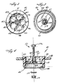
- the vacuum relief valve assembly 40 includes a substantially tubular valve body 41, preferably of a relatively rigid and tough plastic, such as injection molded in one piece from ABS.
- Body 41 includes a first (top) end 42 and a second (bottom) end 43, both of which are substantially open.
- the body 41 has a peripheral lip 44 adjacent the top end 42 thereof which facilitates mounting of the vacuum relief valve assembly 40 in the opening 39 (see FIGURE 4) of the top 18 of the holding tank 17. Any other mounting components can be utilized that are desired, such as an interference fit between the outside circumference of the valve body 41 and the opening 39, or extraneous fasteners, adhesive, or the like.
- the peripheral lip or ring 44 mounts the vacuum relief valve assembly 40 so that substantially all of the body 41 us within the interior volume of the tank 17, as seen in FIGURE 4.
- the vacuum relief valve assembly 40 further comprises a valve body surface 45 (see FIGURES 2 and 4) between the ends 42, 43 of the body 41 and typically integral therewith, and having a plurality of openings 46, 47 therein.
- a valve body surface 45 see FIGURES 2 and 4
- the ends 42, 43 of the body 41 and typically integral therewith, and having a plurality of openings 46, 47 therein.
- at least two different sized sets of openings 46, 47 are provided, larger openings 46 which extend substantially all the way from the center of the surface 45 toward the periphery, and the smaller openings 47 disposed between the larger openings 46 adjacent the periphery.
- the openings 47 are of a smaller diameter than the openings 46, and preferably both the openings 46, 47 are circular, although other shapes of openings (including slits, rings, polygons, arcs, or the like) may be utilized.
- the openings 47 may have a diameter of about 6.4 mm (a quarter of an inch) while the openings
- the valve body 41 also preferably includes a central tube 49 which extends upwardly from the surface 45 to substantially even with the top 42 of the body 41, as seen most clearly in FIGURE 4.
- the tube 49 has a central bore 50 which is associated with a fastener system 51 (see FIGURE 4).
- the fastener assembly 51 is for holding other valve components (as will be hereinafter described) to the body 41.
- the fastener assembly 51 comprises a bolt having a head 52 and a screw threaded shank 53, an internal threaded nut 54 for cooperation with the shank 53, and a metal washer 55.
- the bolt 52, 53 and nut 54 also are preferably made of metal although they (and the washer 55) may be made of hard plastic in some circumstances.
- the vacuum relief valve assembly 40 further comprises a flexible valve disk 60 (seen most clearly in FIGURES 3, 5, and 6) which covers the openings 46, 47 at the bottom-most face of the surface 45 as seen in FIGURE 4. That bottom-most face, 59 in FIGURE 4, preferably is slightly radiused (e.g. forming a spherical segment based upon an arc/sphere having a radius of about 11.4-15.2 cm (4.5-6 inches), e.g. about 13.66 cm (5.38 inches)).
- the flexible valve disk 60 preferably comprises a substantially circular disk of an elastomeric material, such as elastomeric plastic, synthetic rubber, or natural rubber. In the preferred embodiment the material of flexible valve disk 60 is nitrile rubber.
- the flexible valve disk 60 preferably has a Shore A durometer of between about 50-70 (e.g. about 60).
- flexible valve disk 60 has a diameter of about 4.7-5.2 cm (1.85-2.05 inches) (e.g. about 5 cm (1.94 inches)), with a central opening 62 therein having a diameter of about 6.3 mm (a quarter of an inch), for receipt of the shank 53 of the fastener assembly 51.
- the flexible valve disk 60 has a thickness of between about 1.4-1.9 mm (.055-.075 inches) (e.g. about 1.6 mm (.063 inches)).
- a support disk 61 is provided, as seen in FIGURES 3, 7 and 8.
- the support disk 61 preferably has a circular configuration and is in the form of a disk, as seen in FIGURES 3, and 7.
- Disk 61 is preferably flexible, but made of a relatively rigid material, such as a relatively rigid plastic such as polypropylene.
- the disk 61 has a diameter that is between about 85-96% of the diameter of the valve disk 60.
- the disk 61 has a diameter ofbetween about 4.2-4.95 cm (1.65-1.95 inches), e.g. about 4.6 cm (1.81 inches), or about 93-94% that of the flexible valve disk 60.
- the support disk 61 when tightened into contact with the shank 53 passing through the opening 63 (FIGURE 7) and tightened by the nut 54, holds the flexible valve disk 60 against the surface 59, covering the openings 46, 47.
- the support disk 61 has sufficient flexibility so that when a vacuum condition of about 5-12.5 cm (2-5 inches) of water (or greater) e.g. about 5-7.5 cm (2-3 inches) of water (or greater) exists in the tank 17 both the support disk 61 and the flexible valve disk 60 will be deformed by air rushing through at least some of the openings 46, 47 to equalize the pressure in the tank 17.
- the support disk 61 (as seen in FIGURE 8) has a thickness of about 0.25-0.50 mm (.01-.02 inches) (e.g. about 0.38 mm (.015 inches)).
- the valve body 41 may also include a ring-shaped channel 66 (see FIGURE 4) which can hold the splash protector disk 67 (see FIGURE 9) to protect the components 53-55, 61, and 60 from sewage splashing thereon, and facilitating corrosion thereof, or interfering with the performance thereof.
- the splash protector 67 which is mounted in the ring shaped channel 66 on the opposite side of the flexible valve disk 60 from the support surface 45, may be a disk of any material which allows the substantially free passage of air therethrough, but will substantially prevent liquid from splashing up onto the components 53-55, 61, 60.
- the protector disk 67 may be a stiff cloth disk, woven or non-woven, made of a non-corrosive material, such as nylon, fiberglass, or the like, and if desired partially impregnated with resin (while not interfering with its ability to pass air therethrough in an effective manner) to enhance is rigidity.
- the splash protector disk 67 may be replaced as necessary, and the valve assembly 40 may be removed from the opening 39 for this purpose.
- the vacuum relief valve assembly 40 In operation, during pumpout of the sewage holding tank 17 (or in other aberrant conditions where a partial vacuum may exist within the tank 17), the vacuum relief valve assembly 40 allows air to flow from the exterior of the tank through at least some of the openings 46, 47, past the disks 60, 61, into the tank 17.
- the ability of the vacuum relief valve assembly 40 to allow the passage of air typically must be sufficient so that it is capable of providing sufficient air flowing into the tank 17 so that if the tank 17 is emptied by a 170 liter per minute pump remaining in operation for 30 seconds after the plastic tank 17 has been emptied, no damage to the tank 17 ensues.
- the particular vacuum relief valve assembly 40 according to the present invention also opens quickly (e.g. when there is a partial vacuum only between about 5-12.5 cm (2-5 inches) of water, and the configuration of the vacuum relief valve assembly 40 prevents a "spitting effect".
- vacuum relief valve assembly 40 While the preferred use of the vacuum relief valve assembly 40 is in a holding tank (as in claim 4) particularly on a boat, it may be used in other circumstances where a check valve is necessary but operates at a relatively low pressure differential, but can allow a relatively high volume flow of fluid therethrough.
- valve assembly (as in claim 1) therefor, have been provided.
- the valve assembly according to the invention is reliable, relatively inexpensive, and the only movable components thereof are easy to replace or clean.
Landscapes
- Engineering & Computer Science (AREA)
- General Engineering & Computer Science (AREA)
- Mechanical Engineering (AREA)
- Life Sciences & Earth Sciences (AREA)
- Environmental & Geological Engineering (AREA)
- Hydrology & Water Resources (AREA)
- Chemical & Material Sciences (AREA)
- Combustion & Propulsion (AREA)
- Ocean & Marine Engineering (AREA)
- Self-Closing Valves And Venting Or Aerating Valves (AREA)
- Sanitary Device For Flush Toilet (AREA)
- Non-Flushing Toilets (AREA)
Claims (19)
- Unterdruck-Begrenzungsventil-Anordnung (40) umfassend:gekennzeichnet durch:einen Ventilkörper (41), der ein rohrförmiges Element mit einem offenen oberen ersten Ende (42) und einem offenen unteren zweiten Ende (43) und eine Ventilkörperfläche (45) aufweist, die zwischen dem oberen Teil (42) und dem unteren Teil (43) angeordnet ist und in der eine Vielzahl von Öffnungen (46, 47) ausgebildet ist;einen flexiblen Ventilteller (60) mit einer im wesentlichen kreisförmigen Ausgestaltung, der die Öffnungen (46, 47) benachbart zu dem zweiten Ende (43) des Ventilkörpers (41) überdeckt, wobei der flexible Ventilteller (60) mit einem Unterdruck auf einer Seite öffnet; undeine Befestigungsanordnung (51),eine Stützscheibe (61) aus einem relativ steifen Material, die an dem flexiblen Ventilteller (60) angreift und den flexiblen Ventilteller (60) lösbar in einer Position hält, die die Öffnungen (46, 47) überdeckt; wobei die Stützscheibe (61) durch die Befestigungsanordnung (51) gehalten wird.
- Ventilanordnung nach Anspruch 1, bei der die Stützscheibe (61) einen Durchmesser von ungefähr 85 bis 96% desjenigen des flexiblen Ventiltellers (60) aufweist und der Ventilkörper (41) aus Kunststoff hergestellt ist.
- Ventilanordnung nach Anspruch 1, bei der der flexible Ventilteller (60) aus einem elastomeren Material mit einer Shore-A-Härte von ungefähr 50 bis 70 und einer Dicke von ungefähr 1,4 bis 1,9 mm (0,055 bis 0,075 Inch) besteht und bei der die Stützscheibe (61) eine Polypropylen-Scheibe mit einer Dicke von zwischen ungefähr 2,5 und 5 mm (0,010 und 0,020 Inch) aufweist oder zu ihr äquivalent ist und bei der der flexible Ventilteller (60) einen Durchmesser von zwischen ungefähr 4,7 und 5,2 cm (1,85 und 2,05 Inch) hat und die Stützscheibe (61) einen Durchmesser von zwischen ungefähr 4,2 und 4,95 cm (1,65 und 1,95 Inch) hat und bei der die Vielzahl von Öffnungen (46, 47) eine Vielzahl von Öffnungen von zumindest zwei unterschiedlichen Querschnittsflächen einschließlich Öffnungen (47) kleinerer Querschnittsfläche (47) um den Rand des Ventilkörpers (41) umfaßt, wobei die Öffnungen (47) kleinerer Querschnittsfläche kreisförmig sind, und bei der die Differenz im Durchmesser zwischen dem flexiblen Ventilteller (60) und der Stützscheibe (61) ungefähr gleich dem Radius der Öffnungen (47) kleinerer Querschnittsfläche ist.
- Abwasserauffangbehälter-Anordnung umfassend:wobei die Unterdruck-Begrenzungsventil-Anordnung (40) ferner eine Stützscheibe (61) umfaßt, die in Berührung mit dem flexiblen Ventilteller (60) montiert ist und eine Kraft auf den flexiblen Ventilteller (60) bereitstellt, um den fexiblen Ventilteller (60) lösbar in einer Position zu halten, die die Öffnungen (46, 47) überdeckt.einen Kunststoff-Abwasserauffangbehälter (17) mit einem oberen Teil (18) und einem unteren Teil (20), einem hohlen Inneren und einer Außenseite;eine Auslaßleitung (22) aus dem Auffangbehälter (17) und eine dockseitige Abpumparmatur (24) aufweisend;eine Entlüftungsöffnung für den Auffangbehälter (17) benachbart zu seinem oberen Teil (18) zum Zulassen des Durchtritts von Gas unter Druck aus dem Auffangbehälter (17) zu dessen Außenseite;eine Einlaßleitung (15) zum Leiten von Abwasser in den Auffangbehälter (17); undeine an dem oberen Teil (18) des Auffangbehälters montierte Unterdruck-Begrenzungsventil-Anordnung (40) zum Zulassen des Durchtritts von Luft von der Außenseite des Auffangbehälters (17) in das Innere des Auffangbehälters (17), wenn ein wesentlicher Unterdruckzustand in dem Auffangbehälter (17) besteht, wobei die Ventilanordnung (40) einen Ventilkörper (41) mit einer Ventilkörperfläche (45), die funktional mit dem Behälter verbunden ist und eine Vielzahl von darin ausgebildeten Öffnungen (46, 47) hat, und einen flexiblen Ventilteller (60) aufweist, der die Öffnungen benachbart zu der Innenseite des Behälters überdeckt und Öffnungen im wesentlichen nur freigibt, um einen Luftstrom dadurch zuzulassen, wenn ein Unterdruckzustand im Inneren des Behälters besteht,
- Abwasserauffangbehälter-Anordnung nach Anspruch 4, bei der die Unterdruck-Begrenzungsventil-Anordnung (40) so konstruiert und ausgestaltet ist, daß der flexible Ventilteller (60) Öffnungen (46, 47) freigibt, um einen Luftstrom dadurch zuzulassen, wenn der Unterdruck in dem Auffangbehälter so niedrig ist wie ungefähr 5 bis 12,'5 cm (2 bis 5 Inch) Wasser, und im wesentlichen Spritzen verhindert.
- Abwasserauffangbehälter-Anordnung nach Anspruch 4, bei der der flexible Ventilteller (60) eine im wesentlichen kreisförmige Scheibe ist und bei der die Stützscheibe (61) ebenfalls eine im wesentlichen kreisförmige Scheibe mit einem Durchmesser ist, der geringer als der Durchmesser des flexiblen Ventiltellers (60) ist.
- Abwasserauffangbehälter-Anordnung nach Anspruch 4, bei der der flexible Ventilteller (60) und die Stützscheibe (61) mit einer Befestigungsanordnung (51) lösbar an dem Ventilkörper (41) gehalten werden.
- Abwasserauffangbehälter-Anordnung nach Anspruch 4, bei der die Vielzahl von Öffnungen (46, 47) eine Vielzahl von Öffnungen von zumindest zwei unterschiedlichen Querschnittsflächen einschließlich Öffnungen (47) kleinerer Querschnittsfläche um den Rand des Ventilkörpers (41) umfaßt, wobei die Öffnungen (47) kleinerer Querschnittsfläche kreisförmig sind, und bei der die Differenz im Durchmesser zwischen dem flexiblen Ventilteller (60) und der Stützscheibe (61) ungefähr gleich dem Radius der Öffnungen (47) kleinerer Querschnittsfläche ist.
- Abwasserauffangbehälter-Anordnung nach Anspruch 4, die ferner eine Spritzschutzscheibe (67) aufweist, die an dem Ventilkörper (41) an der den Öffnungen (46, 47) gegenüberliegenden Seite des flexiblen Ventiltellers (60) und der Stützscheibe (61) montiert ist.
- Abwasserauffangbehälter-Anordnung nach Anspruch 4, bei der der flexible Ventilteller (60) aus einem elastomeren Material mit einer Shore-A-Härte von ungefähr 50 bis 70 und einer Dicke von ungefähr 1,4 bis 1,9 mm (0,055 bis 0,075 Inch) besteht und bei der die Stützscheibe (61) eine Polypropylen-Scheibe mit einer Dicke von zwischen ungefähr 2,5 und 5 mm (0,010 und 0,020 Inch) aufweist oder zu ihr äquivalent ist und bei der der flexible Ventilteller (60) einen Durchmesser von zwischen ungefähr 4,7 und 5,2 cm (1,85 und 2,05 Inch) hat und die Stützscheibe (61) einen Durchmesser von zwischen ungefähr 4,2 und 4,95 cm (1,65 und 1,95 Inch) hat.
- Abwasserauffangbehälter-Anordnung nach Anspruch 4, bei der die Ventilanordnung (40) an dem Auffangbehälter (17) durch eine entlang des Umfangs verlaufende obere Lippe (44) an dem Ventilkörper (41) montiert ist, wobei im wesentlichen der gesamte Ventilkörper in dem hohlen Inneren des Behälters angeordnet ist.
- Bootanordnung umfassend:wobei die Ventilanordnung (40) einen Ventilkörper (41) mit einer Ventilkörperfläche (45), die funktional mit dem Auffangbehälter (17) verbunden ist und eine Vielzahl von darin ausgebildeten Öffnungen (46, 47) hat, und einen flexiblen Ventilteller (60) aufweist, der die Öffnungen benachbart zu der Innenseite des Behälters überdeckt und Öffnungen (46, 47) im wesentlichen nur freigibt, um einen Luftstrom dadurch zuzulassen, wenn ein Unterdruckzustand im Inneren des Auffangbehälters (17) besteht,einen Bootskörper (11), der ein inneres Bootsvolumen abgrenzt;eine Toilette (14) in dem inneren Bootsvolumen;einen Abwasserauffangbehälter (17), der funktional mit der Toilette (14) verbunden ist und sich ebenfalls in dem inneren Bootsvolumen befindet, wobei der Behälter eine Innenseite aufweist;eine Auslaßleitung (22) aus dem Auffangbehälter (17) und eine dockseitige Abpumparmatur (24) aufweisend;eine Anzeigevorrichtung (37) für den Füllgrad des Auffangbehälters (17) bei zumindest einem Niveau seines Füllgrads;eine Gasentlüftungsöffnung aus dem Auffangbehälter (17); undeine Unterdruck-Begrenzungsventil-Anordnung (40) für den Auffangbehälter (17) zum Verhindern nachteiliger Konsequenzen, die mit einem Unterdruckzustand in dem Behälter verbunden sind,
wobei die Ventilanordnung (40) ferner eine Stützscheibe (61) umfaßt, die in Berührung mit dem flexiblen Ventilteller (60) montiert ist und eine Kraft auf den Ventilteller (60) bereitstellt, um den Ventilteller (60) lösbar in einer Position zu halten, die die Öffnungen (46, 47) überdeckt. - Bootanordnung nach Anspruch 12, bei der die Unterdruck-Begrenzungsventil-Anordnung (40) so konstruiert und ausgestaltet ist, daß der flexible Ventilteller (60) Öffnungen (46, 47) freigibt, um einen Luftstrom dadurch zuzulassen, wenn der Unterdruck in dem Auffangbehälter (17) so niedrig ist wie ungefähr 5 bis 12,5 cm (2 bis 5 Inch) Wasser, und im wesentlichen Spritzen verhindert.
- Bootanordnung nach Anspruch 12, bei der der flexible ventilteller (60) eine im wesentlichen kreisförmige Scheibe ist und bei der die Stützscheibe (61) ebenfalls eine im wesentlichen kreisförmige Scheibe mit einem Durchmesser ist, der geringer als der Durchmesser des flexiblen Ventiltellers (60) ist.
- Bootanordnung nach Anspruch 12, bei der der flexible Ventilteller (60) und die Stützscheibe (61) mit einer Befestigungsanordnung (51) lösbar an dem Ventilkörper (41) gehalten werden.
- Bootanordnung nach Anspruch 12, die ferner eine Spritzschutzscheibe (67) aufweist, die an dem Ventilkörper (41) an der den Öffnungen (46, 47) gegenüberliegenden Seite des flexiblen Ventiltellers (60) und der Stützscheibe (61) montiert ist.
- Bootanordnung nach Anspruch 12, bei der eine Vielzahl von Öffnungen (46, 47) eine Vielzahl von Öffnungen von zumindest zwei unterschiedlichen Querschnittsflächen einschließlich Öffnungen (47) kleinerer Querschnittsfläche um den Rand des Ventilkörpers (41) umfaßt.
- Bootanordnung nach Anspruch 12, bei der die Vielzahl von Öffnungen (46, 47) eine Vielzahl von Öffnungen von zumindest zwei unterschiedlichen Querschnittsflächen einschließlich Öffnungen (47) kleinerer Querschnittsfläche um den Rand des Ventilkörpers (41) umfaßt, wobei die Öffnungen (47) kleinerer Querschnittsfläche kreisförmig sind, und bei der die Differenz im Durchmesser zwischen dem flexiblen Ventilteller (60) und der Stützscheibe (61) ungefähr gleich dem Radius der Öffnungen (47) kleinerer Querschnittsfläche ist.
- Bootanordnung nach Anspruch 12, bei der der flexible Ventilteller (60) aus einem elastomeren Material mit einer Shore-A-Härte von ungefähr 50 bis 70 und einer Dicke von ungefähr 1,4 bis 1,9 mm (0,055 bis 0,075 Inch) besteht und bei der die Stützscheibe (61) eine Polypropylen-Scheibe mit einer Dicke von zwischen ungefähr 2,5 und 5 mm (0,010 und 0,020 Inch) aufweist oder zu ihr äquivalent ist und bei der der flexible Ventilteller (60) einen Durchmesser von zwischen ungefähr 4,7 und 5,2 cm (1,85 und 2,05 Inch) hat und die Stützscheibe (61) einen Durchmesser von zwischen ungefähr 4,2 und 4,95 cm (1,65 und 1,95 Inch) hat.
Applications Claiming Priority (2)
| Application Number | Priority Date | Filing Date | Title |
|---|---|---|---|
| US83280 | 1998-05-22 | ||
| US09/083,280 US6065493A (en) | 1998-05-22 | 1998-05-22 | Vacuum relief valve for sewage holding tank |
Publications (3)
| Publication Number | Publication Date |
|---|---|
| EP0959281A2 EP0959281A2 (de) | 1999-11-24 |
| EP0959281A3 EP0959281A3 (de) | 2002-05-29 |
| EP0959281B1 true EP0959281B1 (de) | 2004-08-18 |
Family
ID=22177325
Family Applications (1)
| Application Number | Title | Priority Date | Filing Date |
|---|---|---|---|
| EP99710003A Expired - Lifetime EP0959281B1 (de) | 1998-05-22 | 1999-05-25 | Vakuumentlastungsventil für einen Abwasserauffangbehälter |
Country Status (3)
| Country | Link |
|---|---|
| US (1) | US6065493A (de) |
| EP (1) | EP0959281B1 (de) |
| DE (1) | DE69919443T2 (de) |
Families Citing this family (9)
| Publication number | Priority date | Publication date | Assignee | Title |
|---|---|---|---|---|
| US7373946B2 (en) * | 2004-10-22 | 2008-05-20 | Dometic Sanitation Corporation | Vacuum tank assembly |
| US7316240B2 (en) * | 2005-04-21 | 2008-01-08 | Taiwan Semiconductor Manufacturing Co., Ltd. | Exhaust system and mini-exhaust static pressure controlling apparatus thereof |
| US20080142102A1 (en) * | 2006-12-18 | 2008-06-19 | Savard Raymond T | Check Valve and Pump for High Purity Fluid Handling Systems |
| US8333213B1 (en) | 2010-02-11 | 2012-12-18 | Mccarter James H | Valve system |
| US8701553B2 (en) | 2010-02-11 | 2014-04-22 | James H. McCarter | Valve system |
| WO2013025888A1 (en) | 2011-08-16 | 2013-02-21 | Flow Control Llc. | Toilet with ball valve mechanism and secondary aerobic chamber |
| US20130233531A1 (en) * | 2012-03-09 | 2013-09-12 | Gary Chiu | Temperature conditioning device |
| ITUA20161324A1 (it) * | 2016-03-03 | 2017-09-03 | NoForm Srl | Metodo e apparato di controllo della pressione per un serbatoio di fermentazione |
| EP4680312A1 (de) * | 2023-03-15 | 2026-01-21 | Bayer Aktiengesellschaft | Modifiziertes ventil zur verwendung in einem strömungsweg |
Family Cites Families (10)
| Publication number | Priority date | Publication date | Assignee | Title |
|---|---|---|---|---|
| US2270468A (en) * | 1940-08-02 | 1942-01-20 | Glascote Products Inc | Pressure relief valve |
| DE1027479B (de) * | 1957-02-22 | 1958-04-03 | Bourcier Carbon Christian | Hydraulisches Ventil mit Ventilfederscheiben als Verschlussstueck und Drosselglied |
| US3228418A (en) * | 1962-09-12 | 1966-01-11 | Bendix Corp | Check valve |
| DE2750912A1 (de) * | 1977-11-14 | 1979-05-17 | Karl Dr Med Bisa | Ventil zum durchlassen von stroemenden gasen nur in einer stroemungsrichtung |
| US5060689A (en) * | 1989-08-24 | 1991-10-29 | Ced's, Inc. | Universal check valve assembly |
| US5014739A (en) * | 1989-10-10 | 1991-05-14 | Ced's, Inc. | Check valve assembly |
| US5604938A (en) * | 1992-04-02 | 1997-02-25 | Norcan Aircraft Corporation | Vacuum flush waste disposal system for railcars |
| JP3263703B2 (ja) * | 1994-10-04 | 2002-03-11 | 三菱電機エンジニアリング株式会社 | 逆止弁 |
| US6234197B1 (en) * | 1996-09-23 | 2001-05-22 | Sealand Technology, Inc. | Holding tank vacuum relief |
| DE29708445U1 (de) * | 1997-05-12 | 1998-09-10 | SIHI GmbH & Co. KG, 25524 Itzehoe | Abwasser-Abführungsanlage |
-
1998
- 1998-05-22 US US09/083,280 patent/US6065493A/en not_active Expired - Lifetime
-
1999
- 1999-05-25 DE DE69919443T patent/DE69919443T2/de not_active Expired - Lifetime
- 1999-05-25 EP EP99710003A patent/EP0959281B1/de not_active Expired - Lifetime
Also Published As
| Publication number | Publication date |
|---|---|
| US6065493A (en) | 2000-05-23 |
| DE69919443T2 (de) | 2005-09-15 |
| EP0959281A2 (de) | 1999-11-24 |
| DE69919443D1 (de) | 2004-09-23 |
| EP0959281A3 (de) | 2002-05-29 |
Similar Documents
| Publication | Publication Date | Title |
|---|---|---|
| US5515891A (en) | Apparatus for preventing fuel spillage | |
| EP0959281B1 (de) | Vakuumentlastungsventil für einen Abwasserauffangbehälter | |
| US5621924A (en) | Vacuum tank construction for a vacuum toilet assembly | |
| US5950688A (en) | Apparatus and method for preventing fuel spillage | |
| CA1333678C (en) | Marine propulsion device with thru-transom engine oil drain system | |
| US11536387B2 (en) | Serviceable valve carousel system | |
| US6164231A (en) | Insert for marine fitting | |
| US5957150A (en) | Air release valve | |
| US5743673A (en) | Watertight sealing system with relief valve for manhole having a spill bucket | |
| MXPA03005979A (es) | Valvula de purga de gas. | |
| US6357376B1 (en) | Boat drain assembly | |
| US5865222A (en) | Fuel fill port device that prevents overflow spills during fueling of marine vessels | |
| EP0831182B1 (de) | Behälter mit Vakuumentlastung | |
| US6145533A (en) | Air release valve | |
| CN107218399B (zh) | 船舶用空气管的自动封闭装置 | |
| US5794646A (en) | Air release valve | |
| US5937889A (en) | Inlet air filter for vacuum breaker valves | |
| US5363878A (en) | Relief valve | |
| US11585077B2 (en) | Vacuum breaker valve with leak protection | |
| US4209163A (en) | Dump valve assembly | |
| JP2016109301A (ja) | 補修弁と補修弁付き簡易分解式空気弁 | |
| CA2546941A1 (en) | Improved liquid flow control system | |
| JP3535747B2 (ja) | ボール型逆止弁 | |
| WO2005039981A1 (en) | Drip reducing nozzle and methods | |
| WO2023172946A1 (en) | Self-draining scupper |
Legal Events
| Date | Code | Title | Description |
|---|---|---|---|
| PUAI | Public reference made under article 153(3) epc to a published international application that has entered the european phase |
Free format text: ORIGINAL CODE: 0009012 |
|
| AK | Designated contracting states |
Kind code of ref document: A2 Designated state(s): AT BE CH CY DE DK ES FI FR GB GR IE IT LI LU MC NL PT SE |
|
| AX | Request for extension of the european patent |
Free format text: AL;LT;LV;MK;RO;SI |
|
| PUAL | Search report despatched |
Free format text: ORIGINAL CODE: 0009013 |
|
| AK | Designated contracting states |
Kind code of ref document: A3 Designated state(s): AT BE CH CY DE DK ES FI FR GB GR IE IT LI LU MC NL PT SE |
|
| AX | Request for extension of the european patent |
Free format text: AL;LT;LV;MK;RO;SI |
|
| 17P | Request for examination filed |
Effective date: 20021120 |
|
| AKX | Designation fees paid |
Designated state(s): DE FR GB IT NL SE |
|
| 17Q | First examination report despatched |
Effective date: 20030211 |
|
| GRAP | Despatch of communication of intention to grant a patent |
Free format text: ORIGINAL CODE: EPIDOSNIGR1 |
|
| GRAS | Grant fee paid |
Free format text: ORIGINAL CODE: EPIDOSNIGR3 |
|
| GRAA | (expected) grant |
Free format text: ORIGINAL CODE: 0009210 |
|
| AK | Designated contracting states |
Kind code of ref document: B1 Designated state(s): DE FR GB IT NL SE |
|
| REG | Reference to a national code |
Ref country code: GB Ref legal event code: FG4D |
|
| REG | Reference to a national code |
Ref country code: SE Ref legal event code: TRGR |
|
| REG | Reference to a national code |
Ref country code: IE Ref legal event code: FG4D |
|
| REF | Corresponds to: |
Ref document number: 69919443 Country of ref document: DE Date of ref document: 20040923 Kind code of ref document: P |
|
| ET | Fr: translation filed | ||
| PLBE | No opposition filed within time limit |
Free format text: ORIGINAL CODE: 0009261 |
|
| STAA | Information on the status of an ep patent application or granted ep patent |
Free format text: STATUS: NO OPPOSITION FILED WITHIN TIME LIMIT |
|
| 26N | No opposition filed |
Effective date: 20050519 |
|
| PGFP | Annual fee paid to national office [announced via postgrant information from national office to epo] |
Ref country code: FR Payment date: 20100611 Year of fee payment: 12 |
|
| PGFP | Annual fee paid to national office [announced via postgrant information from national office to epo] |
Ref country code: DE Payment date: 20100521 Year of fee payment: 12 |
|
| PGFP | Annual fee paid to national office [announced via postgrant information from national office to epo] |
Ref country code: SE Payment date: 20100517 Year of fee payment: 12 |
|
| REG | Reference to a national code |
Ref country code: DE Ref legal event code: R119 Ref document number: 69919443 Country of ref document: DE |
|
| REG | Reference to a national code |
Ref country code: DE Ref legal event code: R119 Ref document number: 69919443 Country of ref document: DE |
|
| REG | Reference to a national code |
Ref country code: SE Ref legal event code: EUG |
|
| REG | Reference to a national code |
Ref country code: FR Ref legal event code: ST Effective date: 20120131 |
|
| PG25 | Lapsed in a contracting state [announced via postgrant information from national office to epo] |
Ref country code: FR Free format text: LAPSE BECAUSE OF NON-PAYMENT OF DUE FEES Effective date: 20110531 |
|
| PG25 | Lapsed in a contracting state [announced via postgrant information from national office to epo] |
Ref country code: SE Free format text: LAPSE BECAUSE OF NON-PAYMENT OF DUE FEES Effective date: 20110526 |
|
| PG25 | Lapsed in a contracting state [announced via postgrant information from national office to epo] |
Ref country code: DE Free format text: LAPSE BECAUSE OF NON-PAYMENT OF DUE FEES Effective date: 20111130 |
|
| PGFP | Annual fee paid to national office [announced via postgrant information from national office to epo] |
Ref country code: NL Payment date: 20180423 Year of fee payment: 20 |
|
| PGFP | Annual fee paid to national office [announced via postgrant information from national office to epo] |
Ref country code: IT Payment date: 20180323 Year of fee payment: 20 |
|
| PGFP | Annual fee paid to national office [announced via postgrant information from national office to epo] |
Ref country code: GB Payment date: 20180503 Year of fee payment: 20 |
|
| REG | Reference to a national code |
Ref country code: NL Ref legal event code: MK Effective date: 20190524 |
|
| REG | Reference to a national code |
Ref country code: GB Ref legal event code: PE20 Expiry date: 20190524 |
|
| PG25 | Lapsed in a contracting state [announced via postgrant information from national office to epo] |
Ref country code: GB Free format text: LAPSE BECAUSE OF EXPIRATION OF PROTECTION Effective date: 20190524 |