EP0959273A2 - Gasket, in particular for motor vehicle - Google Patents
Gasket, in particular for motor vehicle Download PDFInfo
- Publication number
- EP0959273A2 EP0959273A2 EP99106295A EP99106295A EP0959273A2 EP 0959273 A2 EP0959273 A2 EP 0959273A2 EP 99106295 A EP99106295 A EP 99106295A EP 99106295 A EP99106295 A EP 99106295A EP 0959273 A2 EP0959273 A2 EP 0959273A2
- Authority
- EP
- European Patent Office
- Prior art keywords
- iii
- screw
- metal layer
- sheet metal
- hole
- Prior art date
- Legal status (The legal status is an assumption and is not a legal conclusion. Google has not performed a legal analysis and makes no representation as to the accuracy of the status listed.)
- Granted
Links
Images

Classifications
-
- F—MECHANICAL ENGINEERING; LIGHTING; HEATING; WEAPONS; BLASTING
- F16—ENGINEERING ELEMENTS AND UNITS; GENERAL MEASURES FOR PRODUCING AND MAINTAINING EFFECTIVE FUNCTIONING OF MACHINES OR INSTALLATIONS; THERMAL INSULATION IN GENERAL
- F16J—PISTONS; CYLINDERS; SEALINGS
- F16J15/00—Sealings
- F16J15/02—Sealings between relatively-stationary surfaces
- F16J15/06—Sealings between relatively-stationary surfaces with solid packing compressed between sealing surfaces
- F16J15/064—Sealings between relatively-stationary surfaces with solid packing compressed between sealing surfaces the packing combining the sealing function with other functions
Definitions
- the invention relates to a seal, in particular a seal for a motor vehicle component which has at least one Has sheet metal layer, the at least one screw hole for the Passage of the threaded shaft of a screw.
- Loss protection devices for screws are in various forms known; so shows z.
- B. DE-U-87 08 965 a head screw with one made from an elastic plastic Pad which has a screw hole for the passage of the threaded shaft of the cap screw and a captive lock for the cap screw to the latter on the Hold document.
- Plastic support is four integral tongues formed, which before inserting the cap screw into the Screw hole of the pad all in a common to the retaining tongues Level, and the cap screw has between an annular groove in its head and its threaded shaft, into which the Retain tabs engage after the threaded shaft is under elastic deflection of the retaining tongues through the screw hole the pad was pushed through.
- this task can be done solve according to the invention that from the edge of the screw hole several holding tongues in one piece with the sheet metal layer protrude, which is distributed over the circumference of the hole and at a distance are arranged from each other that the hole center facing Edge areas of the holding tongues - in the axial direction of the Seen screw hole - define a circular core hole, the diameter of which corresponds to the core diameter of the screw thread corresponds to the width of the retaining tongues as well as the Thickness of the sheet metal layer at least in the hole center Edge areas of the retaining tongues their engagement in the Allows screw threads, and that at least part of the Retaining tongues bent out of the plane of the sheet metal layer in this way is that the edge areas facing the hole center of the Retaining tongues corresponding to the pitch of the screw thread offset from each other in the axial direction of the screw hole are arranged.
- Such holding tongues can be designed with a punching and bending tool in the manufacture of the screw hole, if necessary even in the course of punching out the sheet metal layer simultaneous production of the screw hole, both punch out bend as well, the tool being so can be designed that the sheet metal layer after the implementation the punching and bending process itself from the tool falls out.
- the sheet metal layer has one by default Sheet thickness, which would not allow the retaining tongues can engage in the screw thread with the tool the sheet thickness of the edge areas facing the hole center the retaining tongues easily by embossing like this be reduced that these edge areas then in the screw thread can intervene.
- the invention Loss prevention against the following further advantages: If the screw is inserted into the Twisted seal, no effort is required; the elastically deflectable holding tongues also leave it there to the screw without turning it into the Screw hole is inserted while pushing back the screw or only with a relatively high effort is possible.
- each from the plane of the sheet metal layer bent out tongue both in the area of its root and also near their edge area facing the hole center is angled that the latter is at least approximately runs parallel to the level of the sheet metal layer, because then stand the edge areas of all holding tongues near the center perpendicular in Screw thread.
- the inventive design is particularly simple Loss prevention when one of the retaining tongues is level and lies in the plane of the sheet metal layer, since then only the second or all other retaining tabs are bent out of the sheet metal layer must or must.
- the screw is well centered when the Edge areas of the retaining tongues facing the center of the hole Have a corresponding circular arc-shaped contour, although of course embodiments are also conceivable for which the edge areas of the holding tongues facing the hole center e.g. B. a triangular or convex semicircular Have a contour.
- the hole center facing edge areas of the retaining tongues proportionately be narrow, which is why in terms of the desired Centering the screw in the screw hole embodiments with more than two retaining tongues are preferred, in particular Embodiments with three at equal angular distances from each other arranged holding tongues.
- Fig. 1 shows part of a seal 10
- the sealing plate 12 is formed by a single sheet layer, which on one or both sides with the entire surface or partially coated with a particularly elastomeric sealing compound can be.
- the sealing plate 12 three with captive locks according to the invention provided screw holes 14, 16, 18 for the Passage of the threaded shafts of cap screws, not shown.
- the screw holes can all be identical, and based on Figures 2 to 4, the design of the am Screw hole 14 provided captive described in more detail become.
- the screw hole 14 has one of several circular arc segments formed edge 14 ', which is a circle with a diameter defined, which is equal to the diameter of conventionally designed
- edge 14 ' is a circle with a diameter defined, which is equal to the diameter of conventionally designed
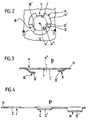
- screw holes in the sealing plates From Screw hole edge 14 'are facing inwards, i. H. in the direction on a hole center 14 '', three holding tongues I, II and III, which are arranged at equal angular distances from each other are and are formed from the sheet of the sealing plate 12.
- Inner edge regions of the holding tongues facing the hole center 14 ′′ I to III were designated I ', II' and III '; the Edges of these inner edge regions facing the hole center 14 ′′ are also circular arcs and define a circular core hole concentric to the hole center 14 '' 14 '' ', the diameter of which is only slightly larger than the core diameter of the thread of the cap screw to be held.
- Each of the tabs II and III is both in the area of their Root as well as at the radially outer end of its inner edge area II 'and III' each bent at an obtuse angle so that a cross-section in the form of a somewhat flat Z results.
- the inner edge regions II 'and III' run parallel to the plane of the sealing plate 12, but in such a way different distances from the actual sealing plate (measured in the direction of arrow S) that the inner Edge areas I ', II' and III '(taking into account their angular distances from each other) corresponding to the pitch of the screw thread in the direction of arrow S offset from each other are.
- the width measured in the circumferential direction of the screw hole 14 the retaining tongues I to III was taking into account the Sheet thickness of the sealing plate 12 chosen so that the inner Edge areas I ', II' and III 'so in the thread or the threads of the screw to be held can intervene, that at least no significant deformation of the retaining tongues I to III occurs.
Abstract
Description
Die Erfindung betrifft eine Dichtung, insbesondere eine Dichtung für eine Kraftfahrzeugkomponente, welche mindestens eine Blechlage aufweist, die wenigstens ein Schraubenloch für den Durchtritt des Gewindeschafts einer Schraube besitzt.The invention relates to a seal, in particular a seal for a motor vehicle component which has at least one Has sheet metal layer, the at least one screw hole for the Passage of the threaded shaft of a screw.
Fahrzeughersteller verlangen in immer größerem Umfang von ihren Zulieferern, daß letztere Bauteile samt zugehörigen Komponenten in vormontiertem Zustand anliefern; aber selbst wenn ein Zulieferer ein Bauteil ohne zugehörige Komponenten liefert, werden die letzteren im Werk des Fahrzeugherstellers oft schon am Bauteil angebracht, ehe dieses zur Montage an das Montageband gebracht wird.Vehicle manufacturers are demanding more and more their suppliers that the latter components including associated Deliver components in pre-assembled condition; but yourself if a supplier has a component without associated components supplies, the latter are in the vehicle manufacturer's factory often already attached to the component before it is installed the assembly line is brought.
Zu einer Dichtung, insbesondere zu Flachdichtungen, gehören üblicherweise Montageschrauben, und im Zuge der vorstehend beschriebenen Bestrebungen wird gefordert, daß die Dichtung samt Montageschrauben an das Montageband angeliefert wird, wobei die Schrauben verliersicher an der Dichtung gehalten werden sollen.Belong to a seal, especially flat seals usually mounting screws, and in the course of the above Desired efforts are required that the seal is delivered to the assembly line with assembly screws, the screws being held captive on the seal should be.
Verliersicherungen für Schrauben sind in vielfältiger Ausbildung bekannt; so zeigt z. B. das DE-U-87 08 965 eine Kopfschraube mit einer aus einem elastischen Kunststoff hergestellten Unterlage, welche ein Schraubenloch für den Durchtritt des Gewindeschafts der Kopfschraube sowie eine Verliersicherung für die Kopfschraube aufweist, um letztere an der Unterlage zu halten. An den Rand des Schraubenlochs der Kunststoff-Unterlage sind vier Haltezungen einstückig angeformt, welche vor dem Einstecken der Kopfschraube in das Schraubenloch der Unterlage alle in einer den Haltezungen gemeinsamen Ebene liegen, und die Kopfschraube hat zwischen ihrem Kopf und ihrem Gewindeschaft eine Ringnut, in die die Haltezungen eingreifen, nachdem der Gewindeschaft unter elastischer Auslenkung der Haltezungen durch das Schraubenloch der Unterlage hindurchgeschoben wurde.Loss protection devices for screws are in various forms known; so shows z. B. DE-U-87 08 965 a head screw with one made from an elastic plastic Pad which has a screw hole for the passage of the threaded shaft of the cap screw and a captive lock for the cap screw to the latter on the Hold document. To the edge of the screw hole Plastic support is four integral tongues formed, which before inserting the cap screw into the Screw hole of the pad all in a common to the retaining tongues Level, and the cap screw has between an annular groove in its head and its threaded shaft, into which the Retain tabs engage after the threaded shaft is under elastic deflection of the retaining tongues through the screw hole the pad was pushed through.
Moderne Dichtungen für Kraftfahrzeuge haben häufig eine metallische Dichtungsplatte aus einer oder mehreren Blechlagen, welche gegebenenfalls vollflächig oder partiell mit einem meist elastomeren Beschichtungsmaterial beschichtet sind, und der Erfindung lag die Aufgabe zugrunde, für eine Dichtung mit mindestens einer Blechlage eine Verliersicherung für Schrauben zu schaffen, wobei sich die Verliersicherung einfach herstellen lassen und nicht zu Komplikationen bei der Montage führen soll.Modern seals for motor vehicles often have one metallic sealing plate made of one or more layers of sheet metal, which, if necessary, over the entire surface or partially a mostly elastomeric coating material are, and the invention was based on the task Seal with at least one sheet layer is a captive device to create for screws, being the captive easy to manufacture and not to complications Assembly should lead.
Ausgehend von einer Dichtung mit mindestens einer Blechlage, welche wenigstens ein Schraubenloch für den Durchtritt des Gewindeschafts einer Schraube aufweist, läßt sich diese Aufgabe erfindungsgemäß dadurch lösen, daß vom Rand des Schraubenlochs mehrere mit der Blechlage einstückige Haltezungen abstehen, welche über den Lochumfang verteilt und im Abstand voneinander angeordnet sind, daß die dem Lochzentrum zugewandten Randbereiche der Haltezungen - in Achsrichtung des Schraubenlochs gesehen - ein kreisförmiges Kernloch definieren, dessen Durchmesser dem Kerndurchmesser des Schraubengewindes entspricht, daß die Breite der Haltezungen sowie die Dicke der Blechlage mindestens in den dem Lochzentrum zugewandten Randbereichen der Haltezungen deren Eingriff in das Schraubengewinde ermöglicht, und daß mindestens ein Teil der Haltezungen derart aus der Ebene der Blechlage herausgebogen ist, daß die dem Lochzentrum zugewandten Randbereiche der Haltezungen der Steigung des Schraubengewindes entsprechend in Achsrichtung des Schraubenlochs gegeneinander versetzt angeordnet sind.Starting from a seal with at least one sheet layer, which has at least one screw hole for the passage of the Has threaded shaft of a screw, this task can be done solve according to the invention that from the edge of the screw hole several holding tongues in one piece with the sheet metal layer protrude, which is distributed over the circumference of the hole and at a distance are arranged from each other that the hole center facing Edge areas of the holding tongues - in the axial direction of the Seen screw hole - define a circular core hole, the diameter of which corresponds to the core diameter of the screw thread corresponds to the width of the retaining tongues as well as the Thickness of the sheet metal layer at least in the hole center Edge areas of the retaining tongues their engagement in the Allows screw threads, and that at least part of the Retaining tongues bent out of the plane of the sheet metal layer in this way is that the edge areas facing the hole center of the Retaining tongues corresponding to the pitch of the screw thread offset from each other in the axial direction of the screw hole are arranged.
Derart gestaltete Haltezungen lassen sich mit einem Stanz-Biege-Werkzeug bei der Herstellung des Schraubenlochs, gegebenenfalls sogar im Zuge des Ausstanzens der Blechlage bei gleichzeitiger Herstellung des Schraubenlochs, sowohl ausstanzen als auch biegen, wobei das Werkzeug ohne weiteres so gestaltet werden kann, daß die Blechlage nach der Durchführung des Stanz-Biege-Vorgangs von selbst aus dem Werkzeug herausfällt. Hat die Blechlage von Hause aus eine Blechstärke, welche es nicht erlauben würde, daß die Haltezungen in das Schraubengewinde eingreifen, kann mit dem Werkzeug die Blechstärke der dem Lochzentrum zugewandten Randbereiche der Haltezungen auch ohne weiteres durch Prägen so verringert werden, daß diese Randbereiche dann in das Schraubengewinde eingreifen können. Im Gegensatz zu einer Verliersicherung, bei der alle Haltezungen bzw. deren dem Lochzentrum zugewandten Randbereiche alle in ein und derselben Ebene liegen, so daß ohne eine Verformung der Haltezungen beim Einbringen der Schraube in das Schraubenloch nur eine der Haltezungen in das Schraubengewinde eingreifen kann, ermöglicht es die erfindungsgemäße Verliersicherung, daß alle Haltezungen in das Schraubengewinde eingreifen können, dadurch die Schraube wirklich verliersicher an der Dichtung gehalten wird, und zwar mit einem Verlauf der Schraubenachse senkrecht zur Ebene der Blechlage, und daß sich die Schraube im Schraubenloch zentriert - dies stellt für die spätere Montage einen ganz erheblichen Vorteil dar. Außerdem führt die erfindungsgemäße Verliersicherung noch zu den folgenden weiteren Vorteilen: Wird die Schraube während des Einbringens in die Dichtung gedreht, ist keinerlei Kraftaufwand erforderlich; die elastisch auslenkbaren Haltezungen lassen es aber auch zu, daß die Schraube, ohne sie zu drehen, einfach in das Schraubenloch eingesteckt wird, während ein Zurückschieben der Schraube nicht oder nur mit einem relativ hohen Kraftaufwand möglich ist.Such holding tongues can be designed with a punching and bending tool in the manufacture of the screw hole, if necessary even in the course of punching out the sheet metal layer simultaneous production of the screw hole, both punch out bend as well, the tool being so can be designed that the sheet metal layer after the implementation the punching and bending process itself from the tool falls out. The sheet metal layer has one by default Sheet thickness, which would not allow the retaining tongues can engage in the screw thread with the tool the sheet thickness of the edge areas facing the hole center the retaining tongues easily by embossing like this be reduced that these edge areas then in the screw thread can intervene. Unlike a loss protection, in which all holding tongues or their the hole center facing edge areas all in one and the same plane lie so that without deformation of the retaining tongues when inserting the screw into the screw hole only one of the retaining tabs can engage in the screw thread makes it possible the captive device according to the invention that all retaining tongues can engage in the screw thread, thereby the Screw really held captive on the seal becomes, with a course of the screw axis perpendicular to the level of the sheet metal layer, and that the screw is in the screw hole centered - this provides one for later assembly very significant advantage. In addition, the invention Loss prevention against the following further advantages: If the screw is inserted into the Twisted seal, no effort is required; the elastically deflectable holding tongues also leave it there to the screw without turning it into the Screw hole is inserted while pushing back the screw or only with a relatively high effort is possible.
Grundsätzlich wäre es möglich, die aus der Ebene der Blechlage herauszubiegende Haltezunge bzw. die herauszubiegenden Haltezungen so zu biegen, daß sie schräg zur Ebene der Blechlage verläuft bzw. verlaufen. Bevorzugt werden jedoch Ausführungsformen, bei denen jede aus der Ebene der Blechlage herausgebogene Haltezunge sowohl im Bereich ihrer Wurzel als auch nahe ihrem dem Lochzentrum zugewandten Randbereich derart abgewinkelt ist, daß der letztere mindestens ungefähr parallel zur Ebene der Blechlage verläuft, denn dann stehen die zentrumsnahen Randbereiche aller Haltezungen senkrecht im Schraubengewinde.Basically, it would be possible from the level of Retaining tab or sheet to be bent out Bend the tongues so that they are at an angle to the plane of the Sheet metal layer runs or run. However, are preferred Embodiments, each from the plane of the sheet metal layer bent out tongue both in the area of its root and also near their edge area facing the hole center is angled that the latter is at least approximately runs parallel to the level of the sheet metal layer, because then stand the edge areas of all holding tongues near the center perpendicular in Screw thread.
Von besonders einfacher Gestaltung wird die erfindungsgemäße Verliersicherung dann, wenn eine der Haltezungen eben ist und in der Ebene der Blechlage liegt, da dann nur die zweite bzw. alle anderen Haltezungen aus der Blechlage herausgebogen werden muß bzw. müssen.The inventive design is particularly simple Loss prevention when one of the retaining tongues is level and lies in the plane of the sheet metal layer, since then only the second or all other retaining tabs are bent out of the sheet metal layer must or must.
Eine besonders wirksame Verliersicherung und eine besonders gute Zentrierung der Schraube ergibt sich dann, wenn die dem Lochzentrum zugewandten Randbereiche der Haltezungen eine dem Kernloch entsprechende kreisbogenförmige Kontur aufweisen, obwohl natürlich auch Ausführungsformen denkbar sind, bei denen die dem Lochzentrum zugewandten Randbereiche der Haltezungen z. B. eine dreiecksförmige oder konvex halbkreisförmige Kontur besitzen. A particularly effective protection against loss and a special one The screw is well centered when the Edge areas of the retaining tongues facing the center of the hole Have a corresponding circular arc-shaped contour, although of course embodiments are also conceivable for which the edge areas of the holding tongues facing the hole center e.g. B. a triangular or convex semicircular Have a contour.
Damit die Haltezungen gut in das Schraubengewinde eingreifen können, ohne daß sie beim Einbringen der Schraube in das Schraubenloch verformt werden müssen, sollten die dem Lochzentrum zugewandten Randbereiche der Haltezungen verhältnismäßig schmal sein, weshalb im Hinblick auf die erwünschte Zentrierung der Schraube im Schraubenloch Ausführungsformen mit mehr als zwei Haltezungen bevorzugt werden, insbesondere Ausführungsformen mit drei in gleichen Winkelabständen voneinander angeordneten Haltezungen.So that the retaining tongues engage well in the screw thread can without them when inserting the screw into the Screw hole must be deformed, the hole center facing edge areas of the retaining tongues proportionately be narrow, which is why in terms of the desired Centering the screw in the screw hole embodiments with more than two retaining tongues are preferred, in particular Embodiments with three at equal angular distances from each other arranged holding tongues.
Schließlich wird empfohlen, die erfindungsgemäße Verliersicherung so zu gestalten, daß die aus der Ebene der Blechlage herausgebogene bzw. herausgebogenen Haltezunge bzw. Haltezungen in Montagerichtung der Schraube von der Blechlage absteht bzw. abstehen, da dann kein allzu hoher Kraftaufwand erforderlich ist, um die Schraube, ohne sie zu drehen, in das Schraubenloch einstecken zu können, und zwar in der Richtung, in der die Haltezungen aus der Blechlage herausgebogen wurden.Finally, it is recommended to secure against loss in accordance with the invention in such a way that those from the level of Sheet metal layer bent out or bent out retaining tongue or Retaining tongues in the mounting direction of the screw from the sheet metal layer protrudes or protrude, since then not too much effort is required to turn the screw into it without turning it To be able to insert the screw hole in the direction in which the retaining tongues were bent out of the sheet metal layer.
Weitere Merkmale, Vorteile und Einzelheiten der Erfindung ergeben sich aus der beigefügten zeichnerischen Darstellung und der nachfolgenden Beschreibung einer besonders vorteilhaften Ausführungsform der erfindungsgemäßen Verliersicherung einer Dichtung; in der Zeichnung zeigen:
- Fig. 1
- eine Draufsicht auf einen Teil einer erfindungsgemäßen Dichtung mit mehreren Schraubenlöchern, von denen drei mit einer erfindungsgemäßen Verliersicherung versehen sind;
- Fig. 2
- den Ausschnitt A aus Fig. 1 in größerem Maßstab;
- Fig. 3
- einen Schnitt nach der Linie 3-3 in Fig. 2 und
- Fig. 4
- die Abwicklung des in Fig. 3 dargestellten Schnitts.
- Fig. 1
- a plan view of part of a seal according to the invention with a plurality of screw holes, three of which are provided with a captive device according to the invention;
- Fig. 2
- the section A of Figure 1 on a larger scale.
- Fig. 3
- a section along the line 3-3 in Fig. 2 and
- Fig. 4
- the processing of the section shown in Fig. 3.
Die Fig. 1 zeigt einen Teil einer Dichtung 10, deren Dichtungsplatte
12 von einer einzigen Blechlage gebildet wird,
welche ein- oder beidseitig vollflächig oder partiell mit
einer insbesondere elastomeren Dichtungsmasse beschichtet
sein kann.Fig. 1 shows part of a
In dem in Fig. 1 dargestellten Teil der Dichtung 10 besitzt
die Dichtungsplatte 12 drei mit erfindungsgemäßen Verliersicherungen
versehene Schraubenlöcher 14, 16, 18 für den
Durchtritt der Gewindeschäfte von nicht dargestellten Kopfschrauben.In the part of the
Die Schraubenlöcher können alle identisch ausgebildet sein,
und anhand der Figuren 2 bis 4 soll nun die Gestaltung der am
Schraubenloch 14 vorgesehenen Verliersicherung näher beschrieben
werden.The screw holes can all be identical,
and based on Figures 2 to 4, the design of the
Das Schraubenloch 14 hat einen von mehreren Kreisbogensegmenten
gebildeten Rand 14', welcher einen Kreis mit einem Durchmesser
definiert, der gleich dem Durchmesser herkömmlich gestalteter
Schraubenlöcher in Dichtungsplatten ist. Vom
Schraubenlochrand 14' stehen nach innen, d. h. in Richtung
auf ein Lochzentrum 14'', drei Haltezungen I, II und III ab,
welche in gleichen Winkelabständen voneinander angeordnet
sind und vom Blech der Dichtungsplatte 12 gebildet werden.
Dem Lochzentrum 14'' zugewandte innere Randbereiche der Haltezungen
I bis III wurden mit I', II' und III' bezeichnet; die
dem Lochzentrum 14'' zugewandten Kanten dieser inneren Randbereiche
sind gleichfalls kreisbogenförmig und definieren ein
kreisförmiges, zum Lochzentrum 14'' konzentrisches Kernloch
14''', dessen Durchmesser nur ganz geringfügig größer ist als
der Kerndurchmesser des Gewindes der zu haltenden Kopfschraube.The
Wie die Figuren 3 und 4 erkennen lassen, ist die Haltezunge I
eben und liegt in der Ebene der Dichtungsplatte, wohingegen
die Haltezungen II und III aus der Dichtungsplattenebene
herausgebogen wurden, und zwar in Richtung des in Fig. 3 eingezeichneten
Pfeils S, der auch die Richtung angibt, in der
die zu haltende Kopfschraube in das Schraubenloch 14 einzustecken
ist.As can be seen in FIGS. 3 and 4, the retaining tongue I
flat and lies in the plane of the sealing plate, whereas
the retaining tongues II and III from the sealing plate level
were bent out, in the direction of that shown in Fig. 3
Arrow S, which also indicates the direction in which
insert the cap screw to be held into the
Jede der Haltezungen II und III ist sowohl im Bereich ihrer
Wurzel als auch am radial äußeren Ende ihres inneren Randbereichs
II' bzw. III' jeweils stumpfwinklig so abgebogen, daß
sich ein Querschnitt in Gestalt eines etwas flachgezogenen Z
ergibt. Die inneren Randbereiche II' und III' verlaufen
parallel zur Ebene der Dichtungsplatte 12, jedoch in derart
unterschiedlichen Abständen von der eigentlichen Dichtungsplatte
(in Richtung des Pfeils S gemessen), daß die inneren
Randbereiche I', II' und III' (unter Beachtung ihrer Winkelabstände
voneinander) der Steigung des Schraubengewindes entsprechend
in Richtung des Pfeils S gegeneinander versetzt angeordnet
sind.Each of the tabs II and III is both in the area of their
Root as well as at the radially outer end of its inner edge area
II 'and III' each bent at an obtuse angle so that
a cross-section in the form of a somewhat flat Z
results. The inner edge regions II 'and III' run
parallel to the plane of the
Die in Umfangsrichtung des Schraubenlochs 14 gemessene Breite
der Haltezungen I bis III wurde unter Berücksichtigung der
Blechstärke der Dichtungsplatte 12 so gewählt, daß die inneren
Randbereiche I', II' und III' so in den Gewindegang bzw.
die Gewindegänge der zu haltenden Schraube eingreifen können,
daß dabei zumindest keine nennenswerte Verformung der Haltezungen
I bis III eintritt.The width measured in the circumferential direction of the
Wird eine Schraube in Richtung des Pfeils S in das Schraubenloch
14 eingeführt und dabei nicht gedreht, werden die Haltezungen
I, II und III in Richtung des Pfeils S elastisch ausgelenkt
und springen dann in den Gewindegang bzw. in die Gewindegänge
zurück. Da die Haltezungen II und III schräg von
der eigentlichen Dichtungsplatte 12 abstehen und beide in
Richtung des Pfeils S aus der Ebene der Dichtungsplatte herausgebogen
wurden, läßt sich die Schraube jedoch aus dem
Schraubenloch 14 nicht mehr oder nur unter großem Kraftaufwand
herausziehen bzw. entgegen dem Pfeil S zurückdrücken.Insert a screw in the direction of arrow S into the
Vor allem dann, wenn die Haltezungen I, II, III so gestaltet
sind, daß sie nicht nur über einen sehr kleinen Umfangswinkel
in das Schraubengewinde eingreifen, kann eine Abwandlung der
zeichnerisch dargestellten Ausführungsform der erfindungsgemäßen
Verliersicherung empfehlenswert sein; bei dieser Abwandlung
verlaufen die dem Lochzentrum 14'' zugewandten Randbereiche
I', II' und III' der Haltezungen nicht parallel zur
Ebene der Blechlage 12, wie dies in den Figuren 3 und 4 dargestellt
ist, sondern sind gegen diese Ebene der Steigung des
Schraubengewindes entsprechend geneigt. Dadurch kann vermieden
werden, daß die erfindungsgemäße Verliersicherung beim
Montieren der Dichtung, d. h. beim Anziehen der Schrauben, zu
einer Erhöhung des hierfür erforderlichen Drehmoments führt,
weil sich die in das Schraubengewinde eingreifenden Haltezungen
an die Flanken des Gewindes anschmiegen. Außerdem
lassen sich Haltezungen mit derart geneigt verlaufenden Randbereichen
gleichfalls ohne weiteres mittels eines Stanz-Biege-Werkzeugs
herstellen.Especially when the retaining tongues I, II, III are designed in this way
are that they don't just have a very small circumferential angle
engage in the screw thread, a modification of the
illustrated embodiment of the invention
Loss prevention should be recommended; with this variation
run the edge areas facing the hole center 14 ''
I ', II' and III 'of the retaining tongues are not parallel to
Level of the
Claims (8)
Applications Claiming Priority (2)
| Application Number | Priority Date | Filing Date | Title |
|---|---|---|---|
| DE29809130U | 1998-05-20 | ||
| DE29809130U DE29809130U1 (en) | 1998-05-20 | 1998-05-20 | Seal, in particular for motor vehicles |
Publications (3)
| Publication Number | Publication Date |
|---|---|
| EP0959273A2 true EP0959273A2 (en) | 1999-11-24 |
| EP0959273A3 EP0959273A3 (en) | 1999-12-01 |
| EP0959273B1 EP0959273B1 (en) | 2003-09-03 |
Family
ID=8057461
Family Applications (1)
| Application Number | Title | Priority Date | Filing Date |
|---|---|---|---|
| EP99106295A Expired - Lifetime EP0959273B1 (en) | 1998-05-20 | 1999-04-16 | Gasket, in particular for motor vehicle |
Country Status (6)
| Country | Link |
|---|---|
| US (1) | US6371492B1 (en) |
| EP (1) | EP0959273B1 (en) |
| JP (1) | JP3188881B2 (en) |
| BR (1) | BR9902092A (en) |
| DE (2) | DE29809130U1 (en) |
| ES (1) | ES2202949T3 (en) |
Cited By (1)
| Publication number | Priority date | Publication date | Assignee | Title |
|---|---|---|---|---|
| WO2004085891A1 (en) * | 2003-03-27 | 2004-10-07 | Federal-Mogul Sealing Systems Bretten Gmbh | Dimensionally stable elastomer seal |
Families Citing this family (9)
| Publication number | Priority date | Publication date | Assignee | Title |
|---|---|---|---|---|
| DE19932727C1 (en) * | 1999-07-14 | 2000-11-30 | Elringklinger Gmbh | Flat seal for automobile component e.g. cylinder head gasket, has fixing screw opening in sheet metal layer of seal provided with screw retaining elements by bending sections of opening edge |
| DE10107939B4 (en) * | 2001-02-20 | 2012-06-14 | Pierburg Gmbh | gasket |
| JP3762250B2 (en) * | 2001-05-15 | 2006-04-05 | トヨタ自動車株式会社 | Metal gasket |
| US6533287B1 (en) * | 2001-11-21 | 2003-03-18 | Dana Corporation | Bolt retention mechanism for MLS gasket |
| US6926286B2 (en) | 2002-03-28 | 2005-08-09 | Nichias Corporation | Gasket holding device |
| US20070216109A1 (en) * | 2006-03-16 | 2007-09-20 | Elringklinger Ag | Turbocharger gasket |
| DE102012215872A1 (en) * | 2012-09-07 | 2014-03-13 | Rohde & Schwarz Gmbh & Co. Kg | Failover element for assembly of captive screw at cable shoe for fastening electric conductors at electric contact, has disk-shaped holding element for retaining head of screw, and tongue radial outwardly extending at holding element |
| CN105026705B (en) * | 2013-02-25 | 2018-01-02 | 夏伊洛工业公司 | Modular assembly with press-in cooperation fastener hole |
| US9055983B1 (en) * | 2014-04-24 | 2015-06-16 | Amendia, Inc. | Self-locking bone screw receiver |
Citations (1)
| Publication number | Priority date | Publication date | Assignee | Title |
|---|---|---|---|---|
| DE8708965U1 (en) | 1987-06-29 | 1988-10-27 | Robert Bosch Gmbh, 7000 Stuttgart, De |
Family Cites Families (7)
| Publication number | Priority date | Publication date | Assignee | Title |
|---|---|---|---|---|
| US2117775A (en) * | 1936-12-03 | 1938-05-17 | Albert H Tinnerman | Fastening device |
| US2221498A (en) * | 1937-10-04 | 1940-11-12 | Tinnerman Products Inc | Sheet metal fastening means |
| US4784396A (en) * | 1987-06-01 | 1988-11-15 | Ford Motor Company | Retaining clip and gasket for engine subassembly |
| US5544902A (en) * | 1994-06-30 | 1996-08-13 | Dana Corporation | Metal gasket with bolt retention freature |
| US5513855A (en) * | 1994-07-05 | 1996-05-07 | Ishikawa Gasket Co., Ltd. | Metal laminate gasket with engaging device having curved edges |
| JP3666827B2 (en) * | 1995-10-27 | 2005-06-29 | 株式会社青山製作所 | Screw tightening clip |
| US5673920A (en) * | 1996-09-16 | 1997-10-07 | Fel-Pro Incorporated | Gasket bolt hole with retaining beam and slot |
-
1998
- 1998-05-20 DE DE29809130U patent/DE29809130U1/en not_active Expired - Lifetime
-
1999
- 1999-04-16 EP EP99106295A patent/EP0959273B1/en not_active Expired - Lifetime
- 1999-04-16 DE DE59906824T patent/DE59906824D1/en not_active Expired - Fee Related
- 1999-04-16 ES ES99106295T patent/ES2202949T3/en not_active Expired - Lifetime
- 1999-05-18 US US09/313,887 patent/US6371492B1/en not_active Expired - Fee Related
- 1999-05-19 BR BR9902092-0A patent/BR9902092A/en not_active IP Right Cessation
- 1999-05-20 JP JP14014699A patent/JP3188881B2/en not_active Expired - Fee Related
Patent Citations (1)
| Publication number | Priority date | Publication date | Assignee | Title |
|---|---|---|---|---|
| DE8708965U1 (en) | 1987-06-29 | 1988-10-27 | Robert Bosch Gmbh, 7000 Stuttgart, De |
Cited By (1)
| Publication number | Priority date | Publication date | Assignee | Title |
|---|---|---|---|---|
| WO2004085891A1 (en) * | 2003-03-27 | 2004-10-07 | Federal-Mogul Sealing Systems Bretten Gmbh | Dimensionally stable elastomer seal |
Also Published As
| Publication number | Publication date |
|---|---|
| US6371492B1 (en) | 2002-04-16 |
| ES2202949T3 (en) | 2004-04-01 |
| DE59906824D1 (en) | 2003-10-09 |
| EP0959273B1 (en) | 2003-09-03 |
| JP2000027996A (en) | 2000-01-25 |
| JP3188881B2 (en) | 2001-07-16 |
| DE29809130U1 (en) | 1998-09-03 |
| BR9902092A (en) | 2000-01-11 |
| EP0959273A3 (en) | 1999-12-01 |
Similar Documents
| Publication | Publication Date | Title |
|---|---|---|
| EP2594813B1 (en) | Blind rivet element | |
| EP0959273B1 (en) | Gasket, in particular for motor vehicle | |
| DE10220233A1 (en) | Mother and process for its manufacture | |
| EP1181460B1 (en) | Connecting device | |
| WO2019091945A1 (en) | Securing means for screws, and mounting unit | |
| DE102014009410B4 (en) | A method for connecting a Einpressbolzens with a pre-hole having sheet metal part and cover for performing the method | |
| EP3433515B1 (en) | Sealing arrangement and method for producing a sealing arrangement | |
| DE102013110429A1 (en) | Plastic fastener and mounting arrangement hereby | |
| EP1503096B1 (en) | Retaining member for securing at least one bearing | |
| DE102021213541B3 (en) | gear | |
| DE102008020099B4 (en) | By at least one fastening screw to be mounted component | |
| DE2220657A1 (en) | ARRANGEMENT FOR FASTENING TWO COMPONENTS | |
| DE102011106989A1 (en) | Fastening element and method for producing a fastening arrangement | |
| DE4313845C1 (en) | Locknut for threaded fasteners - has ring disc with alternating recesses and claws, which lock into ring groove | |
| EP3956572B1 (en) | Connection unit and method for producing a connection unit | |
| EP2143961B1 (en) | Bore sealing arrangement | |
| DE102017223636A1 (en) | Assembly unit and fixing sleeve for such a mounting unit | |
| EP3974680A1 (en) | Multi-component wheel, toothed wheel and planetary gear | |
| DE10117851C2 (en) | connecting device | |
| DE19932727C1 (en) | Flat seal for automobile component e.g. cylinder head gasket, has fixing screw opening in sheet metal layer of seal provided with screw retaining elements by bending sections of opening edge | |
| WO2018233874A1 (en) | Coupling comprising a shaft inserted at least partially into a hollow shaft and a ring slipped onto the hollow shaft, and planetary gearset | |
| DE3329967A1 (en) | Screwed or riveted connection | |
| EP0930439A1 (en) | Fastening of at least two superposed sheets by means of a self-tapping screw | |
| EP1380761B1 (en) | Fastening element for a wall opening, in particular of a vehicle body | |
| EP3323584A1 (en) | Method for manufacturing an injection-moulded part and injection moulded part |
Legal Events
| Date | Code | Title | Description |
|---|---|---|---|
| PUAI | Public reference made under article 153(3) epc to a published international application that has entered the european phase |
Free format text: ORIGINAL CODE: 0009012 |
|
| PUAL | Search report despatched |
Free format text: ORIGINAL CODE: 0009013 |
|
| AK | Designated contracting states |
Kind code of ref document: A2 Designated state(s): DE ES FR GB IT |
|
| AX | Request for extension of the european patent |
Free format text: AL;LT;LV;MK;RO;SI |
|
| AK | Designated contracting states |
Kind code of ref document: A3 Designated state(s): AT BE CH CY DE DK ES FI FR GB GR IE IT LI LU MC NL PT SE |
|
| AX | Request for extension of the european patent |
Free format text: AL;LT;LV;MK;RO;SI |
|
| RIC1 | Information provided on ipc code assigned before grant |
Free format text: 6F 16J 15/08 A |
|
| 17P | Request for examination filed |
Effective date: 19991106 |
|
| AKX | Designation fees paid |
Free format text: DE ES FR GB IT |
|
| RAP1 | Party data changed (applicant data changed or rights of an application transferred) |
Owner name: ELRINGKLINGER AG |
|
| RAP1 | Party data changed (applicant data changed or rights of an application transferred) |
Owner name: ELRINGKLINGER AG |
|
| GRAH | Despatch of communication of intention to grant a patent |
Free format text: ORIGINAL CODE: EPIDOS IGRA |
|
| GRAS | Grant fee paid |
Free format text: ORIGINAL CODE: EPIDOSNIGR3 |
|
| GRAA | (expected) grant |
Free format text: ORIGINAL CODE: 0009210 |
|
| AK | Designated contracting states |
Kind code of ref document: B1 Designated state(s): DE ES FR GB IT |
|
| REG | Reference to a national code |
Ref country code: GB Ref legal event code: FG4D Free format text: NOT ENGLISH |
|
| REF | Corresponds to: |
Ref document number: 59906824 Country of ref document: DE Date of ref document: 20031009 Kind code of ref document: P |
|
| GBT | Gb: translation of ep patent filed (gb section 77(6)(a)/1977) |
Effective date: 20031119 |
|
| REG | Reference to a national code |
Ref country code: ES Ref legal event code: FG2A Ref document number: 2202949 Country of ref document: ES Kind code of ref document: T3 |
|
| ET | Fr: translation filed | ||
| PLBE | No opposition filed within time limit |
Free format text: ORIGINAL CODE: 0009261 |
|
| STAA | Information on the status of an ep patent application or granted ep patent |
Free format text: STATUS: NO OPPOSITION FILED WITHIN TIME LIMIT |
|
| 26N | No opposition filed |
Effective date: 20040604 |
|
| PGFP | Annual fee paid to national office [announced via postgrant information from national office to epo] |
Ref country code: ES Payment date: 20090318 Year of fee payment: 11 |
|
| PGFP | Annual fee paid to national office [announced via postgrant information from national office to epo] |
Ref country code: GB Payment date: 20090303 Year of fee payment: 11 |
|
| PGFP | Annual fee paid to national office [announced via postgrant information from national office to epo] |
Ref country code: IT Payment date: 20090324 Year of fee payment: 11 Ref country code: FR Payment date: 20090416 Year of fee payment: 11 Ref country code: DE Payment date: 20090529 Year of fee payment: 11 |
|
| GBPC | Gb: european patent ceased through non-payment of renewal fee |
Effective date: 20100416 |
|
| REG | Reference to a national code |
Ref country code: FR Ref legal event code: ST Effective date: 20101230 |
|
| PG25 | Lapsed in a contracting state [announced via postgrant information from national office to epo] |
Ref country code: DE Free format text: LAPSE BECAUSE OF NON-PAYMENT OF DUE FEES Effective date: 20101103 |
|
| PG25 | Lapsed in a contracting state [announced via postgrant information from national office to epo] |
Ref country code: IT Free format text: LAPSE BECAUSE OF NON-PAYMENT OF DUE FEES Effective date: 20100416 Ref country code: GB Free format text: LAPSE BECAUSE OF NON-PAYMENT OF DUE FEES Effective date: 20100416 |
|
| REG | Reference to a national code |
Ref country code: ES Ref legal event code: FD2A Effective date: 20110715 |
|
| PG25 | Lapsed in a contracting state [announced via postgrant information from national office to epo] |
Ref country code: ES Free format text: LAPSE BECAUSE OF NON-PAYMENT OF DUE FEES Effective date: 20110705 |
|
| PG25 | Lapsed in a contracting state [announced via postgrant information from national office to epo] |
Ref country code: ES Free format text: LAPSE BECAUSE OF NON-PAYMENT OF DUE FEES Effective date: 20100417 |
|
| PG25 | Lapsed in a contracting state [announced via postgrant information from national office to epo] |
Ref country code: FR Free format text: LAPSE BECAUSE OF NON-PAYMENT OF DUE FEES Effective date: 20100430 |