EP0959254B2 - Radially sealed centrifugal pump - Google Patents
Radially sealed centrifugal pump Download PDFInfo
- Publication number
- EP0959254B2 EP0959254B2 EP98203806A EP98203806A EP0959254B2 EP 0959254 B2 EP0959254 B2 EP 0959254B2 EP 98203806 A EP98203806 A EP 98203806A EP 98203806 A EP98203806 A EP 98203806A EP 0959254 B2 EP0959254 B2 EP 0959254B2
- Authority
- EP
- European Patent Office
- Prior art keywords
- pump
- casing
- centrifugal pump
- impeller
- chamber
- Prior art date
- Legal status (The legal status is an assumption and is not a legal conclusion. Google has not performed a legal analysis and makes no representation as to the accuracy of the status listed.)
- Expired - Lifetime
Links
- 238000007789 sealing Methods 0.000 claims description 24
- 239000012530 fluid Substances 0.000 claims description 8
- 230000001050 lubricating effect Effects 0.000 claims description 6
- 239000000463 material Substances 0.000 claims description 6
- 239000012535 impurity Substances 0.000 claims 1
- 239000007788 liquid Substances 0.000 claims 1
- XLYOFNOQVPJJNP-UHFFFAOYSA-N water Substances O XLYOFNOQVPJJNP-UHFFFAOYSA-N 0.000 description 14
- 239000003921 oil Substances 0.000 description 5
- 238000012423 maintenance Methods 0.000 description 4
- 230000007613 environmental effect Effects 0.000 description 3
- 239000000314 lubricant Substances 0.000 description 3
- 238000004519 manufacturing process Methods 0.000 description 3
- 229910001018 Cast iron Inorganic materials 0.000 description 2
- VYZAMTAEIAYCRO-UHFFFAOYSA-N Chromium Chemical compound [Cr] VYZAMTAEIAYCRO-UHFFFAOYSA-N 0.000 description 2
- 239000003795 chemical substances by application Substances 0.000 description 2
- 229910052804 chromium Inorganic materials 0.000 description 2
- 239000011651 chromium Substances 0.000 description 2
- 239000004519 grease Substances 0.000 description 2
- 238000005461 lubrication Methods 0.000 description 2
- 206010010904 Convulsion Diseases 0.000 description 1
- CWYNVVGOOAEACU-UHFFFAOYSA-N Fe2+ Chemical compound [Fe+2] CWYNVVGOOAEACU-UHFFFAOYSA-N 0.000 description 1
- XEEYBQQBJWHFJM-UHFFFAOYSA-N Iron Chemical group [Fe] XEEYBQQBJWHFJM-UHFFFAOYSA-N 0.000 description 1
- 239000007767 bonding agent Substances 0.000 description 1
- 239000000919 ceramic Substances 0.000 description 1
- 230000006866 deterioration Effects 0.000 description 1
- 238000012986 modification Methods 0.000 description 1
- 230000004048 modification Effects 0.000 description 1
- 239000000843 powder Substances 0.000 description 1
- 238000005096 rolling process Methods 0.000 description 1
- 239000012209 synthetic fiber Substances 0.000 description 1
- 229920002994 synthetic fiber Polymers 0.000 description 1
Images

Classifications
-
- F—MECHANICAL ENGINEERING; LIGHTING; HEATING; WEAPONS; BLASTING
- F04—POSITIVE - DISPLACEMENT MACHINES FOR LIQUIDS; PUMPS FOR LIQUIDS OR ELASTIC FLUIDS
- F04D—NON-POSITIVE-DISPLACEMENT PUMPS
- F04D1/00—Radial-flow pumps, e.g. centrifugal pumps; Helico-centrifugal pumps
- F04D1/006—Radial-flow pumps, e.g. centrifugal pumps; Helico-centrifugal pumps double suction pumps
-
- F—MECHANICAL ENGINEERING; LIGHTING; HEATING; WEAPONS; BLASTING
- F04—POSITIVE - DISPLACEMENT MACHINES FOR LIQUIDS; PUMPS FOR LIQUIDS OR ELASTIC FLUIDS
- F04D—NON-POSITIVE-DISPLACEMENT PUMPS
- F04D29/00—Details, component parts, or accessories
- F04D29/08—Sealings
- F04D29/16—Sealings between pressure and suction sides
- F04D29/165—Sealings between pressure and suction sides especially adapted for liquid pumps
- F04D29/167—Sealings between pressure and suction sides especially adapted for liquid pumps of a centrifugal flow wheel
Definitions
- the present invention refers to a radially sealed centrifugal pump.
- incompressible fluids as for instance water
- the pumps are the machines which perform this function, the pumps, according to the working characteristics, are classified as reciprocating, axial, centrifugal pumps, etc.
- centrifugal pumps belong to the family of the turbomachines; in these pumps, the energy exchange between the machine and the fluid is realised through hydrodynamic forces which are exerted by the blades of the machine against the fluid, since said blades are in relative motion as to said fluid.
- centrifugal pumps have been present on the market since long, said pumps, according to their basic structure, comprise an outer casing, within which an impeller, driven by a shaft connected to a motor, can .rotate. Said pumps have, between the casing and the impeller, suitable sealing rings, which perform their function along the generating lines or portions thereof of the opposed surfaces, which are generally substantially cylindrical and coaxial to said impeller.
- the pump externally to the casing and/or to the fluid chamber, the pump has plain or rolling bearings in order to realise the rotatable connection of the shaft, whereon the impeller is splined, to said casing.
- Said pumps have auxiliary circuits and tanks, which are associated to the bearings, in order to contain and to distribute the lubricating grease or oil of the bearings.
- the machine operation presents often high environmental risks since it is noisy and polluting, because of the presence of the auxiliary circuits for, the bearing lubrication and of the production of exhausted lubricating greases and oils.
- the environment is contaminated by a highly polluting agent; further, the lubricant discharged from a machine, for instance when said lubricant is changed, has to be stored and disposed of in the proper manner.
- DE 142 214 C relates to a centrifugal pump according to the preamble of claim 1.
- a purpose of the present invention is to eliminate the disadvantages of the known art, through the realisation of a centrifugal pump which achieves high levels of efficiency.
- Another purpose of the invention is to realise a centrifugal pump which has extremely reduced axial dimensions and, as a consequence, extremely reduced weight.
- a further purpose of the invention is to realise a pump without auxiliary lubricating apparatuses and without oil or grease tanks.
- Last but not least purpose of the invention is to realise an inexpensive and reliable pump.
- the pump has sealing rings which have smaller dimensions in comparison with the known art and which are reusable if said rings are made, for instance, of chromium plated cast iron.
- the pump has pairs of same size rings, associated with the casing and/or with the impeller, said rings are suitable to stand an axial force, they do not pose any ovalization problem and they strongly reduce the thermal expansion and the shaft deflection problems, especially when the shaft has a certain significant length between the supports.
- the pump manufacturing is simplified since the surfaces to be machined, between which the sealing is realised, are flat; the assembly is simplified because the centering is extremely easy and the use and the maintenance are very simple and inexpensive since there is no possibility of seizures and because of the increased easiness to coat and treat flat surfaces.
- the pump has a very low environmental impact since it does not discharge the very polluting exhausted greases or oils which have to be disposed of in a proper manner.
- centrifugal pump indicated by numeral 1
- a shaft 4 on which an impeller 5 is splined, is rotatably connected within a casing 2.
- the casing 2 and the impeller 5 have opposed surfaces 21, 22 perpendicular to the impeller axis, and seal and protection means 6 are placed between said surfaces in order to avoid water leakage from the high pressure chamber to the low pressure chamber and in order to protect the surfaces of the pump main components.
- Said means 6 comprises a sealing ring which is detachably connected to the casing 2 through locking means 7, as for instance rivets, other mechanical devices and/or bonding agents, or, as in the example, screws.
- the impeller 5, during operation transmits centrifugal forces to the water, said forces enhance the sealing efficiency since they move the water away from the axis of the impeller 5.
- the ring 6 allows the automatic centering of the impeller 5 within the casing 2 without the need of providing proper axial locking elements.
- the ring 6 can transmit axial forces to the casing 2 and the impeller 5, said forces maintain, in a natural and autonomous way, the impeller 5 in its correct position inside the casing 2.
- the pump has the sealing ring 6 detachably connected to the impeller 5 ( Figure 4) by means of screws 7; a further embodiment of the pump according to the invention has a couple of sealing rings 6 so that a first ring is connected to the impeller 5 and a second ring is connected to the casing 2 ( Figure 5).
- the rings 6 are made of wearing materials with a low friction coefficient in order to have a wearing element which will be changed when the material deterioration is such that it does not guarantee the pump proper operation any more.
- Said rings are preferably made of synthetic fibers, ceramic materails, sintered powders, ferrous materials coated with suitable materials, for instance chromium plated cast iron rings.
- the shaft 4 is rotatably connected to the casing 2 by means of two plain bearings 23, 24 which are positioned in a first and a second cylindrical housing 8, 9 of the casing 2. At the ends of the housings 8, 9 the casing has a ledge 18 to allow the detachable connection of a cover 10 or of sealing means 12.
- the cover 10 closes said housing 8 and forms a first chamber 11 suitable to contain water. Further, the cover 10 can have an opening to connect said chamber 11 with the outside environment, said opening being closed by means of a threaded cap 17.
- a hydraulic connection device 16 connects chamber 11 with a high pressure chamber 20, so as to allow the passage of the water from chamber 20 to chamber 11, this will allow the lubrication of the plain bearing 23, since said chamber 11 is in communication with said bearing.
- the housing 9, wherein the second plain bearing 24 is positioned, has its front portion closed by the sealing means 12, which allows the shaft 4 to project from the pump casing 2 and to be connected to a drive machine not shown in the figures.
- the sealing means 12 define, at the end of the housing 9 of the bearing 24, a chamber 14 which faces the bearing 24, said chamber is connected to the high pressure chamber 20 through a hydraulic connection device 16 and through the sealing means 12. Therefore, the water coming from the high pressure chamber 20 lubricates both the bearing 23 positioned in the housing 8 and the bearing 24 positioned in the housing 9.
- a further embodiment of the pump according to the invention has sealing rings 6 positioned between the casing 2 and the impeller 5, said rings exert, according to the invention, their sealing action along radial surfaces, and ball bearings 30 which support the shaft 44 ( Figure 6).
- Another embodiment of the pump according to the invention has sealing rings which exert their sealing action along radial surfaces, and roller bearings which support the shaft and rotatably connect said shaft to the casing.
- the pump operation is as follows.
- the pump inlet water is sent into a low pressure chamber 19 by the impeller 5 which gives up energyto the water, puts said water under high pressure and discharges it into a high pressure chamber 20.
- the seal between the chambers 19, 20 is guaranteed by the sealing rings 6, which, since they are detachably connected to the casing 2, move in relation to the impeller 5. Said rings obstruct very efficiently the passage of the water from the high pressure chamber to the low pressure chamber, since the centrifugal forces, transmitted to the water by the impeller, help the execution of said obstructing action.
- the room taken by the ring or the rings is taken by corresponding portions of the casing 2 and of the impeller 5 and the seal is realised along the opposed surfaces 21, 22.
- the surfaces can be treated so as to have a better sliding and wear resistance.
- the pump shaft is rotatably connected to the casing 2 by means of a couple of plain bearings 23, 24. Said bearings are lubricated using the same water treated by the pump and coming from the high pressure chamber 20 through the connection devices 16.
- the pump does not need axial bearings or other components suitable to exert axial forces; in fact, the sealing rings 6 themselves allow the force exchange along the axis, between the impeller 5 and the casing 2.
- the pump is particularly advantageous because of the high attainable efficiency. Further, the pump is particularly advantageous from an environmental point of view since it reduces the noise and the polluting agents as exhausted greases and oils.
Landscapes
- Engineering & Computer Science (AREA)
- Mechanical Engineering (AREA)
- General Engineering & Computer Science (AREA)
- Structures Of Non-Positive Displacement Pumps (AREA)
- Centrifugal Separators (AREA)
Abstract
Description
- The present invention refers to a radially sealed centrifugal pump.
- In the systems wherein incompressible fluids flow, as for instance water, there are always machines which provide to move, to lift and in general to supply energy to the circuit water. The pumps are the machines which perform this function, the pumps, according to the working characteristics, are classified as reciprocating, axial, centrifugal pumps, etc.
- The centrifugal pumps belong to the family of the turbomachines; in these pumps, the energy exchange between the machine and the fluid is realised through hydrodynamic forces which are exerted by the blades of the machine against the fluid, since said blades are in relative motion as to said fluid.
- As known, centrifugal pumps have been present on the market since long, said pumps, according to their basic structure, comprise an outer casing, within which an impeller, driven by a shaft connected to a motor, can .rotate. Said pumps have, between the casing and the impeller, suitable sealing rings, which perform their function along the generating lines or portions thereof of the opposed surfaces, which are generally substantially cylindrical and coaxial to said impeller.
- Further, externally to the casing and/or to the fluid chamber, the pump has plain or rolling bearings in order to realise the rotatable connection of the shaft, whereon the impeller is splined, to said casing. Said pumps have auxiliary circuits and tanks, which are associated to the bearings, in order to contain and to distribute the lubricating grease or oil of the bearings.
- As known, said pumps cause a serious decrease in the machine efficiency due to the significant leaks through the seals, in particular between the high and the low pressure chambers.
- Further, the machine operation presents often high environmental risks since it is noisy and polluting, because of the presence of the auxiliary circuits for, the bearing lubrication and of the production of exhausted lubricating greases and oils. In fact, due to the leaks of lubricant from the seals of the auxiliary circuits, the environment is contaminated by a highly polluting agent; further, the lubricant discharged from a machine, for instance when said lubricant is changed, has to be stored and disposed of in the proper manner.
- Finally, the structure of said pumps is extremely bulky and complex since it requires, besides the already mentioned auxiliary lubricating circuits, the use of bearings to axially lock the shaft.
- DE 142 214 C relates to a centrifugal pump according to the preamble of claim 1.
- A purpose of the present invention is to eliminate the disadvantages of the known art, through the realisation of a centrifugal pump which achieves high levels of efficiency.
- Another purpose of the invention is to realise a centrifugal pump which has extremely reduced axial dimensions and, as a consequence, extremely reduced weight.
- A further purpose of the invention is to realise a pump without auxiliary lubricating apparatuses and without oil or grease tanks.
- Last but not least purpose of the invention is to realise an inexpensive and reliable pump.
- These purposes are achieved, according to the present invention, by realising a radially sealed centrifugal pump according to claim 1, which is herein taken as reference.
- Advantageously, the pump has sealing rings which have smaller dimensions in comparison with the known art and which are reusable if said rings are made, for instance, of chromium plated cast iron.
- Further, the pump has pairs of same size rings, associated with the casing and/or with the impeller, said rings are suitable to stand an axial force, they do not pose any ovalization problem and they strongly reduce the thermal expansion and the shaft deflection problems, especially when the shaft has a certain significant length between the supports.
- The pump manufacturing, according to the invention, is simplified since the surfaces to be machined, between which the sealing is realised, are flat; the assembly is simplified because the centering is extremely easy and the use and the maintenance are very simple and inexpensive since there is no possibility of seizures and because of the increased easiness to coat and treat flat surfaces.
- Finally, the pump has a very low environmental impact since it does not discharge the very polluting exhausted greases or oils which have to be disposed of in a proper manner.
- Naturally, all of this results in strongly reduced costs of purchasing, maintenance and operations, besides increased reliability, simplicity and speed during operation and maintenance.
- The features and the advantages of the radially sealed centrifugal pump according to the invention will be better understood from the following description of a non limiting example, with reference to the attached schematic drawings, in which:
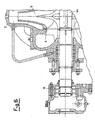
- Figure 1 is a sectional view of the pump according to the invention;
- Figure 2 is a sectional view of a detail of the pump according to the invention;
- Figure 3 is a side elevation view of the pump according to the invention;
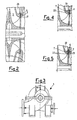
- Figure 4 is a sectional view of a detail of the pump according to the invention and according to a second embodiment;
- Figure 5 is a sectional view of a detail of the pump according to the invention and according to a third embodiment;
- Figure 6 is a sectional view of a detail of the pump according to the invention and according to a fourth embodiment;
- Referring to the above figures, a centrifugal pump, indicated by numeral 1, is shown, wherein a shaft 4, on which an
impeller 5 is splined, is rotatably connected within acasing 2. - The
casing 2 and theimpeller 5 have opposedsurfaces casing 2 through locking means 7, as for instance rivets, other mechanical devices and/or bonding agents, or, as in the example, screws. Theimpeller 5, during operation, transmits centrifugal forces to the water, said forces enhance the sealing efficiency since they move the water away from the axis of theimpeller 5. - Further, the
ring 6 allows the automatic centering of theimpeller 5 within thecasing 2 without the need of providing proper axial locking elements. In fact, thering 6 can transmit axial forces to thecasing 2 and theimpeller 5, said forces maintain, in a natural and autonomous way, theimpeller 5 in its correct position inside thecasing 2. - In a different embodiment, the pump, according to the invention, has the
sealing ring 6 detachably connected to the impeller 5 (Figure 4) by means ofscrews 7; a further embodiment of the pump according to the invention has a couple ofsealing rings 6 so that a first ring is connected to theimpeller 5 and a second ring is connected to the casing 2 (Figure 5). - The
rings 6 are made of wearing materials with a low friction coefficient in order to have a wearing element which will be changed when the material deterioration is such that it does not guarantee the pump proper operation any more. Said rings are preferably made of synthetic fibers, ceramic materails, sintered powders, ferrous materials coated with suitable materials, for instance chromium plated cast iron rings. - The shaft 4 is rotatably connected to the
casing 2 by means of twoplain bearings cylindrical housing casing 2. At the ends of thehousings ledge 18 to allow the detachable connection of acover 10 or of sealing means 12. - The
cover 10 closes saidhousing 8 and forms afirst chamber 11 suitable to contain water. Further, thecover 10 can have an opening to connect saidchamber 11 with the outside environment, said opening being closed by means of a threadedcap 17. - A
hydraulic connection device 16 connectschamber 11 with ahigh pressure chamber 20, so as to allow the passage of the water fromchamber 20 tochamber 11, this will allow the lubrication of the plain bearing 23, since saidchamber 11 is in communication with said bearing. - The
housing 9, wherein thesecond plain bearing 24 is positioned, has its front portion closed by thesealing means 12, which allows the shaft 4 to project from thepump casing 2 and to be connected to a drive machine not shown in the figures. The sealing means 12 define, at the end of thehousing 9 of thebearing 24, achamber 14 which faces thebearing 24, said chamber is connected to thehigh pressure chamber 20 through ahydraulic connection device 16 and through the sealing means 12. Therefore, the water coming from thehigh pressure chamber 20 lubricates both thebearing 23 positioned in thehousing 8 and thebearing 24 positioned in thehousing 9. - A further embodiment of the pump according to the invention has sealing
rings 6 positioned between thecasing 2 and theimpeller 5, said rings exert, according to the invention, their sealing action along radial surfaces, andball bearings 30 which support the shaft 44 (Figure 6). - Another embodiment of the pump according to the invention has sealing rings which exert their sealing action along radial surfaces, and roller bearings which support the shaft and rotatably connect said shaft to the casing.
- In this pump embodiment, there is no need for axial locking devices since the sealing ring performs this function (not shown).
- The pump operation, according to the invention, is as follows.
- The pump inlet water is sent into a
low pressure chamber 19 by theimpeller 5 which gives up energyto the water, puts said water under high pressure and discharges it into ahigh pressure chamber 20. - The seal between the
chambers sealing rings 6, which, since they are detachably connected to thecasing 2, move in relation to theimpeller 5. Said rings obstruct very efficiently the passage of the water from the high pressure chamber to the low pressure chamber, since the centrifugal forces, transmitted to the water by the impeller, help the execution of said obstructing action. - In a simplified embodiment (not shown), the room taken by the ring or the rings is taken by corresponding portions of the
casing 2 and of theimpeller 5 and the seal is realised along theopposed surfaces - Further, the pump shaft, according to the invention, is rotatably connected to the
casing 2 by means of a couple ofplain bearings high pressure chamber 20 through theconnection devices 16. - The pump, according to the invention, does not need axial bearings or other components suitable to exert axial forces; in fact, the
sealing rings 6 themselves allow the force exchange along the axis, between theimpeller 5 and thecasing 2. - In practice, it has been observed that the pump, according to the invention, is particularly advantageous because of the high attainable efficiency. Further, the pump is particularly advantageous from an environmental point of view since it reduces the noise and the polluting agents as exhausted greases and oils.
- Finally, the low manufacturing, maintenance and operation costs of said pump make the whole system inexpensive.
- The pump, as herein disclosed, can be subjected to several modifications and changes without leaving the scope of the invention; further, all the details can be replaced by technically equivalent elements.
- In practice, the materials and the dimensions can be changed at will according to the needs.
Claims (10)
- A radially sealed centrifugal pump comprises a casing (2) to which a shaft (4) is rotatably connected, and an impeller (5), connected to said shaft (4), and free to rotate within said casing (2), said casing (2) and said impeller (5), which are in relative motion, have opposed surfaces (21, 22) which are substantially perpendicular to the axis of said impeller (5) and which form the seal characterised in that said seal comprises at least a sealing ring (6) which is detachably connected by locking elements (7), said pump comprising at least plain bearings (23, 24) positioned in substantially cylindrical housings (8, 9) of the casing (2), said bearings (23, 24) being positioned between said casing (2) and said shaft (4) and being lubricated by the same liquid treated by the pump.
- A centrifugal pump as claimed in claim 1, characterised by comprising sealing and protection sliding means (6), positioned between said surfaces (21, 22) in relative motion, in order to improve the sealing action and to protect the pump main components from possible mutual contacts or from fluid impurities.
- A centrifugal pump as claimed in claim 1, characterised in that said ring is detachably connected at least to the impeller (5).
- A centrifugal pump as claimed in claim 1, characterised in that said ring is detachably connected at least to the casing (2).
- A centrifugal pump as claimed in claim 1, characterised in that said sealing rings (6) are made of a low friction coefficient material.
- A centrifugal pump as claimed in claim 1, characterised in that said locking elements (7) are screws.
- A centrifugal pump as claimed in claim 1, characterised in that the front portion of said first housing (8) is closed by a cover (10), which defines a first chamber (11) hydraulically connected to said plain bearings (23).
- A centrifugal pump as claimed in claim 1, characterised in that said casing (2) has, close to said second housing (9), sealing means (12) associated with said shaft (4), which define at least a second chamber (14) hydraulically connected to said plain bearings (24).
- A centrifugal pump as claimed in claim 7, characterised by having at least a hydraulic connection device (16) between said first chamber (11) and a pump high pressure chamber (20), in order to supply the necessary lubricating fluid to said bearing (23).
- A centrifugal pump as claimed in claim 8, characterised by having a hydraulic connection device (16) between said second chamber (14) and said pump high pressure chamber (20), in order to supply the necessary lubricating fluid to said bearing (24).
Applications Claiming Priority (2)
| Application Number | Priority Date | Filing Date | Title |
|---|---|---|---|
| IT98MI001112A ITMI981112A1 (en) | 1998-05-20 | 1998-05-20 | CENTRIFUGAL PUMP WITH RADIAL SEAL |
| ITMI981112 | 1998-05-20 |
Publications (3)
| Publication Number | Publication Date |
|---|---|
| EP0959254A1 EP0959254A1 (en) | 1999-11-24 |
| EP0959254B1 EP0959254B1 (en) | 2001-09-19 |
| EP0959254B2 true EP0959254B2 (en) | 2006-03-22 |
Family
ID=11380067
Family Applications (1)
| Application Number | Title | Priority Date | Filing Date |
|---|---|---|---|
| EP98203806A Expired - Lifetime EP0959254B2 (en) | 1998-05-20 | 1998-11-11 | Radially sealed centrifugal pump |
Country Status (8)
| Country | Link |
|---|---|
| US (1) | US6004094A (en) |
| EP (1) | EP0959254B2 (en) |
| AT (1) | ATE205915T1 (en) |
| DE (2) | DE69801740T3 (en) |
| DK (1) | DK0959254T3 (en) |
| ES (1) | ES2163232T3 (en) |
| IT (1) | ITMI981112A1 (en) |
| PT (1) | PT959254E (en) |
Families Citing this family (7)
| Publication number | Priority date | Publication date | Assignee | Title |
|---|---|---|---|---|
| ITMI20010592A1 (en) * | 2001-03-21 | 2002-09-21 | Umberto Cambiaghi | CENTRIFUGAL PUMP WITH RADIAL AXIAL CLEARANCE ADJUSTMENT WITHOUT OPENING THE PUMP BODY |
| RU2187713C1 (en) * | 2001-07-13 | 2002-08-20 | Центр внедрения новых технологий Центрального института авиационного моторостроения им. П.И.Баранова | Centrifugal pump |
| DE102005012165B4 (en) * | 2005-03-17 | 2007-02-08 | L'orange Gmbh | Fuel accumulator of a fuel injection system for multi-cylinder internal combustion engine and flow control valve for such |
| JP2007309440A (en) * | 2006-05-19 | 2007-11-29 | Hitachi Plant Technologies Ltd | Shaft sealing device for rotating shaft penetrating portion and pump using the same |
| DE102010023931A1 (en) * | 2010-06-16 | 2011-12-22 | Allweiler Ag | Double-flow centrifugal pump |
| US9488184B2 (en) | 2012-05-02 | 2016-11-08 | King Abdulaziz City For Science And Technology | Method and system of increasing wear resistance of a part of a rotating mechanism exposed to fluid flow therethrough |
| US8721262B1 (en) * | 2013-11-11 | 2014-05-13 | Alexander Ivanovich Kuropatov | Vertical centrifugal pump |
Family Cites Families (16)
| Publication number | Priority date | Publication date | Assignee | Title |
|---|---|---|---|---|
| DE142214C (en) * | ||||
| US794185A (en) * | 1904-07-21 | 1905-07-11 | Laval Steam Turbine Co | Wearing-ring for centrifugal pumps. |
| FR355951A (en) * | 1905-07-07 | 1905-11-17 | Louis Armand Dumont | Improvements to centrifugal pumps and horizontal axis drive turbines |
| GB186243A (en) * | 1921-09-02 | 1922-09-28 | John Hargrove | Improvements in or connected with centrifugal pumps |
| US1545608A (en) * | 1924-10-31 | 1925-07-14 | Frederick Iron & Steel Company | Centrifugal pump |
| GB292609A (en) * | 1927-06-23 | 1928-08-02 | Gen Electric | Improvements in or relating to packings for stuffing boxes |
| US1999163A (en) * | 1929-06-04 | 1935-04-23 | Allen Sherman Hoff Co | Centrifugal pump |
| US1967182A (en) * | 1934-04-03 | 1934-07-17 | Allen Sherman Hoff Co | Centrifugal pump |
| DE639105C (en) * | 1934-11-18 | 1936-11-28 | Rudolf Duemmerling | Multi-stage centrifugal pump with radial gap sealing surfaces |
| FR2409406A1 (en) * | 1977-11-22 | 1979-06-15 | Air Liquide | PROCESS FOR REALIZING THE INTERNAL SEALS AND SHAFT OUTLET OF A PUMP AND PUMP IMPLEMENTING THIS PROCESS |
| US4208166A (en) * | 1978-05-15 | 1980-06-17 | Allis-Chalmers Corporation | Adjustable wear ring for a centrifugal pump |
| US4501530A (en) * | 1982-08-13 | 1985-02-26 | A. W. Chesterton Company | Centrifugal pump |
| US4913619A (en) * | 1988-08-08 | 1990-04-03 | Barrett Haentjens & Co. | Centrifugal pump having resistant components |
| DE3943273C2 (en) * | 1989-12-29 | 1996-07-18 | Klaus Union Armaturen | Horizontal centrifugal pump with canned magnetic coupling |
| JPH08232892A (en) * | 1995-02-27 | 1996-09-10 | Unisia Jecs Corp | Closed type pump |
| US5779434A (en) * | 1997-02-06 | 1998-07-14 | Baker Hughes Incorporated | Pump mounted thrust bearing |
-
1998
- 1998-05-20 IT IT98MI001112A patent/ITMI981112A1/en unknown
- 1998-11-10 US US09/189,292 patent/US6004094A/en not_active Expired - Lifetime
- 1998-11-11 DE DE69801740T patent/DE69801740T3/en not_active Expired - Lifetime
- 1998-11-11 PT PT98203806T patent/PT959254E/en unknown
- 1998-11-11 DE DE0959254T patent/DE959254T1/en active Pending
- 1998-11-11 DK DK98203806T patent/DK0959254T3/en active
- 1998-11-11 AT AT98203806T patent/ATE205915T1/en not_active IP Right Cessation
- 1998-11-11 ES ES98203806T patent/ES2163232T3/en not_active Expired - Lifetime
- 1998-11-11 EP EP98203806A patent/EP0959254B2/en not_active Expired - Lifetime
Also Published As
| Publication number | Publication date |
|---|---|
| DE69801740T2 (en) | 2002-07-04 |
| ES2163232T3 (en) | 2002-01-16 |
| US6004094A (en) | 1999-12-21 |
| EP0959254B1 (en) | 2001-09-19 |
| DE959254T1 (en) | 2001-05-03 |
| DK0959254T3 (en) | 2002-01-07 |
| DE69801740T3 (en) | 2006-11-16 |
| DE69801740D1 (en) | 2001-10-25 |
| ITMI981112A1 (en) | 1999-11-20 |
| ATE205915T1 (en) | 2001-10-15 |
| EP0959254A1 (en) | 1999-11-24 |
| PT959254E (en) | 2002-02-28 |
Similar Documents
| Publication | Publication Date | Title |
|---|---|---|
| KR890001725B1 (en) | Rotary fluid handling machine having reduced fluid leakage | |
| US6379127B1 (en) | Submersible motor with shaft seals | |
| US5009578A (en) | Motor driven pumps | |
| EP1222393B1 (en) | Submersible motor with shaft seals | |
| WO2020156089A1 (en) | Deep water pump having pressure compensation function | |
| US2958292A (en) | Canned motor | |
| CA2150293C (en) | Centrifugal pump | |
| RU2218480C2 (en) | Fluid media handling machine (versions) | |
| US5558491A (en) | Unitized product seal for pumps | |
| US3500961A (en) | Pressure balanced bearing lubrication system | |
| EP0959254B2 (en) | Radially sealed centrifugal pump | |
| EP2745017B1 (en) | Bearing assembly for a vertical turbine pump | |
| US3292847A (en) | Lubricant sealing means for rotary positive displacement pump | |
| EP1229269A1 (en) | Power transmission device | |
| US4108569A (en) | Lubricated mechanical seals for pumps | |
| EP4030065B1 (en) | Rotary pump with axial thrust balancing drum and regulation of a leakage flow | |
| EP3857072B1 (en) | A multistage pump with axial thrust optimization | |
| EP0165689B1 (en) | An automatic lubricating device for machine shafts | |
| EP3545174B1 (en) | Shaft seal including an upstream non-contact part, e.g. a labyrinth seal, and a downstream slinger | |
| US7748951B2 (en) | Bearing housing seal system for centrifugal pumps | |
| EP1452740A2 (en) | Hydrodynamic sealing system for centrifugal systems | |
| Watterson | Rotating Equipment: Maintenance and Troubleshooting | |
| CN114450490B (en) | Pump arrangements and mechanical shaft seals for pumping barrier liquids | |
| EP2748496B1 (en) | Apparatus for pumping a fluid | |
| EP3384186B1 (en) | Static shaft sealing |
Legal Events
| Date | Code | Title | Description |
|---|---|---|---|
| PUAI | Public reference made under article 153(3) epc to a published international application that has entered the european phase |
Free format text: ORIGINAL CODE: 0009012 |
|
| AK | Designated contracting states |
Kind code of ref document: A1 Designated state(s): AT BE CH CY DE DK ES FI FR GB GR IE IT LI LU MC NL PT SE |
|
| AX | Request for extension of the european patent |
Free format text: AL;LT;LV;MK;RO;SI |
|
| 17P | Request for examination filed |
Effective date: 20000519 |
|
| AKX | Designation fees paid |
Free format text: AT BE CH CY DE DK ES FI FR GB GR IE IT LI LU MC NL PT SE |
|
| AXX | Extension fees paid |
Free format text: AL PAYMENT 20000519;LT PAYMENT 20000519;LV PAYMENT 20000519;MK PAYMENT 20000519;RO PAYMENT 20000519;SI PAYMENT 20000519 |
|
| RAP1 | Party data changed (applicant data changed or rights of an application transferred) |
Owner name: TM.P. S.P.A.- TERMOMECCANICA POMPE |
|
| 17Q | First examination report despatched |
Effective date: 20001204 |
|
| GRAG | Despatch of communication of intention to grant |
Free format text: ORIGINAL CODE: EPIDOS AGRA |
|
| GRAG | Despatch of communication of intention to grant |
Free format text: ORIGINAL CODE: EPIDOS AGRA |
|
| GRAH | Despatch of communication of intention to grant a patent |
Free format text: ORIGINAL CODE: EPIDOS IGRA |
|
| DET | De: translation of patent claims | ||
| GRAH | Despatch of communication of intention to grant a patent |
Free format text: ORIGINAL CODE: EPIDOS IGRA |
|
| GRAA | (expected) grant |
Free format text: ORIGINAL CODE: 0009210 |
|
| AK | Designated contracting states |
Kind code of ref document: B1 Designated state(s): AT BE CH CY DE DK ES FI FR GB GR IE IT LI LU MC NL PT SE |
|
| AX | Request for extension of the european patent |
Free format text: AL PAYMENT 20000519;LT PAYMENT 20000519;LV PAYMENT 20000519;MK PAYMENT 20000519;RO PAYMENT 20000519;SI PAYMENT 20000519 |
|
| LTIE | Lt: invalidation of european patent or patent extension | ||
| REF | Corresponds to: |
Ref document number: 205915 Country of ref document: AT Date of ref document: 20011015 Kind code of ref document: T |
|
| REG | Reference to a national code |
Ref country code: CH Ref legal event code: EP |
|
| REG | Reference to a national code |
Ref country code: IE Ref legal event code: FG4D |
|
| REF | Corresponds to: |
Ref document number: 69801740 Country of ref document: DE Date of ref document: 20011025 |
|
| PG25 | Lapsed in a contracting state [announced via postgrant information from national office to epo] |
Ref country code: LU Free format text: LAPSE BECAUSE OF NON-PAYMENT OF DUE FEES Effective date: 20011130 |
|
| REG | Reference to a national code |
Ref country code: CH Ref legal event code: NV Representative=s name: AMMANN PATENTANWAELTE AG BERN |
|
| REG | Reference to a national code |
Ref country code: GB Ref legal event code: IF02 |
|
| REG | Reference to a national code |
Ref country code: DK Ref legal event code: T3 |
|
| REG | Reference to a national code |
Ref country code: ES Ref legal event code: FG2A Ref document number: 2163232 Country of ref document: ES Kind code of ref document: T3 |
|
| ET | Fr: translation filed | ||
| REG | Reference to a national code |
Ref country code: PT Ref legal event code: SC4A Free format text: AVAILABILITY OF NATIONAL TRANSLATION Effective date: 20011130 |
|
| REG | Reference to a national code |
Ref country code: GR Ref legal event code: EP Ref document number: 20010402321 Country of ref document: GR |
|
| PLBI | Opposition filed |
Free format text: ORIGINAL CODE: 0009260 |
|
| PLBF | Reply of patent proprietor to notice(s) of opposition |
Free format text: ORIGINAL CODE: EPIDOS OBSO |
|
| 26 | Opposition filed |
Opponent name: KSB AKTIENGESELLSCHAFT Effective date: 20020617 |
|
| NLR1 | Nl: opposition has been filed with the epo |
Opponent name: KSB AKTIENGESELLSCHAFT |
|
| PLBF | Reply of patent proprietor to notice(s) of opposition |
Free format text: ORIGINAL CODE: EPIDOS OBSO |
|
| PLBF | Reply of patent proprietor to notice(s) of opposition |
Free format text: ORIGINAL CODE: EPIDOS OBSO |
|
| PGFP | Annual fee paid to national office [announced via postgrant information from national office to epo] |
Ref country code: GR Payment date: 20040924 Year of fee payment: 7 |
|
| PGFP | Annual fee paid to national office [announced via postgrant information from national office to epo] |
Ref country code: CY Payment date: 20041004 Year of fee payment: 7 |
|
| PGFP | Annual fee paid to national office [announced via postgrant information from national office to epo] |
Ref country code: MC Payment date: 20041027 Year of fee payment: 7 |
|
| PGFP | Annual fee paid to national office [announced via postgrant information from national office to epo] |
Ref country code: NL Payment date: 20041103 Year of fee payment: 7 |
|
| PGFP | Annual fee paid to national office [announced via postgrant information from national office to epo] |
Ref country code: PT Payment date: 20041104 Year of fee payment: 7 |
|
| PGFP | Annual fee paid to national office [announced via postgrant information from national office to epo] |
Ref country code: SE Payment date: 20041105 Year of fee payment: 7 |
|
| PGFP | Annual fee paid to national office [announced via postgrant information from national office to epo] |
Ref country code: FR Payment date: 20041109 Year of fee payment: 7 |
|
| PGFP | Annual fee paid to national office [announced via postgrant information from national office to epo] |
Ref country code: AT Payment date: 20041111 Year of fee payment: 7 Ref country code: IE Payment date: 20041111 Year of fee payment: 7 |
|
| PGFP | Annual fee paid to national office [announced via postgrant information from national office to epo] |
Ref country code: FI Payment date: 20041112 Year of fee payment: 7 |
|
| PGFP | Annual fee paid to national office [announced via postgrant information from national office to epo] |
Ref country code: LU Payment date: 20041116 Year of fee payment: 7 Ref country code: DK Payment date: 20041116 Year of fee payment: 7 |
|
| PGFP | Annual fee paid to national office [announced via postgrant information from national office to epo] |
Ref country code: ES Payment date: 20041214 Year of fee payment: 7 |
|
| PGFP | Annual fee paid to national office [announced via postgrant information from national office to epo] |
Ref country code: BE Payment date: 20050215 Year of fee payment: 7 |
|
| PG25 | Lapsed in a contracting state [announced via postgrant information from national office to epo] |
Ref country code: FI Free format text: LAPSE BECAUSE OF NON-PAYMENT OF DUE FEES Effective date: 20050322 |
|
| PG25 | Lapsed in a contracting state [announced via postgrant information from national office to epo] |
Ref country code: IE Free format text: LAPSE BECAUSE OF NON-PAYMENT OF DUE FEES Effective date: 20051111 Ref country code: CY Free format text: LAPSE BECAUSE OF NON-PAYMENT OF DUE FEES Effective date: 20051111 Ref country code: AT Free format text: LAPSE BECAUSE OF NON-PAYMENT OF DUE FEES Effective date: 20051111 |
|
| PG25 | Lapsed in a contracting state [announced via postgrant information from national office to epo] |
Ref country code: SE Free format text: LAPSE BECAUSE OF NON-PAYMENT OF DUE FEES Effective date: 20051112 |
|
| PG25 | Lapsed in a contracting state [announced via postgrant information from national office to epo] |
Ref country code: MC Free format text: LAPSE BECAUSE OF NON-PAYMENT OF DUE FEES Effective date: 20051130 Ref country code: DK Free format text: LAPSE BECAUSE OF NON-PAYMENT OF DUE FEES Effective date: 20051130 Ref country code: BE Free format text: LAPSE BECAUSE OF NON-PAYMENT OF DUE FEES Effective date: 20051130 |
|
| PUAH | Patent maintained in amended form |
Free format text: ORIGINAL CODE: 0009272 |
|
| STAA | Information on the status of an ep patent application or granted ep patent |
Free format text: STATUS: PATENT MAINTAINED AS AMENDED |
|
| 27A | Patent maintained in amended form |
Effective date: 20060322 |
|
| AK | Designated contracting states |
Kind code of ref document: B2 Designated state(s): AT BE CH CY DE DK ES FI FR GB GR IE IT LI LU MC NL PT SE |
|
| AX | Request for extension of the european patent |
Extension state: AL LT LV MK RO SI |
|
| REG | Reference to a national code |
Ref country code: CH Ref legal event code: AEN Free format text: MAINTIEN DU BREVET DONT L'ETENDUE A ETE MODIFIEE |
|
| PG25 | Lapsed in a contracting state [announced via postgrant information from national office to epo] |
Ref country code: PT Free format text: LAPSE BECAUSE OF NON-PAYMENT OF DUE FEES Effective date: 20060511 |
|
| NLR2 | Nl: decision of opposition |
Effective date: 20060322 |
|
| PG25 | Lapsed in a contracting state [announced via postgrant information from national office to epo] |
Ref country code: NL Free format text: LAPSE BECAUSE OF NON-PAYMENT OF DUE FEES Effective date: 20060601 |
|
| PG25 | Lapsed in a contracting state [announced via postgrant information from national office to epo] |
Ref country code: ES Free format text: LAPSE BECAUSE OF FAILURE TO SUBMIT A TRANSLATION OF THE DESCRIPTION OR TO PAY THE FEE WITHIN THE PRESCRIBED TIME-LIMIT Effective date: 20060703 |
|
| REG | Reference to a national code |
Ref country code: DK Ref legal event code: EBP |
|
| EUG | Se: european patent has lapsed | ||
| PG25 | Lapsed in a contracting state [announced via postgrant information from national office to epo] |
Ref country code: FR Free format text: LAPSE BECAUSE OF NON-PAYMENT OF DUE FEES Effective date: 20060731 |
|
| REG | Reference to a national code |
Ref country code: PT Ref legal event code: MM4A Effective date: 20060511 |
|
| NLV4 | Nl: lapsed or anulled due to non-payment of the annual fee |
Effective date: 20060601 |
|
| REG | Reference to a national code |
Ref country code: IE Ref legal event code: MM4A |
|
| REG | Reference to a national code |
Ref country code: FR Ref legal event code: ST Effective date: 20060731 |
|
| EN | Fr: translation not filed | ||
| BERE | Be: lapsed |
Owner name: TERMOMECCANICA POMPE S.P.A. *TMP Effective date: 20051130 |
|
| PG25 | Lapsed in a contracting state [announced via postgrant information from national office to epo] |
Ref country code: GR Free format text: LAPSE BECAUSE OF FAILURE TO SUBMIT A TRANSLATION OF THE DESCRIPTION OR TO PAY THE FEE WITHIN THE PRESCRIBED TIME-LIMIT Effective date: 20010919 |
|
| PGFP | Annual fee paid to national office [announced via postgrant information from national office to epo] |
Ref country code: CH Payment date: 20121113 Year of fee payment: 15 Ref country code: DE Payment date: 20121107 Year of fee payment: 15 |
|
| PGFP | Annual fee paid to national office [announced via postgrant information from national office to epo] |
Ref country code: GB Payment date: 20121107 Year of fee payment: 15 |
|
| REG | Reference to a national code |
Ref country code: CH Ref legal event code: PL |
|
| GBPC | Gb: european patent ceased through non-payment of renewal fee |
Effective date: 20131111 |
|
| PG25 | Lapsed in a contracting state [announced via postgrant information from national office to epo] |
Ref country code: CH Free format text: LAPSE BECAUSE OF NON-PAYMENT OF DUE FEES Effective date: 20131130 Ref country code: LI Free format text: LAPSE BECAUSE OF NON-PAYMENT OF DUE FEES Effective date: 20131130 |
|
| REG | Reference to a national code |
Ref country code: DE Ref legal event code: R119 Ref document number: 69801740 Country of ref document: DE Effective date: 20140603 |
|
| PG25 | Lapsed in a contracting state [announced via postgrant information from national office to epo] |
Ref country code: DE Free format text: LAPSE BECAUSE OF NON-PAYMENT OF DUE FEES Effective date: 20140603 |
|
| PG25 | Lapsed in a contracting state [announced via postgrant information from national office to epo] |
Ref country code: GB Free format text: LAPSE BECAUSE OF NON-PAYMENT OF DUE FEES Effective date: 20131111 |
|
| PGFP | Annual fee paid to national office [announced via postgrant information from national office to epo] |
Ref country code: IT Payment date: 20171124 Year of fee payment: 20 |