EP0959208A1 - Sicherheitsauslösevorrichtung - Google Patents
Sicherheitsauslösevorrichtung Download PDFInfo
- Publication number
- EP0959208A1 EP0959208A1 EP98850074A EP98850074A EP0959208A1 EP 0959208 A1 EP0959208 A1 EP 0959208A1 EP 98850074 A EP98850074 A EP 98850074A EP 98850074 A EP98850074 A EP 98850074A EP 0959208 A1 EP0959208 A1 EP 0959208A1
- Authority
- EP
- European Patent Office
- Prior art keywords
- locking
- door
- safety release
- actuating lever
- release assembly
- Prior art date
- Legal status (The legal status is an assumption and is not a legal conclusion. Google has not performed a legal analysis and makes no representation as to the accuracy of the status listed.)
- Withdrawn
Links
- 238000007789 sealing Methods 0.000 claims description 21
- 239000000463 material Substances 0.000 claims description 9
- 230000007797 corrosion Effects 0.000 claims description 5
- 238000005260 corrosion Methods 0.000 claims description 5
- 239000007769 metal material Substances 0.000 claims description 3
- 230000035515 penetration Effects 0.000 claims description 3
- XAGFODPZIPBFFR-UHFFFAOYSA-N aluminium Chemical compound [Al] XAGFODPZIPBFFR-UHFFFAOYSA-N 0.000 description 3
- 229910052782 aluminium Inorganic materials 0.000 description 3
- 239000004411 aluminium Substances 0.000 description 3
- 229920001343 polytetrafluoroethylene Polymers 0.000 description 3
- 239000004810 polytetrafluoroethylene Substances 0.000 description 3
- 229910001220 stainless steel Inorganic materials 0.000 description 3
- 239000010935 stainless steel Substances 0.000 description 3
- 230000000694 effects Effects 0.000 description 2
- 238000004519 manufacturing process Methods 0.000 description 2
- 239000011490 mineral wool Substances 0.000 description 2
- 230000000717 retained effect Effects 0.000 description 2
- 238000003466 welding Methods 0.000 description 2
- 230000006835 compression Effects 0.000 description 1
- 238000007906 compression Methods 0.000 description 1
- 238000010276 construction Methods 0.000 description 1
- 230000001419 dependent effect Effects 0.000 description 1
- 238000001035 drying Methods 0.000 description 1
- 239000003344 environmental pollutant Substances 0.000 description 1
- 238000009413 insulation Methods 0.000 description 1
- 239000012774 insulation material Substances 0.000 description 1
- 230000004048 modification Effects 0.000 description 1
- 238000012986 modification Methods 0.000 description 1
- 230000001590 oxidative effect Effects 0.000 description 1
- 239000004033 plastic Substances 0.000 description 1
- 231100000719 pollutant Toxicity 0.000 description 1
- 229920001296 polysiloxane Polymers 0.000 description 1
- -1 polytetrafluoroethylene Polymers 0.000 description 1
- 239000002023 wood Substances 0.000 description 1
Images


Classifications
-
- E—FIXED CONSTRUCTIONS
- E05—LOCKS; KEYS; WINDOW OR DOOR FITTINGS; SAFES
- E05B—LOCKS; ACCESSORIES THEREFOR; HANDCUFFS
- E05B83/00—Vehicle locks specially adapted for particular types of wing or vehicle
- E05B83/02—Locks for railway freight-cars, freight containers or the like; Locks for the cargo compartments of commercial lorries, trucks or vans
- E05B83/08—Locks for railway freight-cars, freight containers or the like; Locks for the cargo compartments of commercial lorries, trucks or vans with elongated bars for actuating the fastening means
- E05B83/10—Rotary bars
-
- E—FIXED CONSTRUCTIONS
- E05—LOCKS; KEYS; WINDOW OR DOOR FITTINGS; SAFES
- E05B—LOCKS; ACCESSORIES THEREFOR; HANDCUFFS
- E05B65/00—Locks or fastenings for special use
- E05B65/0042—For refrigerators or cold rooms
- E05B65/0053—For refrigerators or cold rooms with safety release from inside
Definitions
- the present invention relates generally to a safety release assembly, and more specifically to an safety release mechanism which is designed for use with climate chambers, or the like.
- a safety release mechanism for the doors of freight containers is shown in GB A 2 154 646.
- Said mechanism comprises a lever for rotating an operating bar which is equipped with locking cams.
- Said lever is in locked condition secured to a retainer, which in turn, is held fast with the door by permanent fixings.
- the emergency release mechanism provides releasable fixings for the retainer, which can be released from the inside by turning pins.
- GB 1 490 651 discloses a door lock and safety release mechanism of a type where the locking mechanism is a rotatable locking bar, which when rotated engage separate keeper members. The rotation is effected by turning a hand lever, which, when the locking bar has been rotated into engagement with the keeper members is held by retainer means.
- Said retainer means comprises a hub, which is held in the door by a threaded rod screwed into said door. Said rod extends though the door, on the inside of which is found the safety release mechanism.
- a rotatable mechanism On the inside of the door is arranged a rotatable mechanism, by means of which the threaded rod can be unscrewed from its engagement with the door, which in turns has the effect that the hub, holding the retainer means assembly, is pushed in an outward direction in relation to the door, thereby also pushing the hand lever in the same direction. Since the hand lever is connected to the locking bar, the outward movement of the hand lever causes the locking bar to rotate, which rotation disengages the radially extending portions of the locking bar from the keeper members.
- EP A 0 580 911 Another safety opening device is disclosed in EP A 0 580 911, in which the portion of the door onto which the locking member, padlock or the like is attached, is removable by releasing a mechanism which locks said door portion, and subsequently pushing said door portion outwardly, thereby achieving the effect of also pushing aside and turning into open position the locking mechanism of the door to be locked.
- US 2 636 767 discloses a mechanism, which functions in a manner which is parallel to the mode of function of GB A 2 154 646, i.e. that a retaining element which is screwed to the door may be unscrewed from the inside.
- Another salient problem is the sealing of all openings, the most important being the opening through the door, which houses parts of the safety release mechanism. If the corrosive climate is allowed to leak though an opening in the door, parts arranged on the outer side of the door may be affected by this, causing corrosion to vital parts, and maybe even the door itself, which is, of course, is very costly. Further, such leakage is of course influencing the power consumption of climate control devices inside such chambers. This constitutes a serious problem for the above cited devices.
- Another desired characteristic feature is easy actuation of the safety release mechanism.
- Most prior art devices require that a threaded rod or the like need to be unscrewed from the inside, before the door may be opened. After use of the safety release mechanism, it has to be refitted, i.e. screwed back in place, or remounted.
- Yet another desired characteristic is the possibility of using such a device with a door which previously lacked a safety release mechanism.
- a safety release mechanism which may be manufactured in materials resistant to corrosion at a low cost, which safety release mechanism is arranged in such a way as to completely seal off the climate within the room to which the door leads, and which is easy to actuate, may be returned to locking position with the same ease, and which is, finally, easy to fit in a door which previously lacked a safety release mechanism.
- the drawbacks of prior art devices are overcome by the safety mechanism according to the invention, by providing, on the inside of the door, a lever and a simple releasable lever retaining device, which allows locking of a door from the outside only when the retainer device is in its locking mode.
- the retaining device is released, and the lever is removed from its retained position, it is impossible to lock the door from the outside. If, inadvertently, the door was locked from the outside, i.e. with the safety mechanism activated, the lock is rendered inoperative simply by raising said lever, and the door may be opened from the inside.
- the inventive safety mechanism is defined in claim 1.
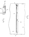
- Fig. 1 shows an exploded view of a safety release assembly according to the present invention.
- the assembly comprises a connecting rod 1 of tubular shape, which is rotatably mounted in a hole 2 in a door D which is to be locked.
- the connecting rod 1 has a locking bracket 4 attached to a first end thereof, which locking bracket 4 has a forward portion with the general shape of a "T" in plan view (the shape can be seen in fig. 2), and has a slot 4b for receiving a locking arm.
- the second end of the connecting rod is adapted for pivotable attachment to an actuating arm 5, e.g. by means of a locking screw (not shown) in a hole 3.
- the actuating arm 5 is comprised of a tubular rod, to a first end of which is attached, e.g. by means of welding in the case of a metallic material, two parallel flanges 6 having cam surfaces 6a and mutually concentric holes 6b, for receiving the above mentioned locking screw which pivotably joins the connecting rod 1 and the actuating arm 5, thus enabling the actuating arm 5 to be moved between a first, or retaining position, and a second position in which it is freely movable.
- the second end of the tubular rod 5, as well as the end of the connecting rod which is located on the inside of the door may advantageously be sealed by appropriate means, such as an end hat.
- Said second end of the actuating arm 5 is, in the retaining position received by retaining means 7, pivotably mounted to door D, as shown in the figure 1, and designed so as to prevent movement of the arm 5 in retaining position.
- Retaining means 7 comprise a bracket 8, having the general shape of a "U” (see fig. 4a), which is pivotable around pivots 8a, and has a handle knob 7b affixed thereto for ease of actuation of retainer means 7 by a user.
- Retaining means 7 is provided with means for adjustably applying a desired bias force to the actuating arm 5, as will be explained below.
- a mount 1a for the connecting rod in order to ensure that the locking bracket 4 is positioned at a suitable distance from the door, a distance which depends on the individual door, and for receiving the load which is applied to the assembly of the connecting rod 1 and the mount, especially in the case of a door with a soft insulation material, such as mineral wool or the like, which would otherwise be deformed.
- This bias forced is applied in order to compress into a sealing condition, at least one sealing member 1b, which is arranged on the inner surface of the door.
- the sealing member In operating mode, as will be explained below, the sealing member is compressed by the cam surfaces 6a of the actuating lever 5 acting on a washer 1c which is placed between the sealing member 1b and the cam surfaces, in order to achieve a good sealing.
- the sealing member 1b is preferably made of a material with high sealing and wear capability, such as silicone.
- Figure 2 shows a locking arm 9, preferably pivotable in the horizontal and the vertical directions, which is connected to a locking rod 11, which connects the locking arm 9 to a conventional locking mechanism, which is described further below, together with fig. 3.
- the locking bracket 4 has a slot 4b (see fig. 1) for receiving the locking arm 9.
- the locking arm 9 also has a hole 9a for receiving a locking device (not shown), which may be a padlock or the like.
- the locking bracket 4 has, as was mentioned above, the general shape of a "T", where the upper, horizontal bar of the "T" constitutes a locking flange arm 4b, which can co-operate with the locking device.
- the above mentioned conventional locking mechanism comprises hook-shaped locking members 10, extending radially from the locking rod 11.
- hook-shaped locking members 10 On the doorframe or other part of the structure in which the door is arranged, there are provided arch-shaped members 12, which are engagable by the hook-shaped locking members 10, when the locking rod 11 is rotated by moving the locking arm 9 (fig. 2) in an inward direction,
- FIG. 4 shows the details of the inventive assembly from the inside.
- the lever retaining means 7 is shown in a retaining position, in which it retains the actuating lever 5, which is received within a bracket of the retaining means 7.
- the bracket together with other details of the construction of the retaining means, is shown in perspective in fig. 4a.
- Said bracket 8 has mounted onto it a spherical handle knob 7b, which knob is gripped by a user when he or she wishes to operate the retaining means 7 in order to release the actuating arm 5.
- Adjustment means 7a (see fig. 1) is provided for adjusting the bias of the sealing member, as will be explained below.
- the inventive safety release assembly is set in operating mode by turning the locking bracket 4 into a position in which it can receive the locking arm 9. This is done by rotating the connecting rod 1, onto which the locking bracket 4 is fixed, preferably by welding, by gripping and turning the actuating lever 5.
- the locking bracket 4 is in receiving position on the outside of the door D when the actuating lever may be pivoted towards the door D and be received within the bracket 8 of the retaining means 7.
- the retaining means 7 is pivoted away from the actuating lever 5, the actuating lever 5 is pivoted towards the door D, whereby it is received within the bracket 8 of the retaining means 7 when said means 7 are pivoted back to the position which is shown in figure 3.
- the cam surfaces 6a When the actuating lever 5 is pivoted towards the door D, the cam surfaces 6a will eventually come to abut against the washer 1c, which is placed on top of the sealing member 1b. When the actuating lever 5 is pushed further, the cam surfaces 6a will act upon the washer 1c, and consequently the sealing member 1b, which preferably is of a shape which corresponds to the shape of the washer 1c. The sealing member 1b is thus compressed into a condition where it seals the connecting rod 1 penetration passage 2 through the door. In case that the sealing member 1b should be worn, it might be necessary to retain the actuating arm 5 in a position closer to the inside of the door, in order to achieve the desired compression of the sealing member 1b. For this case, the retaining means is provided with adjusting means 7a, e.g. an adjusting screw (see fig. 1), by means of which this may be achieved.
- adjusting means 7a e.g. an adjusting screw (see fig. 1)
- the connecting rod 1 penetrates the door D though a mount 1a with the form of a tube, which is flush with the inner surface of the door, and protrudes a predetermined distance on the outside of the door, said distance being determined for each individual door.
- This door mount 1a performs two functions. Firstly, by protruding a distance outwards from the surface of the door D, it keeps the locking bracket 4, at a predetermined distance from the door D, since the locking bracket 4 will abut against the end of said mount 1a.
- the locking bracket 4 abuts against the end of the mount 1a, it will serve to receive the force which is applied to the connecting rod 1, and thus the locking bracket 4, on the outside of the door, and to the surface of the door on the inside.
- This is important in the case of a door which comprises a thin sheet material, such as aluminium or stainless steel, and a soft insulation layer, such as mineral wool, or the like. In this case, the door will not be able to take up the load without deforming; therefore, the mount 1a is indispensable for doors thus constructed.
- the doors D When the inventive safety release assembly is in operating mode, the doors D is shut, and locked by pushing the locking arm 9 towards the door D, which brings the hook-shaped locking members 10 into engagement with the respective arch-shaped members 12.
- the locking arm 9 is then inserted into the slot 4a in the locking bracket 4 and is thus secured in a locked position.
- An appropriate locking device e.g. a padlock may then be inserted into the hole 9a in the locking arm 9, in order to prevent unauthorised access to the space inside of the door D, by simply lifting and pushing outwards the locking arm 9.
- the door D may be opened from the inside by means of the inventive safety release assembly. This is done by pushing the actuating rod 5 towards the door D, thereby releasing the outwardly directed force which acts upon the retaining means 7, which force results from the bias force applied on the connecting rod 1. After this force on the retaining means 7 is released, said retaining means 7 is pivoted in a direction away from the actuating rod 5, thereby releasing said actuating rod 5 from the retained position, to a second position, in which it is freely movable.
- the actuating rod 5 is then used to rotate the connecting rod 1, and thus the locking bracket 4 such, that the flange arm 4a, which prevents the locking arm 9 from being lifted up from the slot 4b, by obstructing the upward movement of the locking device, will be brought out of the position in which it is able to obstruct the upward movement of the locking arm 9.
- the connecting rod 1 and the locking bracket 4 have been rotated 180°, no part of the locking bracket 4 is able to obstruct the movement, in any direction, of the locking arm 9.
- This means that the door D is openable from the inside, simply by pushing the door D outwards, whereby the hook-shaped locking members 10 are urged to rotate around the arch-shaped members 12.
- Said disengagement means that the door D is free to be pushed open from the inside.
- the described embodiment of the present invention described above is intended for use with rooms with a relatively high temperature and humidity. All the parts of the safety release mechanism are, in order to withstand that highly corrosive environment, manufactured from a corrosion resistant material, such as pure aluminium, or stainless steel.
- the penetration passage 2 between the insulated climate inside the room, which may contain oxidative pollutants or the like, and the ambient atmosphere may be sealed by means of further sealing members.
- the safety release mechanism is adapted for use in cold storage facilities.
- the connecting rod 1 may be formed from two separate end portions, interconnected by means of a similarly shaped central connecting portion, in a plastic material, such as PTFE (polytetrafluoroethylene), or the like, with low thermal conductivity.
- PTFE polytetrafluoroethylene
- Yet another possibility consists in manufacturing the connecting rod in one piece from a material such as PTFE, although this reduces the resistance to wear.
- the padlock may be substituted by a conventional lock, or any other means which are capable of performing the same function.
- the retaining means could have any structure which permits releasable retaining of the actuating arm, and adjustment of the load in retaining, or locking position.
- the invention is, however, not limited by such detail. A great number of alternatives and modifications are conceivable, without departing from the scope of the present invention, which is defined, solely, by the appended claims.
Landscapes
- Physics & Mathematics (AREA)
- Thermal Sciences (AREA)
- Refrigerator Housings (AREA)
- Lock And Its Accessories (AREA)
Priority Applications (2)
| Application Number | Priority Date | Filing Date | Title |
|---|---|---|---|
| EP98850074A EP0959208A1 (de) | 1998-05-11 | 1998-05-11 | Sicherheitsauslösevorrichtung |
| NO992281A NO992281L (no) | 1998-05-11 | 1999-05-11 | Sikkerhetsfrigjöringsanordning |
Applications Claiming Priority (1)
| Application Number | Priority Date | Filing Date | Title |
|---|---|---|---|
| EP98850074A EP0959208A1 (de) | 1998-05-11 | 1998-05-11 | Sicherheitsauslösevorrichtung |
Publications (1)
| Publication Number | Publication Date |
|---|---|
| EP0959208A1 true EP0959208A1 (de) | 1999-11-24 |
Family
ID=8236973
Family Applications (1)
| Application Number | Title | Priority Date | Filing Date |
|---|---|---|---|
| EP98850074A Withdrawn EP0959208A1 (de) | 1998-05-11 | 1998-05-11 | Sicherheitsauslösevorrichtung |
Country Status (2)
| Country | Link |
|---|---|
| EP (1) | EP0959208A1 (de) |
| NO (1) | NO992281L (de) |
Cited By (4)
| Publication number | Priority date | Publication date | Assignee | Title |
|---|---|---|---|---|
| DE10143640C1 (de) * | 2001-09-06 | 2003-01-16 | Rational Ag | Sicherheitsvorrichtung für begehbare Innenräume, insbesondere von Gargeräten |
| WO2014200316A1 (en) * | 2013-06-14 | 2014-12-18 | Lg Electronics Inc. | Refrigerator |
| DE102014111876A1 (de) * | 2014-08-20 | 2016-02-25 | Karosseriewerk Heinrich Meyer Gmbh | Beidseitig bedienbarer Drehstangenverschluss für Kofferaufbauten |
| US20230228135A1 (en) * | 2022-01-20 | 2023-07-20 | Siemens Gamesa Renewable Energy Innovation & Technology S.L. | Door arrangement for a wind turbine, door locking device and wind turbine |
Citations (4)
| Publication number | Priority date | Publication date | Assignee | Title |
|---|---|---|---|---|
| US2473205A (en) * | 1947-11-13 | 1949-06-14 | Joseph J Jazwieck | Fire escape control mechanism |
| GB720764A (en) * | 1952-03-01 | 1954-12-29 | Imp Cold Storage And Supply Co | Improvements in and relating to releasable door fastenings |
| GB2154646A (en) * | 1984-02-23 | 1985-09-11 | Bloxvich Lock Stamping | A safety release mechanism for the doors of freight containers, transport vehicles and the like |
| US4741564A (en) * | 1986-09-11 | 1988-05-03 | Alford Allen W | Double opening gate latch |
-
1998
- 1998-05-11 EP EP98850074A patent/EP0959208A1/de not_active Withdrawn
-
1999
- 1999-05-11 NO NO992281A patent/NO992281L/no not_active Application Discontinuation
Patent Citations (4)
| Publication number | Priority date | Publication date | Assignee | Title |
|---|---|---|---|---|
| US2473205A (en) * | 1947-11-13 | 1949-06-14 | Joseph J Jazwieck | Fire escape control mechanism |
| GB720764A (en) * | 1952-03-01 | 1954-12-29 | Imp Cold Storage And Supply Co | Improvements in and relating to releasable door fastenings |
| GB2154646A (en) * | 1984-02-23 | 1985-09-11 | Bloxvich Lock Stamping | A safety release mechanism for the doors of freight containers, transport vehicles and the like |
| US4741564A (en) * | 1986-09-11 | 1988-05-03 | Alford Allen W | Double opening gate latch |
Cited By (8)
| Publication number | Priority date | Publication date | Assignee | Title |
|---|---|---|---|---|
| DE10143640C1 (de) * | 2001-09-06 | 2003-01-16 | Rational Ag | Sicherheitsvorrichtung für begehbare Innenräume, insbesondere von Gargeräten |
| US7048312B2 (en) | 2001-09-06 | 2006-05-23 | Rational Ag | Safety mechanism for walk-in interiors, particularly for cooking devices |
| DE10143640C5 (de) * | 2001-09-06 | 2007-02-08 | Rational Ag | Sicherheitsvorrichtung für begehbare Innenräume, insbesondere von Gargeräten |
| WO2014200316A1 (en) * | 2013-06-14 | 2014-12-18 | Lg Electronics Inc. | Refrigerator |
| US10281194B2 (en) | 2013-06-14 | 2019-05-07 | Lg Electronics Inc. | Refrigerator |
| DE102014111876A1 (de) * | 2014-08-20 | 2016-02-25 | Karosseriewerk Heinrich Meyer Gmbh | Beidseitig bedienbarer Drehstangenverschluss für Kofferaufbauten |
| DE102014111876B4 (de) * | 2014-08-20 | 2017-05-11 | Karosseriewerk Heinrich Meyer Gmbh | Beidseitig bedienbarer Drehstangenverschluss für Kofferaufbauten |
| US20230228135A1 (en) * | 2022-01-20 | 2023-07-20 | Siemens Gamesa Renewable Energy Innovation & Technology S.L. | Door arrangement for a wind turbine, door locking device and wind turbine |
Also Published As
| Publication number | Publication date |
|---|---|
| NO992281D0 (no) | 1999-05-11 |
| NO992281L (no) | 1999-11-12 |
Similar Documents
| Publication | Publication Date | Title |
|---|---|---|
| US6327879B1 (en) | Locking mechanism for sliding glass doors | |
| US6685242B2 (en) | Door lock | |
| US6354119B1 (en) | Handle and lock | |
| US5412961A (en) | Exit delaying mechanism for panic exit door | |
| US5820174A (en) | Lockable slammable paddle latch | |
| US6427501B2 (en) | Swivelling lever control that can be locked after being swivelled inwards and for closing switchboard cabinet doors or the like | |
| CA1269120A (en) | Cam lock | |
| CA1283791C (en) | Door latch mechanism | |
| US8308204B2 (en) | Window securing means and methods | |
| US6263712B1 (en) | Swivelling lever control that can be padlocked for closing switchboard cabinet doors or the like | |
| US4203622A (en) | Safety latch | |
| JPH0598863A (ja) | 動くことができるようにして枠に取付けられている閉鎖装置の動く範囲を制限する制限装置 | |
| AU5083100A (en) | Door locking device | |
| CN108779649B (zh) | 具有打开和关闭机械优势的门闩锁 | |
| EP0959208A1 (de) | Sicherheitsauslösevorrichtung | |
| CA2033003C (en) | Selective self-locking deadbolt latch | |
| US4210349A (en) | Device for holding a door firmly closed | |
| US5004278A (en) | Door lock having security device | |
| US7055873B2 (en) | Storm door push or turn lock method of using same | |
| JP3790660B2 (ja) | 冷却貯蔵庫の扉装置 | |
| CN216690638U (zh) | 具有锁定功能的门把手 | |
| US20190226251A1 (en) | Locking Device to Secure a Door and Methods of Installing and Operating the Locking Device | |
| CA2264668A1 (en) | Double locking vehicle door latch | |
| LU100800B1 (en) | Medical cooling device | |
| JPH0356609Y2 (de) |
Legal Events
| Date | Code | Title | Description |
|---|---|---|---|
| PUAI | Public reference made under article 153(3) epc to a published international application that has entered the european phase |
Free format text: ORIGINAL CODE: 0009012 |
|
| AK | Designated contracting states |
Kind code of ref document: A1 Designated state(s): AT CH DE DK FI FR LI SE |
|
| AX | Request for extension of the european patent |
Free format text: AL;LT PAYMENT 19990325;LV PAYMENT 19990325;MK;RO;SI |
|
| 17P | Request for examination filed |
Effective date: 20000510 |
|
| AKX | Designation fees paid |
Free format text: AT CH DE DK FI FR LI SE |
|
| AXX | Extension fees paid |
Free format text: LT PAYMENT 19990325;LV PAYMENT 19990325 |
|
| 17Q | First examination report despatched |
Effective date: 20020730 |
|
| STAA | Information on the status of an ep patent application or granted ep patent |
Free format text: STATUS: THE APPLICATION IS DEEMED TO BE WITHDRAWN |
|
| 18D | Application deemed to be withdrawn |
Effective date: 20021209 |