EP0959204A2 - Car inside handle unit structure - Google Patents
Car inside handle unit structure Download PDFInfo
- Publication number
- EP0959204A2 EP0959204A2 EP19990303935 EP99303935A EP0959204A2 EP 0959204 A2 EP0959204 A2 EP 0959204A2 EP 19990303935 EP19990303935 EP 19990303935 EP 99303935 A EP99303935 A EP 99303935A EP 0959204 A2 EP0959204 A2 EP 0959204A2
- Authority
- EP
- European Patent Office
- Prior art keywords
- handle
- bearing hole
- boss
- base
- groove
- Prior art date
- Legal status (The legal status is an assumption and is not a legal conclusion. Google has not performed a legal analysis and makes no representation as to the accuracy of the status listed.)
- Granted
Links
Images




Classifications
-
- E—FIXED CONSTRUCTIONS
- E05—LOCKS; KEYS; WINDOW OR DOOR FITTINGS; SAFES
- E05B—LOCKS; ACCESSORIES THEREFOR; HANDCUFFS
- E05B85/00—Details of vehicle locks not provided for in groups E05B77/00 - E05B83/00
- E05B85/10—Handles
- E05B85/12—Inner door handles
-
- E—FIXED CONSTRUCTIONS
- E05—LOCKS; KEYS; WINDOW OR DOOR FITTINGS; SAFES
- E05B—LOCKS; ACCESSORIES THEREFOR; HANDCUFFS
- E05B85/00—Details of vehicle locks not provided for in groups E05B77/00 - E05B83/00
- E05B85/10—Handles
- E05B85/12—Inner door handles
- E05B85/13—Inner door handles with a locking knob forming part of the inside door handle unit
-
- Y—GENERAL TAGGING OF NEW TECHNOLOGICAL DEVELOPMENTS; GENERAL TAGGING OF CROSS-SECTIONAL TECHNOLOGIES SPANNING OVER SEVERAL SECTIONS OF THE IPC; TECHNICAL SUBJECTS COVERED BY FORMER USPC CROSS-REFERENCE ART COLLECTIONS [XRACs] AND DIGESTS
- Y10—TECHNICAL SUBJECTS COVERED BY FORMER USPC
- Y10T—TECHNICAL SUBJECTS COVERED BY FORMER US CLASSIFICATION
- Y10T292/00—Closure fasteners
- Y10T292/57—Operators with knobs or handles
-
- Y—GENERAL TAGGING OF NEW TECHNOLOGICAL DEVELOPMENTS; GENERAL TAGGING OF CROSS-SECTIONAL TECHNOLOGIES SPANNING OVER SEVERAL SECTIONS OF THE IPC; TECHNICAL SUBJECTS COVERED BY FORMER USPC CROSS-REFERENCE ART COLLECTIONS [XRACs] AND DIGESTS
- Y10—TECHNICAL SUBJECTS COVERED BY FORMER USPC
- Y10T—TECHNICAL SUBJECTS COVERED BY FORMER US CLASSIFICATION
- Y10T74/00—Machine element or mechanism
- Y10T74/20—Control lever and linkage systems
- Y10T74/20576—Elements
- Y10T74/20732—Handles
Definitions
- the present invention relates to a car inside handle unit structure.
- the car inside handle unit structure is set forth in Utility Model Application Publication (KOKOKU) Hei 6-7196.
- KKOKU Utility Model Application Publication
- a car inside handle unit structure of the present invention comprises a handle, a base, an energizing member, and a stopper.
- the handle has a coupling portion and an operating portion extended from the coupling portion.
- the coupling portion has a pair of opposing end walls each of which has a bearing hole and a groove. The groove extends from the bearing hole in a direction opposite to the operating portion to open the bearing hole.
- the base is fixed to a car body and has a base plate and a pair of supporting walls which project from the base plate to oppose to each other.
- the supporting walls have a pair of boss axes which project from the supporting walls to oppose to each other.
- the boss axes are inserted into the bearing holes respectively to support the handle rotatably from a releasing position to a latching position via an unlatching position.
- the operating portion is positioned in substantially parallel with the base plate in the latching position, and stands upright in the base plate in the unlatching position.
- Each of the boss axes has an outer peripheral surface consisting of a pair of flat surfaces positioned in parallel and circular arc surfaces formed between the flat surfaces. Both the circular arc surfaces come into contact with a partial inner peripheral surface between the latching position and the unlatching position.
- the handle is positioned in the releasing position, only one of the circular arc surfaces comes into contact with the partial inner peripheral surface of the bearing hole and also the flat surfaces allows the boss axis to pass through the groove.
- the boss axis is inserted/pulled out into/from the bearing hole through the groove.
- the flat surfaces being tilted from a vertical direction of the base plate to a side which is opposite to an extending direction of the operating portion positioned in the latching position.
- the energizing member is positioned to expand between the base and the handle, and energizes the handle toward the latching position.
- the stopper is fitted attachably/detachably to the base to prevent the handle from turning to the releasing position via the unlatching position.
- a base 1 which is secured onto a car body has a base plate 1a and a handle receiving portion 5.
- a pair of walls i.e., an upper wall 5a and a lower wall 5b,which are provided in parallel so as to project from the base plate 1a as supporting walls, are provided to the handle receiving portion 5.
- Boss axes 6, 6 are projected from inner surfaces of the upper wall 5a and the lower wall 5b respectively so as to oppose to each other.
- a handle 2 which is turned by an operator is inserted between the upper wall 5a and the lower wall 5b.
- the handle 2 consists of a coupling portion 2c which is partially contained in the handle receiving portion 5 and an operating portion 2d extending from the coupling portion 2c.
- a pair of end walls i.e., an upper end wall 2a and a lower end wall 2b, which are provided in parallel so as to oppose to the upper wall 5a and the lower wall 5b respectively, are provided to the coupling portion 2c.
- Bearing holes 7, 7 are formed in the end walls 2a, 2b respectively.
- the end walls 2a, 2b are inserted between the upper and lower walls 5a, 5b, and the boss axes 6, 6 are passed through the bearing holes 7, 7.
- the handle 2 can be supported rotatably by the boss axes 6, 6, and can be shifted from a releasing position P3 (see FIG.10) to an unlatching position P2 (see FIG.7) via a latching position P1 (see FIG.8).
- the operating portion 2d is positioned in the latching position P1 in substantially parallel to the base plate 1a to expose an outer surface 2e of the handle 2.
- the operating portion 2d is separated from the base plate 1a in the unlatching position P2 to stand upright in the base plate 1a.
- a coil spring 3 serving as an energizing member is positioned to expand between the base 1 and the handle 2, and urges the handle 2 toward the latching position P1.
- a stopper 4 can be fitted to the base 1 attachably/detachably by latching a pawl portion 4a. As indicated by a virtual line in FIG. 11, since a projected end 21 of the coupling portion 2c of the handle 2 is engaged with the stopper 4, the handle 2 can be prevented from moving to the releasing position P3 via the unlatching position P2.
- Shifting of the handle 2 to the releasing position P3 can be prevented by installing the stopper 4 onto the base 1 after the handle 2 has been fitted onto the base 1, so that the handle 2 can be prevented from being disconnected from the base 1.
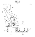
- Each of the boss axes 6, 6 has a peripheral surface consisting of a pair of flat surfaces 6a, 6a which are formed in parallel with the releasing direction 36 (see FIG.6) of the handle 2, and circular arc surfaces 6b, 6b which connect edges of the flat surfaces 6a, 6a respectively.
- the circular arc surfaces 6b, 6b constitute a part of one virtual circular peripheral surface 37 (see FIG.6).
- the bearing holes 7, 7 and grooves 8, 8 are formed in the upper and lower end walls 2a, 2b of the handle 2 respectively.
- Each of the bearing holes 7, 7 is partitioned by a partial inner peripheral surface 7a.
- the partial inner peripheral surface 7a has an inner diameter which is substantially equal to an outer diameter of the virtual circular peripheral surface 37.
- the groove 8 extends from the bearing hole 7 in the opposite direction to the operating portion 2d to open the bearing hole 7.
- the groove 8 is partitioned by a pair of inner surfaces 8a, 8b which are opposed in parallel with each other.
- a distance between the inner surfaces 8a, 8b is set slightly larger than a distance between the flat surfaces 6a, 6a of the boss axis 6. Therefore, when the flat surfaces 6a, 6a are positioned in almost parallel with the inner surfaces 8a, 8b, the boss axis 6 can be moved relatively along the groove 8.
- the boss axis 6 can be inserted/released into/from the bearing hole 7 by moving the boss axis 6 relatively along the groove 8 to thus attach/detach the handle 2 to/from the base 1.
- Both the circular arc surfaces 6b, 6b of the boss axis 6 come into contact with the partial inner peripheral surface 7a of the bearing hole 7 between the latching position P1 and the unlatching position P2. Only one of the circular arc surfaces 6b, 6b comes into contact with the partial inner peripheral surface 7a in the releasing position P3.
- the flat surfaces 6a, 6a of the boss axis 6 are tilted from the vertical direction 39 of the base plate 2a to the side which is opposite to the extending direction 38 of the operating portion 2d positioned in the latching position P1.
- the flat surfaces 6a, 6a are tilted relative to a center line 40 of the groove 8 in the latching position P1 such that the releasing direction 36 of the handle 2 in the releasing position P3 is positioned on the opposite side to the operating portion 2d positioned in the latching position P1.
- each of the contact areas between the circular arc surfaces 6b, 6b of the boss axis 6 in the unlatching position P2 and the partial inner peripheral surface 7a of the bearing hole 7 is set to exceed half (50 %) of a total area of the partial inner peripheral surface 7a.
- a projected portion 9 which extends in the radius-of-rotation direction of the handle 2 is provided to the upper end wall 2a of the handle 2.
- a protruded portion 10 which can engage with a lower surface 9a of the projected portion 9 in the unlatching position P2 is provided to the handle receiving portion 5 of the base 1.
- the inner surface 8a of the groove 8 which is positioned in the vicinity of an outer surface 2e of the handle 2 extends along the tangential direction of the partial inner peripheral surface 7a of the bearing hole 7.
- a second boss axis 11 having a second circular arc surface 11b is provided near a base end of the boss axis 6 which is formed in the lower wall 5b of the handle receiving portion 5.
- the second circular arc surface 11b has a larger radius of curvature than the circular arc surface 6b of the boss axis 6.
- a second bearing hole 12 and a second groove 13 which correspond to a second boss axis 11 are formed in the lower end wall 2b of the handle 2.
- the second groove 13 extends from the second bearing hole 12 to open the second bearing hole 12.
- the second bearing hole 12 is partitioned by a partial inner peripheral surface 12a having a radius of curvature which is substantially equal to that of the second circular arc surface 11b.
- the second groove 13 is partitioned by a pair of second inner surfaces 13a, 13b which are opposed to each other.
- the second inner surface 13a which is formed in the vicinity of the outer surface 2e of the handle 2 is formed coplanarly with the inner surface 8a of the groove 8.
- the second boss axis 11 opposes to the second inner surface 13a, and has a side wall 11a which is formed coplanarly with the flat surface 6a of the boss axis 6.
- An almost circular arc rib 14 which protrudes toward the lower wall 5b of the base 1 is provided to the lower end wall 2b of the handle 2. Since the rib 14 can come into contact with the lower wall 5b, play of the handle 2 can be suppressed in turning the handle 2.
- the handle 2 can be shifted between the latching position P1 and the unlatching position P2.
- the partial inner peripheral surface 7a of the bearing hole 7 comes into contact with both the circular arc surfaces 6b, 6b of the boss axis 6 and is supported by them, and also the partial inner peripheral surface 12a of the second bearing hole 12 comes into contact with the second circular arc surface 11b of the second boss axis 11 and is supported by it.
- a lock knob 15 in FIG.1 and a bumper rubber 16 in FIG.11 are fitted to the base 1.
- the bumper rubber 16 can contact the handle 2 to absorb the impact when the handle 2 is turned to the unlatching position P2 and then put back by the coil spring 3.
- One end of a rod 17 in FIG.11 is coupled to an end portion of the coupling portion 2c of the handle 2, and the other end of the rod 17 is coupled to a locking device (not shown).
- the rod 17 transmits an operation of the handle 2 to the locking device.
- a cover 18 in FIG.5 is secured to the base 1 to cover the inside of the base 1.
- An escutcheon 19 is attached to the base 1 to conceal a clearance between the cover 18 and a door trim 20.
- the flat surfaces 6a, 6a are tilted relative to the center line 40 of the groove 8 positioned in the latching position P1 such that the releasing direction 36 of the handle 2 in the releasing position P3 can be positioned on the opposite side of the operating portion 2d positioned in the latching position P1.
- the contact areas (overlapping lengths) between the circular arc surfaces 6b, 6b of the boss axis 6 in the unlatching position P2 and the partial inner peripheral surface 7a of the bearing hole 7 can be increased. Therefore, a surface pressure applied to the boss axis 6 of the base 1 can be reduced in the unlatching position P2 and thus the handle supporting strength can be improved.
- the projected portion 9 which can engage with the upper wall 5a in the unlatching position P2 is provided to the upper end wall 2a of the handle 2. For this reason, when the downward load is applied to the handle 2 in the unlatching position P2, the projected portion 9 engages with the upper wall 5a and is supported by it. Therefore, a downward inclination supporting strength in the axial direction of the handle 2 can be enhanced.
- the protruded portion 10 which can engage with the lower surface 9a of the projected portion 9 in the unlatching position P2 is provided to the handle receiving portion 5 of the base 1. For this reason, when the upward load is applied to the handle 2 in the unlatching position P2, the protruded portion 10 engages with the lower surface 9a of the projected portion 9 and is supported by it. Therefore, an upward inclination supporting strength in the axial direction of the handle 2 can be enhanced.
- the inner surface 8a of the groove 8 is formed on the tangent of the partial inner peripheral surface 7a of the bearing hole 7. For this reason, a thickness of the outer surface 2e side of the handle 2 can be suppressed to the lowest minimum, so that a clearance between the handle 2 and the base 1 can be reduced to the lowest minimum in fitting the handle 2. Therefore, the escutcheon 19 which is attached onto the outer periphery of the base after assembly can be reduced in size and also appearance after assembly can be improved.
- a coupling wall 41 between the upper end wall 2a and the lower end wall 2b of the handle 2 becomes close to the base 1 as it comes up to the lower end wall 2b.
- a size of the bearing hole 7 on the lower end wall 2b is limited, so that a diameter 42 of the boss axis 6 in the lower wall 5b becomes smaller than a diameter 43 of the boss axis 6 in the upper wall 5a.
- the second boss axis 11 is provided near the base end of the boss axis 6 in the lower wall 5b, and also the second bearing hole 12 into which the second boss axis 11 is inserted is provided to the lower end wall 2b of the handle 2.
- the partial inner peripheral surface 12a of the second bearing hole 12 can come into contact with the second circular arc surface 11b of the second boss axis 11 between the latching position P1 and the unlatching position P2 and can be supported by it. Hence, stress concentration caused in turning the handle 2 can be relaxed and thus a strength in the rotation direction can be improved.
- the second inner surface 13a of the second groove 13 which is formed in the vicinity of the outer surface 2e of the handle 2 is formed coplanarly with the inner surface 8a of the groove 8, and also the second boss axis 11 opposes to the second inner surface 13a and has the side wall 11a which is formed coplanarly with the flat surface 6a of the boss axis 6.
- the thickness of the outer surface 2e side of the handle 2 can be suppressed to the lowest minimum, so that the clearance between the handle 2 and the base 1 can be reduced to the lowest minimum in fitting the handle 2. Therefore, even if the second boss axis 11 is formed, a size of the escutcheon 19 can be reduced and also appearance after assembly can be improved.
Landscapes
- Lock And Its Accessories (AREA)
Abstract
Description
- The content of Application No.TOKUGANHEI 10-141577, filed on May 22, 1998 in Japan is hereby incorporated by reference.
- The present invention relates to a car inside handle unit structure.
- As an example of the related art, the car inside handle unit structure is set forth in Utility Model Application Publication (KOKOKU) Hei 6-7196.
- In the car inside handle unit structure in the related art, to increase an overlapping length between a bearing hole of a handle and boss axes of a base is limited. Therefore, in order to enhance a handle supporting strength of a base, change of material is needed, for example, costly polycarbonate material, etc. must be utilized.
- It is an object of the present invention to provide a car inside handle unit structure which is able to enhance the handle supporting strength without change of material.
- In order to achieve the above object, a car inside handle unit structure of the present invention comprises a handle, a base, an energizing member, and a stopper. The handle has a coupling portion and an operating portion extended from the coupling portion. The coupling portion has a pair of opposing end walls each of which has a bearing hole and a groove. The groove extends from the bearing hole in a direction opposite to the operating portion to open the bearing hole. The base is fixed to a car body and has a base plate and a pair of supporting walls which project from the base plate to oppose to each other. The supporting walls have a pair of boss axes which project from the supporting walls to oppose to each other. The boss axes are inserted into the bearing holes respectively to support the handle rotatably from a releasing position to a latching position via an unlatching position. The operating portion is positioned in substantially parallel with the base plate in the latching position, and stands upright in the base plate in the unlatching position. Each of the boss axes has an outer peripheral surface consisting of a pair of flat surfaces positioned in parallel and circular arc surfaces formed between the flat surfaces. Both the circular arc surfaces come into contact with a partial inner peripheral surface between the latching position and the unlatching position. When the handle is positioned in the releasing position, only one of the circular arc surfaces comes into contact with the partial inner peripheral surface of the bearing hole and also the flat surfaces allows the boss axis to pass through the groove. The boss axis is inserted/pulled out into/from the bearing hole through the groove. The flat surfaces being tilted from a vertical direction of the base plate to a side which is opposite to an extending direction of the operating portion positioned in the latching position. The energizing member is positioned to expand between the base and the handle, and energizes the handle toward the latching position. The stopper is fitted attachably/detachably to the base to prevent the handle from turning to the releasing position via the unlatching position.
- According to the above configuration, since the flat surfaces of the boss axes are tilted from the vertical direction of the base plate to the side which is opposite to the extending direction of the operating portion positioned in the latching position, contact areas between circular arc surfaces of the boss axes in the unlatching position and the partial inner peripheral surface of the bearing hole can be increased. Therefore, when the handle is positioned in the unlatching position, a surface pressure applied to the boss axes of the base can be reduced and thus the handle can be supported firmly.
-
- FIG.1 is an exploded perspective view showing a car inside handle unit structure according to an embodiment of the present invention;
- FIG.2 is a side view showing the car inside handle unit structure in FIG.1;
- FIG.3 is a sectional view, taken along a line 31-31 in FIG.2, showing the car inside handle unit structure positioned in an unlatching position;
- FIG.4 is a sectional view, taken along a line 32-32 in FIG.2, showing the car inside handle unit structure positioned in a latching position;
- FIG.5 is a sectional view, taken along a line 33-33 in FIG.2, showing the car inside handle unit structure positioned in a latching position;
- FIG.6 is a sectional view, taken along a line 34-34 in FIG.2, showing the car inside handle unit structure positioned in a state where a handle is removed;
- FIG.7 is a sectional view, taken along the line 34-34 in FIG.2, showing the car inside handle unit structure positioned in the unlatching position;
- FIG.8 is a sectional view, taken along the line 34-34 in FIG.2, showing the car inside handle unit structure positioned in the latching position;
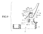
- FIG.9 is a sectional view, taken along a line 35-35 in FIG.2, showing the car inside handle unit structure positioned in a releasing position;
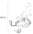
- FIG.10 is a sectional view, taken along the line 35-35 in FIG.2, showing the car inside handle unit structure positioned in the releasing position; and
- FIG.11 is a sectional view, taken along the line 35-35 in FIG.2, showing the car inside handle unit structure positioned in the latching position.
-
- A car inside handle unit structure according to an embodiment of the present invention will be explained with reference to the accompanying drawings hereinafter.
- As shown, a
base 1 which is secured onto a car body has a base plate 1a and ahandle receiving portion 5. A pair of walls, i.e., anupper wall 5a and alower wall 5b,which are provided in parallel so as to project from the base plate 1a as supporting walls, are provided to thehandle receiving portion 5.Boss axes upper wall 5a and thelower wall 5b respectively so as to oppose to each other. Ahandle 2 which is turned by an operator is inserted between theupper wall 5a and thelower wall 5b. - The
handle 2 consists of acoupling portion 2c which is partially contained in thehandle receiving portion 5 and anoperating portion 2d extending from thecoupling portion 2c. A pair of end walls, i.e., anupper end wall 2a and alower end wall 2b, which are provided in parallel so as to oppose to theupper wall 5a and thelower wall 5b respectively, are provided to thecoupling portion 2c. Bearingholes end walls end walls lower walls boss axes bearing holes handle 2 can be supported rotatably by theboss axes operating portion 2d is positioned in the latching position P1 in substantially parallel to the base plate 1a to expose anouter surface 2e of thehandle 2. As shown in FIG.7, theoperating portion 2d is separated from the base plate 1a in the unlatching position P2 to stand upright in the base plate 1a. - A
coil spring 3 serving as an energizing member is positioned to expand between thebase 1 and thehandle 2, and urges thehandle 2 toward the latching position P1. - A
stopper 4 can be fitted to thebase 1 attachably/detachably by latching apawl portion 4a. As indicated by a virtual line in FIG. 11, since a projectedend 21 of thecoupling portion 2c of thehandle 2 is engaged with thestopper 4, thehandle 2 can be prevented from moving to the releasing position P3 via the unlatching position P2. - Shifting of the
handle 2 to the releasing position P3 can be prevented by installing thestopper 4 onto thebase 1 after thehandle 2 has been fitted onto thebase 1, so that thehandle 2 can be prevented from being disconnected from thebase 1. - Each of the
boss axes flat surfaces handle 2, andcircular arc surfaces flat surfaces circular arc surfaces - The
bearing holes grooves lower end walls handle 2 respectively. Each of thebearing holes peripheral surface 7a. The partial innerperipheral surface 7a has an inner diameter which is substantially equal to an outer diameter of the virtual circularperipheral surface 37. When theboss axis 6 is inserted into thebearing holes peripheral surfaces circular arc surfaces - The
groove 8 extends from thebearing hole 7 in the opposite direction to theoperating portion 2d to open thebearing hole 7. Thegroove 8 is partitioned by a pair ofinner surfaces inner surfaces flat surfaces boss axis 6. Therefore, when theflat surfaces inner surfaces boss axis 6 can be moved relatively along thegroove 8. Theboss axis 6 can be inserted/released into/from thebearing hole 7 by moving theboss axis 6 relatively along thegroove 8 to thus attach/detach thehandle 2 to/from thebase 1. - Both the
circular arc surfaces boss axis 6 come into contact with the partial innerperipheral surface 7a of thebearing hole 7 between the latching position P1 and the unlatching position P2. Only one of thecircular arc surfaces peripheral surface 7a in the releasing position P3. - As shown in FIG.6, the
flat surfaces boss axis 6 are tilted from thevertical direction 39 of thebase plate 2a to the side which is opposite to the extendingdirection 38 of the operatingportion 2d positioned in the latching position P1. In other words, theflat surfaces center line 40 of thegroove 8 in the latching position P1 such that the releasingdirection 36 of thehandle 2 in the releasing position P3 is positioned on the opposite side to theoperating portion 2d positioned in the latching position P1. Therefore, as shown in FIG.7, contact areas (overlapping lengths) between thecircular arc surfaces boss axis 6 in the unlatching position P2 and the partial innerperipheral surface 7a of thebearing hole 7 can be increased. In this embodiment of the present invention, each of the contact areas between thecircular arc surfaces boss axis 6 in the unlatching position P2 and the partial innerperipheral surface 7a of thebearing hole 7 is set to exceed half (50 %) of a total area of the partial innerperipheral surface 7a. - A projected
portion 9 which extends in the radius-of-rotation direction of thehandle 2 is provided to theupper end wall 2a of thehandle 2. A protrudedportion 10 which can engage with alower surface 9a of the projectedportion 9 in the unlatching position P2 is provided to thehandle receiving portion 5 of thebase 1. - The
inner surface 8a of thegroove 8 which is positioned in the vicinity of anouter surface 2e of thehandle 2 extends along the tangential direction of the partial innerperipheral surface 7a of thebearing hole 7. - As shown in FIGS.1 and 9, a
second boss axis 11 having a secondcircular arc surface 11b is provided near a base end of theboss axis 6 which is formed in thelower wall 5b of thehandle receiving portion 5. The secondcircular arc surface 11b has a larger radius of curvature than thecircular arc surface 6b of theboss axis 6. Asecond bearing hole 12 and asecond groove 13 which correspond to asecond boss axis 11 are formed in thelower end wall 2b of thehandle 2. Thesecond groove 13 extends from thesecond bearing hole 12 to open thesecond bearing hole 12. Thesecond bearing hole 12 is partitioned by a partial innerperipheral surface 12a having a radius of curvature which is substantially equal to that of the secondcircular arc surface 11b. Thesecond groove 13 is partitioned by a pair of secondinner surfaces - As shown in FIG.9, the second
inner surface 13a which is formed in the vicinity of theouter surface 2e of thehandle 2 is formed coplanarly with theinner surface 8a of thegroove 8. As shown in FIG.10, thesecond boss axis 11 opposes to the secondinner surface 13a, and has aside wall 11a which is formed coplanarly with theflat surface 6a of theboss axis 6. - An almost
circular arc rib 14 which protrudes toward thelower wall 5b of thebase 1 is provided to thelower end wall 2b of thehandle 2. Since therib 14 can come into contact with thelower wall 5b, play of thehandle 2 can be suppressed in turning thehandle 2. - As shown in FIGS.6 and 9, when the
handle 2 is fitted to thebase 1, thestopper 4 is unlatched from thebase 1 and then thehandle 2 is shifted toward thebase 1 such that theboss axis 6 can be moved relatively along thegroove 8. At this time, thesecond boss axis 11 is moved relatively in thesecond groove 13. Accordingly, theboss axis 6 is inserted into thebearing hole 7 and also thesecond boss axis 11 is inserted into thesecond bearing hole 12. As a result, thehandle 2 can come to the releasing position P3 (see FIG.10) and thus it can be rotated upon theboss axis 6. Then, thehandle 2 is shifted from the releasing position P3 to the latching position P1 and then thestopper 4 is fitted onto thebase 1. Accordingly, thehandle 2 can be shifted between the latching position P1 and the unlatching position P2. Between the latching position P1 and the unlatching position P2, the partial innerperipheral surface 7a of thebearing hole 7 comes into contact with both thecircular arc surfaces boss axis 6 and is supported by them, and also the partial innerperipheral surface 12a of thesecond bearing hole 12 comes into contact with the secondcircular arc surface 11b of thesecond boss axis 11 and is supported by it. - A
lock knob 15 in FIG.1 and abumper rubber 16 in FIG.11 are fitted to thebase 1. Thebumper rubber 16 can contact thehandle 2 to absorb the impact when thehandle 2 is turned to the unlatching position P2 and then put back by thecoil spring 3. - One end of a
rod 17 in FIG.11 is coupled to an end portion of thecoupling portion 2c of thehandle 2, and the other end of therod 17 is coupled to a locking device (not shown). Therod 17 transmits an operation of thehandle 2 to the locking device. - A
cover 18 in FIG.5 is secured to thebase 1 to cover the inside of thebase 1. Anescutcheon 19 is attached to thebase 1 to conceal a clearance between thecover 18 and adoor trim 20. - As described above, in the present embodiment, the
flat surfaces center line 40 of thegroove 8 positioned in the latching position P1 such that the releasingdirection 36 of thehandle 2 in the releasing position P3 can be positioned on the opposite side of the operatingportion 2d positioned in the latching position P1. For this reason, the contact areas (overlapping lengths) between thecircular arc surfaces boss axis 6 in the unlatching position P2 and the partial innerperipheral surface 7a of thebearing hole 7 can be increased. Therefore, a surface pressure applied to theboss axis 6 of thebase 1 can be reduced in the unlatching position P2 and thus the handle supporting strength can be improved. - The projected
portion 9 which can engage with theupper wall 5a in the unlatching position P2 is provided to theupper end wall 2a of thehandle 2. For this reason, when the downward load is applied to thehandle 2 in the unlatching position P2, the projectedportion 9 engages with theupper wall 5a and is supported by it. Therefore, a downward inclination supporting strength in the axial direction of thehandle 2 can be enhanced. - The protruded
portion 10 which can engage with thelower surface 9a of the projectedportion 9 in the unlatching position P2 is provided to thehandle receiving portion 5 of thebase 1. For this reason, when the upward load is applied to thehandle 2 in the unlatching position P2, the protrudedportion 10 engages with thelower surface 9a of the projectedportion 9 and is supported by it. Therefore, an upward inclination supporting strength in the axial direction of thehandle 2 can be enhanced. - The
inner surface 8a of thegroove 8 is formed on the tangent of the partial innerperipheral surface 7a of thebearing hole 7. For this reason, a thickness of theouter surface 2e side of thehandle 2 can be suppressed to the lowest minimum, so that a clearance between thehandle 2 and thebase 1 can be reduced to the lowest minimum in fitting thehandle 2. Therefore, theescutcheon 19 which is attached onto the outer periphery of the base after assembly can be reduced in size and also appearance after assembly can be improved. - As shown in FIG.3, a coupling wall 41 between the
upper end wall 2a and thelower end wall 2b of thehandle 2 becomes close to thebase 1 as it comes up to thelower end wall 2b. For this reason, a size of thebearing hole 7 on thelower end wall 2b is limited, so that adiameter 42 of theboss axis 6 in thelower wall 5b becomes smaller than adiameter 43 of theboss axis 6 in theupper wall 5a. On the other hand, thesecond boss axis 11 is provided near the base end of theboss axis 6 in thelower wall 5b, and also thesecond bearing hole 12 into which thesecond boss axis 11 is inserted is provided to thelower end wall 2b of thehandle 2. Therefore, even if thediameter 42 of theboss axis 6 in thelower wall 5b is formed smaller than thediameter 43 of theboss axis 6 in theupper wall 5a, the partial innerperipheral surface 12a of thesecond bearing hole 12 can come into contact with the secondcircular arc surface 11b of thesecond boss axis 11 between the latching position P1 and the unlatching position P2 and can be supported by it. Hence, stress concentration caused in turning thehandle 2 can be relaxed and thus a strength in the rotation direction can be improved. - The second
inner surface 13a of thesecond groove 13 which is formed in the vicinity of theouter surface 2e of thehandle 2 is formed coplanarly with theinner surface 8a of thegroove 8, and also thesecond boss axis 11 opposes to the secondinner surface 13a and has theside wall 11a which is formed coplanarly with theflat surface 6a of theboss axis 6. For this reason, the thickness of theouter surface 2e side of thehandle 2 can be suppressed to the lowest minimum, so that the clearance between thehandle 2 and thebase 1 can be reduced to the lowest minimum in fitting thehandle 2. Therefore, even if thesecond boss axis 11 is formed, a size of theescutcheon 19 can be reduced and also appearance after assembly can be improved.
Claims (11)
- A handle unit structure comprising:a handle (2) having an operating portion (2d) extending from a coupling portion (2c) with a pair of opposing end walls (2a, 2b) each of which has a groove (8) extending from a bearing hole (7) in a direction opposite to the operating portion to open the bearing hole;a base (1) to be fixed to a car body, the body (1) having a pair of supporting walls (5a, 5b) which project from a base plate (la) and which oppose each other;a pair of boss axes (6) inserted into the respective bearing hole (7), the boss axes (6) projecting in opposition from the respective supporting walls (5a, 5b) to support the handle (2) so that it is rotatable from a releasing position to a latching position via an unlatching position, the operating portion (2d) being positioned substantially parallel with the base plate (1a) in the latching position and standing up from the base plate (1a) in the unlatching position, each boss axis (6) having an outer peripheral surface consisting of a pair of flat surfaces (6a) in parallel and circular arc surfaces (6b) between them, both the circular arc surfaces (6b) coming into contact with an inner peripheral surface (7a) of the bearing hole (7) from the latching position to the unlatching position, only one of the circular arc surfaces (6b) coming into contact with the said inner peripheral surface (7a) and the flat surfaces (6a) allowing the boss axis (6) to pass through the groove (8) when the handle (2) is positioned in the releasing position, the boss axis (6) being insertable into and removable from the bearing hole (7) through the groove (8), and the flat surfaces (6a) being tilted from a perpendicular to the base plate (1a) to a side which is opposite to the extending direction of the operating portion (2d) when positioned in the latching position;an energizing member (3), preferably a coil spring, arranged between the base (1) and the handle (2), the energizing member (3) urging the handle (2) toward the latching position; anda stopper (4) attached to the base (1), the stopper (4) preventing the handle (2) from turning to the releasing position via the unlatching position.
- The structure of claim 1, wherein at least one of the end walls (2a, 2b) has a projected portion which comes into contact with at least one of the supporting walls (5a, 5b) when the handle (2) is positioned in the unlatching position.
- The structure of claim 1 or 2, wherein one of the end walls (2a, 2b) has a projected portion which comes into contact with one of the supporting walls (5a, 5b) when the handle (2) is positioned in the unlatching position, and the other of the end walls (2a, 2b) has a protruded portion which comes into contact with the other of the supporting walls (5a, 5b) when the handle (2) is positioned in the unlatching position.
- The structure of any preceding claim, wherein the handle (2) has an outer surface which is exposed in the latching position, each groove (8) is defined by a pair of inner surfaces (8a, 8b) which are opposed to each other, and one of the inner surfaces, which is positioned in vicinity of the outer surface, extends along a tangential direction of the inner peripheral surface (7a) of the bearing hole (7).
- The structure of any preceding claim, wherein:one supporting wall (5b) has a second boss axis (11), the second boss axis (11) being near a base end of the first boss axis (6) and having a second circular arc surface (11b) which has a radius of curvature larger than the circular arc surfaces (6b) of the first boss axis (6);one end wall (2b) has a second bearing hole (12) which corresponds to the second boss axis (11); andthe second circular arc surface (11b) comes into contact with an inner peripheral surface (12a) of the second bearing hole (12) when the handle (2) is positioned in the unlatching position.
- The structure of claim 5, wherein:the handle (2) has an outer surface which is exposed in the latching position;the said one end wall (26) has a second groove (13) to open the second bearing hole (12);the second boss axis (11) is fitted into the second bearing hole (12) via the second groove (13) when the first boss axis (6) is inserted into the first bearing hole (7) via the first groove (8);the first and second grooves (8, 13) are defined by respective pairs of first and second inner surfaces (8a, 8b, 13a, 13b) which are opposed to each other;the first and second inner surfaces (8a, 13a) which are in vicinity of the outer surface are coplanar; andthe second boss axis (11) has a side surface (11a) which corresponds to the said second inner surface (13a) and is coplanar with one flat surface (6a) of the first boss axis (6).
- The structure of any preceding claim, wherein the flat surfaces (6a) are tilted from a perpendicular the base plate (1a) to a side which is opposite to the extending direction of the operating portion (2d) in the latching position, to such an extent that contact lengths between the circular arc surfaces (6b) of the boss axis (6) in the unlatching position and the inner peripheral surface (7a) of the bearing hole (7) can be increased.
- The structure of any preceding claim, wherein the base (1) has a handle receiving portion (5) with the supporting walls (5a, 5b), and at least part of the coupling portion (2c) is received in the handle receiving portion (5).
- The structure of any preceding claim, wherein the contact areas between the circular arc surfaces (6b) of the boss axis (6) and the inner peripheral surface (7a) of the bearing hole (7) exceed half the total area of the inner peripheral surface (7a) when the handle (2) is positioned in the unlatching position.
- The structure of any preceding claim, wherein each groove (8) is defined by a pair of inner surfaces (8a, 8b) which are opposed in parallel to each other, and the distance between the flat surfaces (6a) of the boss axes (6) is slightly larger than the distance between the inner surfaces (8a, 8b).
- A car inside handle unit structure comprising:wherein:a base (1) fixed to a car body, the base (1) having a pair of boss axes (6);a handle (2) rotatble upon the boss axes (6), one end of the handle (2) being supported to the base (1) via the boss axes (16) to be rotatable between a latching position and an unlatching position, the handle (2) being positioned substantially parallel with the base (1) in the latching position and standing up in the base (1) in the unlatching position;an energizing member (3) arranged between the base (1) and the handle (2), the energizing member (3) urging the handle (2) toward the latching position; anda stopper (4) attachably/detachably, fitted to the base, the stopper (4) preventing the handle (4) from turning to a releasing position via the unlatching position;the base (1) has a handle receiving portion (5) with a pair of supporting walls (5a, 5b),the handle receiving portion (5) receives the said one end of the handle (2), the boss axes (6) project from the supporting walls (5a, 5b) to oppose to each other, and each of the boss axes has an outer peripheral surface consisting of a pair of flat surfaces (6a) in parallel and circular arc surfaces (6b) to connect the flat surfaces,the handle (2) has a pair of end walls (2a, 2b) at the said one end, each of the end walls (2a, 2b) has a bearing hole (7) which engages with the boss axis (6) and a groove (8) through which the boss axis (6) is insertable into and removable from the bearing hole (7),the groove (8) extends from the bearing hole (7) to a side opposite to other end of the handle (2) to open the bearing hole (7), andthe flat surfaces (6a) are tilted relative to a center line of the groove (8) in the latching position such that the releasing direction of the handle (2) in the releasing position is positioned on an opposite side to other end of the handle (2) in the latching position, whereby contact lengths between the inner peripheral surface (7a) of the bearing hole (7) and the circular arc surfaces (6b) of the boss axis (6) in the unlatching position can be increased.
Applications Claiming Priority (2)
| Application Number | Priority Date | Filing Date | Title |
|---|---|---|---|
| JP14157798 | 1998-05-22 | ||
| JP14157798A JPH11336379A (en) | 1998-05-22 | 1998-05-22 | Inside handle unit structure of a car |
Publications (3)
| Publication Number | Publication Date |
|---|---|
| EP0959204A2 true EP0959204A2 (en) | 1999-11-24 |
| EP0959204A3 EP0959204A3 (en) | 2002-05-02 |
| EP0959204B1 EP0959204B1 (en) | 2004-07-21 |
Family
ID=15295230
Family Applications (1)
| Application Number | Title | Priority Date | Filing Date |
|---|---|---|---|
| EP19990303935 Expired - Lifetime EP0959204B1 (en) | 1998-05-22 | 1999-05-20 | Handle unit structure and car inside handle unit structure |
Country Status (4)
| Country | Link |
|---|---|
| US (1) | US6167779B1 (en) |
| EP (1) | EP0959204B1 (en) |
| JP (1) | JPH11336379A (en) |
| DE (1) | DE69918745T2 (en) |
Cited By (5)
| Publication number | Priority date | Publication date | Assignee | Title |
|---|---|---|---|---|
| WO2004067886A1 (en) * | 2003-01-29 | 2004-08-12 | Daimlerchrysler Ag | Outside door handle device |
| DE10123817B4 (en) * | 2000-05-16 | 2006-06-14 | Aisin Seiki K.K., Kariya | Vehicle door handle device |
| EP1722047A3 (en) * | 2005-05-13 | 2007-06-13 | Illinois Tool Works Inc. | Vehicle inside door handle |
| WO2012027265A1 (en) * | 2010-08-23 | 2012-03-01 | Illinois Tool Works Inc. | Snap set door handle and lock knob assembly |
| EP2947223A1 (en) * | 2014-05-22 | 2015-11-25 | Roto Frank Ag | Residential skylight tilting grip assembly, skylight with a skylight tilting grip assembly and method for mounting a skylight |
Families Citing this family (19)
| Publication number | Priority date | Publication date | Assignee | Title |
|---|---|---|---|---|
| FR2789426B1 (en) * | 1999-02-05 | 2001-06-15 | Valeo Securite Habitacle | MOTOR VEHICLE OPENING HANDLE |
| GB0020402D0 (en) * | 2000-08-19 | 2000-10-04 | Meritor Light Vehicle Sys Ltd | A handle arrangement |
| US6988752B2 (en) * | 2003-12-18 | 2006-01-24 | Illinois Tool Works Inc. | Pinless inside door handle assembly |
| US7036857B2 (en) * | 2003-12-22 | 2006-05-02 | Nissan Technical Center North America, Inc. | Vehicle inside door handle assembly |
| CA2566275C (en) * | 2004-06-23 | 2013-02-05 | Intier Automotive Closures Inc. | Structural door module |
| JP4453477B2 (en) * | 2004-08-05 | 2010-04-21 | アイシン精機株式会社 | Door handle device |
| EP1783305B1 (en) * | 2004-08-05 | 2015-04-22 | Aisin Seiki Kabushiki Kaisha | Door handle device |
| US20080018120A1 (en) * | 2006-07-18 | 2008-01-24 | Bailey Steve | Door Handle Assembly |
| JP4372780B2 (en) * | 2006-09-26 | 2009-11-25 | 本田技研工業株式会社 | Vehicle lock knob structure |
| US8091933B1 (en) * | 2007-09-21 | 2012-01-10 | Trimark Corporation | Heavy duty door latch and release modules |
| DE202008005128U1 (en) * | 2008-04-14 | 2008-07-10 | D. la Porte Söhne GmbH | Vehicle door lock with internal release lever |
| US9181733B2 (en) * | 2010-01-28 | 2015-11-10 | Kabushiki Kaisha Honda Lock | Vehicle door handle system |
| JP5633333B2 (en) * | 2010-11-25 | 2014-12-03 | アイシン精機株式会社 | Vehicle door inside handle |
| US8864193B2 (en) * | 2011-08-10 | 2014-10-21 | Honda Motor Co., Ltd. | Vehicle door inner handle cable connection |
| JP5783108B2 (en) * | 2012-03-28 | 2015-09-24 | アイシン精機株式会社 | Vehicle door handle device |
| JP5961478B2 (en) * | 2012-08-08 | 2016-08-02 | サカエ理研工業株式会社 | Vehicle door handle device |
| DE102016200589A1 (en) | 2015-02-05 | 2016-08-11 | Ford Global Technologies, Llc | The door handle assembly |
| US10550610B2 (en) * | 2016-06-22 | 2020-02-04 | Ford Global Technologies, Llc | Inside override emergency handle for door release |
| JP7457641B2 (en) * | 2020-12-23 | 2024-03-28 | 株式会社アルファ | inside handle device |
Citations (1)
| Publication number | Priority date | Publication date | Assignee | Title |
|---|---|---|---|---|
| JPH067196U (en) | 1992-06-29 | 1994-01-28 | 新日本無線株式会社 | Microwave heating device |
Family Cites Families (18)
| Publication number | Priority date | Publication date | Assignee | Title |
|---|---|---|---|---|
| US1602754A (en) * | 1922-07-04 | 1926-10-12 | Delbridge John Edward | Hinge |
| US2011675A (en) * | 1933-10-13 | 1935-08-20 | Richard L Cawood | Grinding mill door |
| US2555473A (en) * | 1946-04-11 | 1951-06-05 | Mcstay Jackson Co | Hinged container |
| US3424510A (en) * | 1967-06-05 | 1969-01-28 | Lakeside Mfg Inc | Display carts with bubble tops |
| US3471874A (en) * | 1967-12-22 | 1969-10-14 | American Standard Inc | Easily removed toilet seat |
| US3610460A (en) * | 1969-10-20 | 1971-10-05 | Marbelite Co | Traffic signal housing |
| JPS59126876A (en) * | 1982-12-30 | 1984-07-21 | アイシン精機株式会社 | Door handle apparatus of automobile |
| JPH067196Y2 (en) * | 1987-05-27 | 1994-02-23 | アイシン精機株式会社 | Inside door handle device |
| JPH0543169Y2 (en) * | 1988-09-19 | 1993-10-29 | ||
| US5038437A (en) * | 1990-10-26 | 1991-08-13 | Chrysler Corporation | Folding seat hinge assembly |
| JP3178089B2 (en) | 1992-06-25 | 2001-06-18 | 東レ株式会社 | Method for producing optically active mandelic acid |
| JP2603757Y2 (en) * | 1993-11-30 | 2000-03-21 | 富士機工株式会社 | Shifting device for automatic transmission |
| JP3319878B2 (en) * | 1994-06-15 | 2002-09-03 | サカエ理研工業株式会社 | Door handle device |
| DE29521920U1 (en) * | 1995-03-04 | 1998-10-22 | Kiekert AG, 42579 Heiligenhaus | Actuator for the door lock of a motor vehicle door |
| US5895081A (en) * | 1995-04-24 | 1999-04-20 | Aisin Seiki Kabushiki Kaisha | Inside door handle assembly for vehicles |
| JP3511730B2 (en) * | 1995-04-24 | 2004-03-29 | アイシン精機株式会社 | Vehicle door operating device |
| US5794994A (en) * | 1995-08-09 | 1998-08-18 | Ohi Seisakusho Co., Ltd. | Inside door handle unit for automotive vehicle |
| US6003204A (en) * | 1998-07-27 | 1999-12-21 | Deere & Company | Hood hinge mechanism |
-
1998
- 1998-05-22 JP JP14157798A patent/JPH11336379A/en active Pending
-
1999
- 1999-05-20 DE DE1999618745 patent/DE69918745T2/en not_active Expired - Fee Related
- 1999-05-20 EP EP19990303935 patent/EP0959204B1/en not_active Expired - Lifetime
- 1999-05-24 US US09/317,149 patent/US6167779B1/en not_active Expired - Fee Related
Patent Citations (1)
| Publication number | Priority date | Publication date | Assignee | Title |
|---|---|---|---|---|
| JPH067196U (en) | 1992-06-29 | 1994-01-28 | 新日本無線株式会社 | Microwave heating device |
Cited By (9)
| Publication number | Priority date | Publication date | Assignee | Title |
|---|---|---|---|---|
| DE10123817B4 (en) * | 2000-05-16 | 2006-06-14 | Aisin Seiki K.K., Kariya | Vehicle door handle device |
| WO2004067886A1 (en) * | 2003-01-29 | 2004-08-12 | Daimlerchrysler Ag | Outside door handle device |
| EP1722047A3 (en) * | 2005-05-13 | 2007-06-13 | Illinois Tool Works Inc. | Vehicle inside door handle |
| US7520543B2 (en) | 2005-05-13 | 2009-04-21 | Illinois Tool Works Inc. | Door handle assembly |
| US7527307B2 (en) | 2005-05-13 | 2009-05-05 | Illinois Tool Works Inc. | Door handle assembly |
| WO2012027265A1 (en) * | 2010-08-23 | 2012-03-01 | Illinois Tool Works Inc. | Snap set door handle and lock knob assembly |
| US10352072B2 (en) | 2010-08-23 | 2019-07-16 | Illinois Tool Works Inc. | Snap set door handle and lock knob assembly |
| EP2947223A1 (en) * | 2014-05-22 | 2015-11-25 | Roto Frank Ag | Residential skylight tilting grip assembly, skylight with a skylight tilting grip assembly and method for mounting a skylight |
| EP2947224A1 (en) * | 2014-05-22 | 2015-11-25 | Roto Frank Ag | Residential skylight tilting grip assembly, skylight with a skylight tilting grip assembly and method for mounting a skylight |
Also Published As
| Publication number | Publication date |
|---|---|
| EP0959204B1 (en) | 2004-07-21 |
| US6167779B1 (en) | 2001-01-02 |
| DE69918745T2 (en) | 2005-08-18 |
| DE69918745D1 (en) | 2004-08-26 |
| JPH11336379A (en) | 1999-12-07 |
| EP0959204A3 (en) | 2002-05-02 |
Similar Documents
| Publication | Publication Date | Title |
|---|---|---|
| EP0959204B1 (en) | Handle unit structure and car inside handle unit structure | |
| US6935601B2 (en) | Hook device | |
| KR100927295B1 (en) | Assist Grip Fastening Structure | |
| US6633347B2 (en) | Display assembly having display supported on casing to be controllable in attitude | |
| US6076233A (en) | Grab rail and hook assembly for a vehicle | |
| US20020104190A1 (en) | Child tether cover | |
| US6692067B2 (en) | Assist grip | |
| US6328384B1 (en) | Coupling structure between seatback and armrest for vehicle | |
| KR102382031B1 (en) | Handle device | |
| JP3737691B2 (en) | Accessories storage device | |
| JP2009006905A (en) | Shift lever device for automobile | |
| JP3474440B2 (en) | Inside handle unit structure of automobile | |
| JP2000296731A (en) | Device for fixing child seat to vehicle | |
| JPH1160166A (en) | Leg part structure of crane loaded on vehicle | |
| EP1046542A1 (en) | Handle assembly with integrated hook | |
| JP3468281B2 (en) | Car door outside handle device | |
| JP7457904B2 (en) | Mounting structure of functional parts | |
| JP3641943B2 (en) | Passenger seat table mounting structure for automotive instrument panels | |
| JP3391752B2 (en) | Caster mounting structure | |
| GB2299131A (en) | Key cylinder device | |
| CN222061920U (en) | Inner handle mounting assembly and vehicle | |
| JP7443893B2 (en) | Functional parts mounting structure | |
| JPH0720408Y2 (en) | Lock pin attachment | |
| JP4178352B2 (en) | Caster with swivel control mechanism | |
| JPH11100056A (en) | Stopper member of storing case |
Legal Events
| Date | Code | Title | Description |
|---|---|---|---|
| PUAI | Public reference made under article 153(3) epc to a published international application that has entered the european phase |
Free format text: ORIGINAL CODE: 0009012 |
|
| 17P | Request for examination filed |
Effective date: 19990615 |
|
| AK | Designated contracting states |
Kind code of ref document: A2 Designated state(s): AT BE CH CY DE DK ES FI FR GB GR IE IT LI LU MC NL PT SE Kind code of ref document: A2 Designated state(s): DE GB |
|
| AX | Request for extension of the european patent |
Free format text: AL;LT;LV;MK;RO;SI |
|
| PUAL | Search report despatched |
Free format text: ORIGINAL CODE: 0009013 |
|
| AK | Designated contracting states |
Kind code of ref document: A3 Designated state(s): AT BE CH CY DE DK ES FI FR GB GR IE IT LI LU MC NL PT SE |
|
| AX | Request for extension of the european patent |
Free format text: AL;LT;LV;MK;RO;SI |
|
| AKX | Designation fees paid |
Free format text: DE GB |
|
| 17Q | First examination report despatched |
Effective date: 20030303 |
|
| RTI1 | Title (correction) |
Free format text: HANDLE UNIT STRUCTURE AND CAR INSIDE HANDLE UNIT STRUCTURE |
|
| RTI1 | Title (correction) |
Free format text: HANDLE UNIT STRUCTURE AND CAR INSIDE HANDLE UNIT STRUCTURE |
|
| GRAP | Despatch of communication of intention to grant a patent |
Free format text: ORIGINAL CODE: EPIDOSNIGR1 |
|
| GRAS | Grant fee paid |
Free format text: ORIGINAL CODE: EPIDOSNIGR3 |
|
| GRAA | (expected) grant |
Free format text: ORIGINAL CODE: 0009210 |
|
| AK | Designated contracting states |
Kind code of ref document: B1 Designated state(s): DE GB |
|
| REG | Reference to a national code |
Ref country code: GB Ref legal event code: FG4D |
|
| REG | Reference to a national code |
Ref country code: IE Ref legal event code: FG4D |
|
| REF | Corresponds to: |
Ref document number: 69918745 Country of ref document: DE Date of ref document: 20040826 Kind code of ref document: P |
|
| PLBE | No opposition filed within time limit |
Free format text: ORIGINAL CODE: 0009261 |
|
| STAA | Information on the status of an ep patent application or granted ep patent |
Free format text: STATUS: NO OPPOSITION FILED WITHIN TIME LIMIT |
|
| 26N | No opposition filed |
Effective date: 20050422 |
|
| PGFP | Annual fee paid to national office [announced via postgrant information from national office to epo] |
Ref country code: DE Payment date: 20080529 Year of fee payment: 10 |
|
| PGFP | Annual fee paid to national office [announced via postgrant information from national office to epo] |
Ref country code: GB Payment date: 20080521 Year of fee payment: 10 |
|
| GBPC | Gb: european patent ceased through non-payment of renewal fee |
Effective date: 20090520 |
|
| PG25 | Lapsed in a contracting state [announced via postgrant information from national office to epo] |
Ref country code: GB Free format text: LAPSE BECAUSE OF NON-PAYMENT OF DUE FEES Effective date: 20090520 |
|
| PG25 | Lapsed in a contracting state [announced via postgrant information from national office to epo] |
Ref country code: DE Free format text: LAPSE BECAUSE OF NON-PAYMENT OF DUE FEES Effective date: 20091201 |