EP0959014B1 - Container latch operable from the front - Google Patents
Container latch operable from the front Download PDFInfo
- Publication number
- EP0959014B1 EP0959014B1 EP99110017A EP99110017A EP0959014B1 EP 0959014 B1 EP0959014 B1 EP 0959014B1 EP 99110017 A EP99110017 A EP 99110017A EP 99110017 A EP99110017 A EP 99110017A EP 0959014 B1 EP0959014 B1 EP 0959014B1
- Authority
- EP
- European Patent Office
- Prior art keywords
- latch
- lever
- hook
- pin
- spring
- Prior art date
- Legal status (The legal status is an assumption and is not a legal conclusion. Google has not performed a legal analysis and makes no representation as to the accuracy of the status listed.)
- Expired - Lifetime
Links
- 230000003068 static effect Effects 0.000 claims description 4
- 230000007774 longterm Effects 0.000 claims description 2
- 230000001419 dependent effect Effects 0.000 claims 2
- 239000000463 material Substances 0.000 abstract description 12
- 239000004033 plastic Substances 0.000 abstract description 12
- 238000010276 construction Methods 0.000 abstract description 3
- 238000013461 design Methods 0.000 abstract description 2
- 230000008901 benefit Effects 0.000 description 8
- 230000009471 action Effects 0.000 description 3
- 239000012530 fluid Substances 0.000 description 3
- 230000007246 mechanism Effects 0.000 description 3
- 229910052751 metal Inorganic materials 0.000 description 3
- 239000002184 metal Substances 0.000 description 3
- 238000012552 review Methods 0.000 description 3
- 238000004891 communication Methods 0.000 description 2
- 230000000881 depressing effect Effects 0.000 description 2
- 229920000728 polyester Polymers 0.000 description 2
- 229920001169 thermoplastic Polymers 0.000 description 2
- 239000004416 thermosoftening plastic Substances 0.000 description 2
- SYJPAKDNFZLSMV-HYXAFXHYSA-N (Z)-2-methylpropanal oxime Chemical compound CC(C)\C=N/O SYJPAKDNFZLSMV-HYXAFXHYSA-N 0.000 description 1
- 229910000639 Spring steel Inorganic materials 0.000 description 1
- 229910052782 aluminium Inorganic materials 0.000 description 1
- XAGFODPZIPBFFR-UHFFFAOYSA-N aluminium Chemical compound [Al] XAGFODPZIPBFFR-UHFFFAOYSA-N 0.000 description 1
- 230000003247 decreasing effect Effects 0.000 description 1
- 230000007812 deficiency Effects 0.000 description 1
- 230000009977 dual effect Effects 0.000 description 1
- 230000005484 gravity Effects 0.000 description 1
- 239000000314 lubricant Substances 0.000 description 1
- 238000000034 method Methods 0.000 description 1
- 238000012986 modification Methods 0.000 description 1
- 230000004048 modification Effects 0.000 description 1
- 230000000135 prohibitive effect Effects 0.000 description 1
- 230000009467 reduction Effects 0.000 description 1
- 238000006467 substitution reaction Methods 0.000 description 1
- 230000002459 sustained effect Effects 0.000 description 1
- 230000000007 visual effect Effects 0.000 description 1
Images







Classifications
-
- B—PERFORMING OPERATIONS; TRANSPORTING
- B65—CONVEYING; PACKING; STORING; HANDLING THIN OR FILAMENTARY MATERIAL
- B65D—CONTAINERS FOR STORAGE OR TRANSPORT OF ARTICLES OR MATERIALS, e.g. BAGS, BARRELS, BOTTLES, BOXES, CANS, CARTONS, CRATES, DRUMS, JARS, TANKS, HOPPERS, FORWARDING CONTAINERS; ACCESSORIES, CLOSURES, OR FITTINGS THEREFOR; PACKAGING ELEMENTS; PACKAGES
- B65D45/00—Clamping or other pressure-applying devices for securing or retaining closure members
- B65D45/02—Clamping or other pressure-applying devices for securing or retaining closure members for applying axial pressure to engage closure with sealing surface
- B65D45/16—Clips, hooks, or clamps which are removable, or which remain connected either with the closure or with the container when the container is open, e.g. C-shaped
- B65D45/20—Clips, hooks, or clamps which are removable, or which remain connected either with the closure or with the container when the container is open, e.g. C-shaped pivoted
- B65D45/24—Clips, hooks, or clamps which are removable, or which remain connected either with the closure or with the container when the container is open, e.g. C-shaped pivoted incorporating pressure-applying means, e.g. screws or toggles
-
- Y—GENERAL TAGGING OF NEW TECHNOLOGICAL DEVELOPMENTS; GENERAL TAGGING OF CROSS-SECTIONAL TECHNOLOGIES SPANNING OVER SEVERAL SECTIONS OF THE IPC; TECHNICAL SUBJECTS COVERED BY FORMER USPC CROSS-REFERENCE ART COLLECTIONS [XRACs] AND DIGESTS
- Y10—TECHNICAL SUBJECTS COVERED BY FORMER USPC
- Y10T—TECHNICAL SUBJECTS COVERED BY FORMER US CLASSIFICATION
- Y10T292/00—Closure fasteners
- Y10T292/08—Bolts
- Y10T292/0911—Hooked end
-
- Y—GENERAL TAGGING OF NEW TECHNOLOGICAL DEVELOPMENTS; GENERAL TAGGING OF CROSS-SECTIONAL TECHNOLOGIES SPANNING OVER SEVERAL SECTIONS OF THE IPC; TECHNICAL SUBJECTS COVERED BY FORMER USPC CROSS-REFERENCE ART COLLECTIONS [XRACs] AND DIGESTS
- Y10—TECHNICAL SUBJECTS COVERED BY FORMER USPC
- Y10T—TECHNICAL SUBJECTS COVERED BY FORMER US CLASSIFICATION
- Y10T292/00—Closure fasteners
- Y10T292/08—Bolts
- Y10T292/0911—Hooked end
- Y10T292/0913—Sliding and swinging
- Y10T292/0914—Operating means
- Y10T292/0917—Lever
-
- Y—GENERAL TAGGING OF NEW TECHNOLOGICAL DEVELOPMENTS; GENERAL TAGGING OF CROSS-SECTIONAL TECHNOLOGIES SPANNING OVER SEVERAL SECTIONS OF THE IPC; TECHNICAL SUBJECTS COVERED BY FORMER USPC CROSS-REFERENCE ART COLLECTIONS [XRACs] AND DIGESTS
- Y10—TECHNICAL SUBJECTS COVERED BY FORMER USPC
- Y10T—TECHNICAL SUBJECTS COVERED BY FORMER US CLASSIFICATION
- Y10T292/00—Closure fasteners
- Y10T292/08—Bolts
- Y10T292/0911—Hooked end
- Y10T292/0945—Operating means
- Y10T292/0946—Link and lever
-
- Y—GENERAL TAGGING OF NEW TECHNOLOGICAL DEVELOPMENTS; GENERAL TAGGING OF CROSS-SECTIONAL TECHNOLOGIES SPANNING OVER SEVERAL SECTIONS OF THE IPC; TECHNICAL SUBJECTS COVERED BY FORMER USPC CROSS-REFERENCE ART COLLECTIONS [XRACs] AND DIGESTS
- Y10—TECHNICAL SUBJECTS COVERED BY FORMER USPC
- Y10T—TECHNICAL SUBJECTS COVERED BY FORMER US CLASSIFICATION
- Y10T292/00—Closure fasteners
- Y10T292/08—Bolts
- Y10T292/0911—Hooked end
- Y10T292/0945—Operating means
- Y10T292/0949—Lever
Definitions
- the invention relates to latches. More particularly, the invention relates to latches which are engageable and disenageable from an easily accessible area to an otherwise inaccessible area such as when a latch is actuatable from a front of a container and the latch hook is on the side of the container, the side of the container being obscured by other containers.
- front opening latches since the first surface perceived by a user is considered to be the "front" of the container.
- front is used generically to indicate the exposed surface of the container. This could actually be, however, any surface of the container.
- Front opening latches of the prior art have been developed for the same purpose as the present invention; that is to allow operation of the latch where containers are stacked next to one another obstructing access to the sides of the container. Since other conventional latches reside on the side of the container or require movement out of the plane of the side of the container, operation of these would be severely impeded.
- Two main categories of prior art latches are intended to satisfy the desire/requirement for front operation latches. These are 1) side mounted latches that are operable when access to box sides is limited and 2) top mounted latches.
- FIGURE 1 of this application an example of an arguably “front only” actuatable latch is known by the trade name “Hook Lock” and is illustrated in FIGURE 1 of this application.
- the latch incorporates a cam design so that movement of the handle lever causes both an arcuate and a radial movement of the hook.
- the hook moves into engagement with the keeper plate.
- Further movement of the lever in the same direction causes the hook to draw the keeper plate toward the cam of the handle lever. This action draws the container cover toward its base and provides a tight closure.
- the latch is sold as actuatable from the front only because if mounted in a recess in the container side, it is considered possible to slide one's finger between adjacent containers and actuate the latch without actually seeing more than the end of the lever. Clearly, this suffers the substantial drawback that the latch could not be actuated in this manner if the cover of the container was deep. If it were, the fingers of the user would not reach the latch. Thus, this type of latch is not a viable solution to the front only operation dilemma.
- Top mounted latches provide more diversity in the front only operation forum since they truly operate from the exposed surface of the container.
- Prior art top mounted latches have certain inherent drawbacks with some types of containers (e.g., fluid tight containers).
- top mounting latch is a bail spring latch such as that illustrated in FIGURE 2 of the disclosure.
- This type of latch although effective in closing and tensioning a container lid, requires a "through the container" mounting.
- these latches require a very effetive (expensive) dynamic seal. Dynamic seals of this nature are cost prohibitive, subject to failure and therefore do not provide a preferred solution.
- a latch according to the preamble of claim 1 is described in FR 1578189.
- This latch comprises a latch base, a hook, a latch lever articulated with said hook at an articulation point, a lever pin articulating said latch lever with said latch base and a hook pin associated with said articulation point.
- front is employed in this specification as the location of operability of the latch disclosed herein, it will be understood that any plane of the container on which the latch is employed could be the operation plane or surface. More specifically, the latch body could be mounted on the front, top, side, bottom or rear of the container depending upon how the container is being viewed.
- the more important concept of the invention is that the latch is completely operable from an exposed plane or surface of the container, while acting on an adjacent surface which may be obscured from access or view. This is particularly advantageous when said containers are stacked one atop another or next to one another, etc. The most ubiquitous example of such use is, of course, where many of such containers are stacked in such a way that they create a wall.
- An important feature of the invention is variability in the available stroke for drawdown. By varying the distance between certain components of the invention the stroke is increased or decreased. This benefit is achieved while not affecting the motion of the hook perpendicular to the side of the container. In other words the attachment of the hook to the latch lever, discussed hereunder in detail, does not need to move laterally during drawdown regardless of the stroke of the latch. This concept cannot be achieved by the prior art and provides a significant advantage in function.
- the latch is preferably made of thermoplastic polyester which would creep under loads normally associated with latches intended to secure covers to containers as is the current invention.
- the surface area of load bearing components of the latch have been enlarged to enable sufficient strength of the inexpensive and relatively malleable material to be employed.
- the latch of the invention generally comprises a latch body having several components mounted as a unit on one surface of a container and a hook that is disposed generally perpendicularly to the latch body and is selectively engageable with a strike mounted fixedly on a surface of the container adjacent the surface upon which the body is mounted.
- the latch operates over the generally perpendicular angle by facilitating control of the hook from a spring lever disposed on or in the body.
- the latch develops about 445 N (100 lbf) of closure force near the end of its stroke and securely holds the cover of the container in place and sealed. Operation force required by the user, however, remains very small at 44.5 N (10 lbf ) or less.
- the latch is maintained in the closed position by either or both of an over-center pivot point arrangement relative to the principal drawdown force vector of the draw down assembly and a hold down catch in the latch body.
- Another feature of the latch of the invention is a warning system indicating that the latch is not engaged. Since it is desirable to prevent the latch lever from being freely located beyond the outer plane of a container to which it is mounted (i.e., mounted in a recess), it is spring loaded to return to and stay in the down or closed position when it is disengaged. Since in this position the latch appears to be engaged it is advantageous in the preferred embodiment to provide a system to warn a user that the latch is not, in fact, engaged. This is provided by a movement within the body of the latch allowing a colored section to be visible if the latch is not engaged. This colored section is not visible when the latch is engaged.
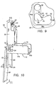
- FIGURES 3 and 6 the invention is illustrated in the engaged position. It will be appreciated from a review of these figures that the latch of the invention maintains all components on the exterior of the container to which it is attached, thereby requiring no dynamic seals. This is of great benefit to maintain the fluid tightness often required of the type of container for which the latch was developed. Additionally, this is a significant advance over prior art systems with respect to reliability and economy.
- Latch body 10 comprises base 12 with bosses 14a and 14b for receiving screws from within container 16 to attach latch body 10 thereto. It should also be noted that upon boss 14b a catch 18 is located to receive a similar feature on the latch lever discussed hereunder. Catch 18 provides assurance that latch lever 30 stays in the closed position even under the forces (e.g., gravity, impact with other structures, etc.) sustained during the impact of a drop of for example of 25.4-50.8 cm (10 - 20 inches) by careless personnel or due to perhaps a stack of containers falling over.
- forces e.g., gravity, impact with other structures, etc.
- Base 12 further includes trap support 19 and trap 22.
- Trap support 19 is preferably a continuation of base 12 which extends over the edge of the plane upon which base 12 is supported. Trap support 19 functions to provide trap 22 which is desirable in a preferred embodiment to prevent the hook from moving more than necessary to clear the strike and to stay within the recess thereby not breaking the plane of the surface of the container.
- trap support 19 further includes an extension 20 perpendicularly oriented thereto.
- Extension 20 includes a tang 24 which is dimensioned to be received in a depression 26 (see FIGURE 6) of the container 16 to provide further restraint for the trap 22.
- a container must be specifically manufactured to be fitted with this latch. The embodiment is preferred due to the superior strength thereof without the use of additional fasteners.
- the latch of the invention can be constructed without extension 20 so as to be employable as a retrofit on containers which have not been specifically designed for use with front opening latches of the invention having extension 20.
- latch lever 30 in operable communication with base 12 of latch body 20 is latch lever 30.
- latch lever 30 is nested within uprights 13 of base 12.
- Lever 30 is required to articulate with base 12 to operate the mechanism of the invention.
- the articulation of lever 30 with base 12 is through an L-shaped groove 36 in base 12 and a dual pin system.
- the two pin structures 32 and 34 in communication with the base 12, are designed to move in the L-shaped groove 36 to facilitate the desired movement of the various components of the invention (The terms pin structures are used here because there are actually two parts of each pin, the pin does not extend all the way across the latch. Hereafter the singular term pin will be employed for simplicity).
- pin 32 is a part of hook 38 (actually hook 38 splits at its upper extreme to form two hoops 38a and b to which the pins 32 are attached) and that movement of this pin causes the hook to move through its stroke. Since the desired movement of the hook 38 is substantially parallel to the principal force vector encountered in closing the container on which the latch is mounted, the section 36a of L-shaped groove 36 where hook pin 32 moves is also parallel to that principal force vector. Hook pin 32 is mounted in recess 31 of latch lever 30 so that lever 30 may rotate therearound and hook pin 32 transfers draw down force through the lever 30 to the cam surface 33 and then to base 12.
- hook pin 32 is mounted in such a way as to tend to keep the latch lever 30 closed. More specifically, hook pin 32 is mounted in recess 31 in lever 30 in a position allowing it to be just over-center of the cam surface 33 when the latch is in the closed position. This tends to maintain the latch in the closed position.
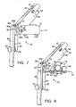
- latch pin 34 has an unusual shape. The shape is important to operation of a preferred embodiment because it provides movement in desired directions only. Importantly, latch pin 34 having a generally triangular appearance facilitates features of the invention such as a latch open flag, positive return of the lever 30 to the closed position and urging of the hook downwardly for engagement or disengagement with the strike. From a review of FIGURES 8 and 9, one of ordinary skill in the art will note that angled surface 35 of latch pin 34, which is preferably about 45° to an imaginary horizontal reference in the drawing, never moves off inside radius 37 ofL-shape 36 when the latch lever 30 is in the closed position and the hook is not engaged.
- latch pin 34 is offset relative to hook pin 32 in order to provide a sufficient length of surface 35 to prevent that surface from moving off radius 37.
- additional space must be provided. If the space of area 45 is not provided, tip 41 would contact the top and bottom walls of groove section 36b simultaneously and would prevent lever 30 from being fully raised.
- Enlarged area 45 is of a shape complimentary to tip 41 of latch pin 34 so that these parts may easily fit into the enlarged area. Because area 45 allows latch pin 34 to rotate 90° in groove 36, lever 30 is rotatable to the fully raised position. Tip 41 bears on radius 47 of area 45 to provide downward leverage to hook pin 32 through lever 30.
- the hook is therefore urged downwardly toward the end of its stroke when latch pin 34 is in area 45.
- a benefit is achieved by the arrangement of the latch lever in the base of the invention in that very little actuation force (less than 44.5 N (10 lbf), loaded) relative to the drawdown force ( approximately 445 N (100 lbf)) is needed to open or close the latch when loaded.
- very little actuation force less than 44.5 N (10 lbf), loaded
- the drawdown force approximately 445 N (100 lbf)
- the latch of the invention substantially avoids perpendicular movement relative to the principal force vector of closure.
- perpendicular movement relative to the principal force vector it is assumed that firstly that one of ordinary skill in the art will appreciate that there is a principal force vector in a latch mechanism; secondly that the principal force vector existing in the latch of the invention will be along the hook since it is designed to be there and based upon the operation of components, that is where it in fact is; and thirdly that perpendicular movement relative to a vector, includes any movement having a perpendicular component to its movement.
- the pin 32 necessarily must move in the principal force vector but that it must move in a direction substantially parallel with that vector.
- the parallel movement may be within the vector but also may be outside the vector.
- hook pin 32 By moving lever 30 to the raised position the hook pin 32 is allowed (and urged against the bias of spring 58 by continued upward movement of lever 30) to move toward the strike 39 causing the loading force of hook 38 against strike 39 to be released.
- hook pin 32 is moved away from strike 39 with hook 38 catching strike 39.
- the draw down force created hereby is transmitted to the container cover and compresses a seal (not shown) on the parting line securing the cover to the base of the container.
- the mechanism of movement of the pin 32 toward strike 39 in the present invention provides the additional benefit of variability in the stroke of the hook 38.
- lever 30 is maintained in the "down" position, redundantly, whether engaged or disengaged, by detent 40 which is preferably a downstruck projection from a center section of the latch lever 30 and positioned to align lip 42 of detent 40 with catch 18 of boss 14b.
- detent 40 which is preferably a downstruck projection from a center section of the latch lever 30 and positioned to align lip 42 of detent 40 with catch 18 of boss 14b.
- button 44 is provided by severing the surface material of latch lever 30 on three sides to create a cantilevered portion that is easily deflected by placing pressure on the end thereof Deflection ease of button 44 is assisted by chamfer 61 on lever 30 to permit a user's finger more room to deflect button 44.
- Spring 58 is located and secured in base 12 and provides cantilever spring tongue 59 to interact with other components as discussed hereunder.
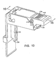
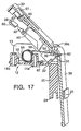
- Spring 58 includes feet 63 (see FIGURES 5and 17) at the ends of legs 65 which are provided to secure the spring. Feet 63 are adapted to fit within blocks 67 while legs are placed under leg holders 69. It will be appreciated that these features are well illustrated on one side of the latch in FIGURE 8, however the features are identically provided on the other side of the latch in a preferred embodiment. By employing a single spring for all functions, complexity, cost and assembly time are reduced. To understand operation of spring 58, spring lever 50 must first be introduced.
- Spring lever 50 is preferably nested in latch lever 30 and pivotally mounted therein on spring pivot pins 52.
- the pivot action of lever 50 facilitates one finger deflection of cantilever spring tongue 59 by depressing trigger surface 56. Movement of spring tongue 59 is caused by spring tongue cam 54 bearing thereupon occasioned by actuation of trigger 56 (and by raising latch lever 30). The movement imparted to spring tongue 59 by tongue cam 54, causes it to bear against landing 60 on or in hook 38. (It should be noted that landing 60 can be created by opening a hole in hook 38 (as illustrated) or by providing a projection from the rear surface thereof at an appropriate location to intersect with spring tongue 59.
- Reengagement of the latch of the invention is a simple one hand operation.
- Lever 30 is raised to the upright position and trigger 56 is actuated. These two actions cause hook 38 to be urged into a position where it is aligned with strike 39.
- Lever 30 is then moved back to the closed position while holding trigger 56 and hook and strike engage and provide draw down force to the cover of container 16.
- approximately 445 N (100 lbf) of draw down force is developed in hook 38 and detent 40 snaps lip 42 into engagement with catch 18 of boss 14b.
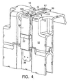
- pin 32 In a preferred embodiment of the invention the exact placement of pin 32, size and shape of pin 34 as discussed and the length of groove 36 is important for a safety feature. Since the latch lever is always biased into the closed position it would be difficult to know if the container was indeed latched shut without checking each of the latches. Visually checking the hook and strike of the latches can be extremely difficult in a wall of containers for the same reasons front operation latches are needed. To alleviate this time consuming, 5 difficult, and often inconclusive procedure, the inventor hereof has devised a warning system as follows and is illustrated in FIGURE 4: By allowing room at the top of groove 36, pin 32 is permitted to move high enough to allow latch lever 30 to become slightly unnested in base 12.
- Pin 34 also moves up groove 36 but as previously stated never moves beyond radius 47.
- Lever 30 moves upwardly from base 12 approximately 0.3 cm (1/8 th inch) by the natural bias of spring 58 when hook 38 is disengaged from strike 39.
- a brightly colored surface 70 on each side of latch lever 30 that is only visible when the latch lever has been elevated by the 0,3 cm (1/8 th inch) due to the hook 38 not being engaged, a quick visual check of the latch will immediately inform the user as to the condition of the latch.
- the brightly colored surfaces are completely concealed by upright members 13 of base 12.
- cam surface 33 is made up of preferably four force bearing surfaces 33 a-d. These surfaces distribute the static closure force of the latch.
- the surface area to be provided is selected so that with a static closure force of 133 N (60 lbs), the compressive stress is less than 3.5 ⁇ 10 6 Pa (500 psi) and the long term strain at the maximum operating temperature will be less than 2 %.
- the arrangement enables the latch lever cam surface 33 to withstand extended use without significant creep(causing failure or reduction of efficiency).
- Another area of concentration of forces on a plastic surface is at recess 31.
- the recesses are each dimensioned to achieve a large surface area to spread the forces experienced.
- pin 32 of hook 38 is significantly larger than it might be if the latch was constructed of metal.
- finger rest protuberances 29 which act both to strengthen the latch lever 30 and to provide comfort to the user.
- the latch of the invention can certainly be constructed of material other than plastic (e.g. metal) and may employ surface areas for bearing loads which are below those preferred herein for the use of plastic. This is due to the inherent structural rigidity of metal and should be appreciated by one of skill in this art.
- button 144 is visible.
- Button 144 replaces button 44 in the previous embodiment.
- Button 144 includes downstruck member 140 with lip 142 to engage catch 118 on boss 114b.
- Button 144 is articulated within latch lever 130 on pin 170 in boss 172 on either side of latch lever 130.
- Button 144 and member 140 are together actuable by depressing button 144 downwardly against spring 174 to disengage lip 142 from catch 118.
- Button 144 further includes stop 176 to maintain button 144 in the appropriate position when lip 142 is not engaged with catch 118.
- button 144 includes ridges 178 for a sure grip.
- This embodiment is identical in all other respects with the previous embodiment except for the extension and tang of the prior embodiment.
Landscapes
- Engineering & Computer Science (AREA)
- Mechanical Engineering (AREA)
- Closures For Containers (AREA)
- Air Bags (AREA)
- Lock And Its Accessories (AREA)
Abstract
Description
Claims (18)
- A latch comprising:characterized in thata latch base (12) adapted to be disposed on a first plane;a hook (38), selectively engageable with a separate structure and adapted to extend along a second plane, said second plane being substantially perpendicular to said first plane;a latch lever (30) articulated with said hook (38) at an articulation point;a lever pin (34) connected to said latch lever (30) articulating said latch lever (30) with said latch base (12); anda hook pin (32) connected to said hook (38) and associated with said articulation point;said latch base (12) comprises a bottom and at least one protrusion (13) substantially perpendicular to said bottom;an L-shaped groove (36) is formed in said protrusion (13), said L-shaped groove (36) including a first portion (36b) substantially parallel to said first plane, a second portion (36a) substantially parallel to said second plane and an inside radius portion (37) therebetween;said lever pin (34) and said hook pin (32) are moveable in said L-shaped groove (36) in such a way that said lever pin (34) moves across said inside radius portion (37) and within said first portion (36b) and said hook pin (32) moves within said second portion (36a);a spring lever (50) is articulated within said latch lever (30); anda spring (58) is mounted in said latch base (12) and operably in contact with said spring lever (50) and said hook (38), whereby actuation of said spring lever (50) and said latch lever (30) causes movement of said hook (38).
- A latch as claimed in claim 1, wherein said latch further comprisesa strike (39) attachable to said separate structure, said strike (39) being selectively engageable by said hook (38).
- A latch as claimed in claim 2, wherein said base (12) comprises at least two L-shaped grooves (36) on either side thereof to provide articulated engagement of said latch lever (30).
- A latch as claimed in claim 2 or 3, wherein said latch further comprises:a detent (40) having a lip (42) connected to said latch lever (30); anda catch (18) disposed on said latch base (12) whereby when said detent (40) and said catch (18) are engaged the latch is maintained in a closed position.
- A latch as claimed in claim 3 or 4, wherein said latch lever (30) includes:at least one recess (31) for receiving at least one hook pin (32) connected to said hook (38), andat least one lever pin (34) wherein said at least one hook pin (32) and said at least one lever pin (34) are receivable in at least one of said at least two L-shaped grooves (36), said at least one lever pin (34) having a shape to facilitate desired movement of said latch lever (30) in said at least two grooves (36).
- A latch as claimed in anyone of claims 1 to 5, wherein said spring lever (50) includes a cam (54) to bear upon said spring (58) such that movement of said spring lever (50) causes movement of said hook (38).
- A latch as claimed in anyone of claims 1 to 6, wherein said spring (58) is moveable by movement of said latch lever (30).
- A latch as claimed in anyone of the foregoing claims, wherein said lever pin (34) is of a generally triangular shape selected to maintain said lever pin (34) in predetermined areas of said L-shaped groove (36).
- A latch as claimed in anyone of the foregoing claims, as far as dependent on claim 6, wherein said spring (58) is a coil spring having a tongue (59) extending to said hook (38) from said latch base (12), and said spring lever (50) is operably in contact with said spring (58) by said cam (54) bearing upon said tongue (59) of said spring (58).
- A latch as claimed in anyone of the claims 2 to 9, whereinsaid hook (38) comprises a first catch; andsaid strike (39) comprises a second catch complimentary to said first catch whereby when said hook (38) is oriented to catch said strike (39), a reliable hold down anchor is provided.
- A latch as claimed in anyone of the foregoing claims, wherein said articulation point includes said hook pin (32).
- A latch as claimed in claim 11, as far as dependent on claim 5, wherein the latch lever (30) includes surface area comprised of said recess (31) in said latch lever (30) adapted to secure said hook pin (32) and a cam surface (33) on said latch lever (30) upon which said latch lever (30) slides is constructed to sustain a compressive force of < 3,5 · 106 Pa (500 psi) and long term strain of < 2% under a static closure force of about 133N (30 lbs).
- A latch as claimed in claim 12, wherein a stroke of said hook (38) is determined by a distance between said cam surface (33) and said articulation point.
- A latch as claimed in anyone of the foregoing claims, wherein said latch lever (30) is adapted to partially unseat from said latch base (12) when said latch is not loaded.
- A latch as claimed in claim 14, wherein said latch lever (30) includes an indicator surface (70) that becomes visible when said lever is not loaded.
- A latch as claimed in claim 15, wherein said indicator surface (70) is brightly colored.
- A latch as claimed in anyone of claims 10 to 16, wherein said latch base (12) further includes a trap support (19) extending generally perpendicularly to said latch base (12), said trap support (18) having a trap (22) disposed thereon, said trap (22) being engaged with said hook (38).
- A latch as claimed in claim 17, wherein said trap support (19) further includes a tang (24) theron, said tang (24) being receivable in a depression (26) in a container (16) upon which said latch is mounted.
Applications Claiming Priority (2)
| Application Number | Priority Date | Filing Date | Title |
|---|---|---|---|
| US09/082,991 US6203075B1 (en) | 1998-05-22 | 1998-05-22 | Front opening container latch |
| US82991 | 1998-05-22 |
Publications (2)
| Publication Number | Publication Date |
|---|---|
| EP0959014A1 EP0959014A1 (en) | 1999-11-24 |
| EP0959014B1 true EP0959014B1 (en) | 2004-06-30 |
Family
ID=22174739
Family Applications (1)
| Application Number | Title | Priority Date | Filing Date |
|---|---|---|---|
| EP99110017A Expired - Lifetime EP0959014B1 (en) | 1998-05-22 | 1999-05-21 | Container latch operable from the front |
Country Status (5)
| Country | Link |
|---|---|
| US (1) | US6203075B1 (en) |
| EP (1) | EP0959014B1 (en) |
| AT (1) | ATE270232T1 (en) |
| CA (1) | CA2272481A1 (en) |
| DE (1) | DE69918370T2 (en) |
Cited By (3)
| Publication number | Priority date | Publication date | Assignee | Title |
|---|---|---|---|---|
| USD559545S1 (en) | 2006-07-27 | 2008-01-15 | Boyt Harness Company, L.L.C. | Container |
| USD559544S1 (en) | 2006-07-27 | 2008-01-15 | Boyt Harness Company, L.L.C. | Container |
| US7451872B1 (en) | 2006-07-27 | 2008-11-18 | Boyt Harness Company, Llc | Weaponry container having a rigid outer surface |
Families Citing this family (23)
| Publication number | Priority date | Publication date | Assignee | Title |
|---|---|---|---|---|
| US7441812B2 (en) * | 2000-08-27 | 2008-10-28 | Southco, Inc. | Linear compression latch |
| US7397674B2 (en) * | 2003-06-09 | 2008-07-08 | Southco, Inc. | Compact PCI ejector latch |
| US7159283B2 (en) * | 2004-09-15 | 2007-01-09 | Nextronics Engineering Corp. | Locking device for a panel |
| US7370891B1 (en) * | 2006-11-22 | 2008-05-13 | Schmitt David A | Latching mechanism with trigger actuator |
| US20080196216A1 (en) * | 2007-02-20 | 2008-08-21 | Lee Chi-Chai | Buckle structure |
| FI121746B (en) * | 2009-06-12 | 2011-03-31 | Oy Langh Ship Ab | locking arrangements |
| US8413833B1 (en) | 2010-09-03 | 2013-04-09 | TCF Composites, LLC | Ruggedized composite rack mount transport case |
| JP5802102B2 (en) * | 2011-09-15 | 2015-10-28 | 株式会社 ウミヒラ | Fastener device |
| MY185949A (en) * | 2012-08-07 | 2021-06-14 | Givi S P A | Case for motorcycles |
| US9539722B2 (en) | 2012-12-19 | 2017-01-10 | Milwaukee Electric Tool Corporation | Tool storage devices |
| CN205968920U (en) | 2014-07-22 | 2017-02-22 | 米沃奇电动工具公司 | Tool storage device |
| JP2017534541A (en) * | 2014-11-06 | 2017-11-24 | ユニセグ プロダクツ プロプライエトリィ リミテッド | container |
| USD834817S1 (en) | 2015-07-17 | 2018-12-04 | Milwaukee Electric Tool Corporation | Bag |
| USD810435S1 (en) | 2015-07-17 | 2018-02-20 | Milwaukee Electric Tool Corporation | Bag |
| USD844324S1 (en) | 2015-07-17 | 2019-04-02 | Milwaukee Electric Tool Corporation | Bag |
| TWM516291U (en) * | 2015-09-10 | 2016-01-21 | 銀欣科技股份有限公司 | Handle structure and server using the same |
| US9872547B2 (en) | 2015-11-25 | 2018-01-23 | Milwaukee Electric Tool Corporation | Handle assembly for a case |
| AU201717676S (en) | 2017-12-14 | 2018-01-16 | Dometic Sweden Ab | Zip Puller |
| USD904830S1 (en) | 2017-12-14 | 2020-12-15 | Dometic Sweden Ab | Soft bag cooler |
| US11549284B2 (en) * | 2018-05-16 | 2023-01-10 | Getac Technology Corporation | Locking structure |
| CN113741627B (en) * | 2018-11-30 | 2025-04-22 | 神讯电脑(昆山)有限公司 | Buckle structure |
| TWI709465B (en) * | 2019-11-19 | 2020-11-11 | 和碩聯合科技股份有限公司 | Handle extension structure and electronic device casing |
| DE102020109765A1 (en) * | 2020-04-08 | 2021-10-14 | Aesculap Ag | Locking mechanism with locking device for sterile containers and sterile containers with it |
Family Cites Families (24)
| Publication number | Priority date | Publication date | Assignee | Title |
|---|---|---|---|---|
| BE499200A (en) * | ||||
| US1698916A (en) * | 1927-12-29 | 1929-01-15 | West Bend Aluminum Co | Detachable cover for cooking vessels |
| US1768188A (en) * | 1928-01-20 | 1930-06-24 | Royersford Foundry And Machine | Door fastener |
| US2547183A (en) | 1944-06-10 | 1951-04-03 | Vacuum Can Company | Closure fastener for food storage containers |
| US2593971A (en) | 1946-10-09 | 1952-04-22 | Richard J Brandt | Latch mechanism |
| US2743029A (en) | 1950-05-05 | 1956-04-24 | Skydyne Inc | Shipping case or the like |
| US2800346A (en) * | 1955-12-29 | 1957-07-23 | Avro Aircraft Ltd | Hand actuated toggle |
| US3257157A (en) | 1963-09-30 | 1966-06-21 | Jarke Corp | Material handling and storage hopper |
| FR1578189A (en) * | 1968-07-01 | 1969-08-14 | ||
| US3602723A (en) * | 1969-07-07 | 1971-08-31 | Gunnar E Swanson | Catch with antirelease latch |
| US3706467A (en) * | 1971-03-12 | 1972-12-19 | Truth Inc | Check rail lock |
| US3811747A (en) | 1972-03-10 | 1974-05-21 | Itt | Transit/combination case providing unique latch accessibility and novel stacking and latching features |
| US3848912A (en) * | 1973-10-02 | 1974-11-19 | Illinois Railway Equipment Co | Latch for hatch covers for hopper cars |
| AT361525B (en) | 1976-10-21 | 1981-03-10 | Voest Alpine Ag | CONVERTER WITH A REMOVABLE BASE |
| US4284202A (en) | 1979-10-19 | 1981-08-18 | Hardigg Industries, Inc. | Reusable container |
| US4915913A (en) | 1984-05-22 | 1990-04-10 | Genesis Medical Corporation | Medical sterilizer device with improved latch mechanism |
| US4763935A (en) * | 1987-03-25 | 1988-08-16 | Southco, Inc. | Door or panel fastener |
| US4791801A (en) * | 1987-08-03 | 1988-12-20 | Westinghouse Electric Corp. | Reversible fuel assembly grid tab repair tool |
| US4858970A (en) * | 1987-12-18 | 1989-08-22 | Rexnord Holdings Inc. | Low profile latch |
| US4830530A (en) * | 1988-01-22 | 1989-05-16 | Rexnord Inc. | Hold-down device |
| US5732987A (en) * | 1993-05-19 | 1998-03-31 | Dzus Fastener Europe Limited | Latch |
| US5461892A (en) * | 1994-07-14 | 1995-10-31 | Hsieh; Dick M. | Fastener for a suitcase |
| JP2590048B2 (en) * | 1994-10-24 | 1997-03-12 | タキゲン製造株式会社 | Latch device |
| US5706968A (en) * | 1996-08-21 | 1998-01-13 | Riley Medical, Inc. | Safety clasp assembly for covered containers |
-
1998
- 1998-05-22 US US09/082,991 patent/US6203075B1/en not_active Expired - Fee Related
-
1999
- 1999-05-20 CA CA002272481A patent/CA2272481A1/en not_active Abandoned
- 1999-05-21 AT AT99110017T patent/ATE270232T1/en not_active IP Right Cessation
- 1999-05-21 DE DE69918370T patent/DE69918370T2/en not_active Expired - Fee Related
- 1999-05-21 EP EP99110017A patent/EP0959014B1/en not_active Expired - Lifetime
Cited By (3)
| Publication number | Priority date | Publication date | Assignee | Title |
|---|---|---|---|---|
| USD559545S1 (en) | 2006-07-27 | 2008-01-15 | Boyt Harness Company, L.L.C. | Container |
| USD559544S1 (en) | 2006-07-27 | 2008-01-15 | Boyt Harness Company, L.L.C. | Container |
| US7451872B1 (en) | 2006-07-27 | 2008-11-18 | Boyt Harness Company, Llc | Weaponry container having a rigid outer surface |
Also Published As
| Publication number | Publication date |
|---|---|
| DE69918370T2 (en) | 2005-07-21 |
| CA2272481A1 (en) | 1999-11-22 |
| US6203075B1 (en) | 2001-03-20 |
| EP0959014A1 (en) | 1999-11-24 |
| DE69918370D1 (en) | 2004-08-05 |
| ATE270232T1 (en) | 2004-07-15 |
Similar Documents
| Publication | Publication Date | Title |
|---|---|---|
| US6203075B1 (en) | Front opening container latch | |
| US20080110893A1 (en) | Lock system for a container | |
| EP2130451B1 (en) | Carrying case with locking latch mechanism | |
| KR100407032B1 (en) | Ratcheting pawl latch | |
| US5732987A (en) | Latch | |
| US6048006A (en) | Ratcheting pawl latch | |
| US5147099A (en) | Drawer or cabinet latch | |
| GB2289713A (en) | A locking mechanism having a pivotable and linearly movable tension hook | |
| AU2003241246B2 (en) | Anti-theft device | |
| US6448515B1 (en) | Electrical switching device with fused mechanical interlock | |
| JP3888970B2 (en) | Over center latch | |
| US20180207779A1 (en) | Fastener magazine release system | |
| GB2104589A (en) | Restricted opening of containers | |
| US5135129A (en) | Lid lock | |
| US5046341A (en) | Car locking device | |
| US6085928A (en) | Storage container and latch assembly therefor | |
| GB1560097A (en) | Locking device for goods transporting carts and like receptacles | |
| US20070130735A1 (en) | Latch assembly | |
| JP4349534B2 (en) | Plastic container with lid | |
| US2775111A (en) | Freezer lock | |
| JP2019090168A (en) | Locking device of storage box | |
| JP2984268B1 (en) | Locking device for storage container with lid | |
| GB2438491A (en) | Door entry prevention device with biased lock concealing device | |
| JP4541716B2 (en) | Sliding door lock | |
| CN112389855A (en) | Refrigerating box |
Legal Events
| Date | Code | Title | Description |
|---|---|---|---|
| PUAI | Public reference made under article 153(3) epc to a published international application that has entered the european phase |
Free format text: ORIGINAL CODE: 0009012 |
|
| AK | Designated contracting states |
Kind code of ref document: A1 Designated state(s): AT BE CH CY DE DK ES FI FR GB GR IE IT LI LU MC NL PT SE |
|
| AX | Request for extension of the european patent |
Free format text: AL;LT;LV;MK;RO;SI |
|
| 17P | Request for examination filed |
Effective date: 20000504 |
|
| AKX | Designation fees paid |
Free format text: AT BE CH CY DE DK ES FI FR GB GR IE IT LI LU MC NL PT SE |
|
| 17Q | First examination report despatched |
Effective date: 20020408 |
|
| GRAP | Despatch of communication of intention to grant a patent |
Free format text: ORIGINAL CODE: EPIDOSNIGR1 |
|
| GRAS | Grant fee paid |
Free format text: ORIGINAL CODE: EPIDOSNIGR3 |
|
| GRAA | (expected) grant |
Free format text: ORIGINAL CODE: 0009210 |
|
| AK | Designated contracting states |
Kind code of ref document: B1 Designated state(s): AT BE CH CY DE DK ES FI FR GB GR IE IT LI LU MC NL PT SE |
|
| PG25 | Lapsed in a contracting state [announced via postgrant information from national office to epo] |
Ref country code: NL Free format text: LAPSE BECAUSE OF FAILURE TO SUBMIT A TRANSLATION OF THE DESCRIPTION OR TO PAY THE FEE WITHIN THE PRESCRIBED TIME-LIMIT Effective date: 20040630 Ref country code: LI Free format text: LAPSE BECAUSE OF FAILURE TO SUBMIT A TRANSLATION OF THE DESCRIPTION OR TO PAY THE FEE WITHIN THE PRESCRIBED TIME-LIMIT Effective date: 20040630 Ref country code: IT Free format text: LAPSE BECAUSE OF FAILURE TO SUBMIT A TRANSLATION OF THE DESCRIPTION OR TO PAY THE FEE WITHIN THE PRE;WARNING: LAPSES OF ITALIAN PATENTS WITH EFFECTIVE DATE BEFORE 2007 MAY HAVE OCCURRED AT ANY TIME BEFORE 2007. THE CORRECT EFFECTIVE DATE MAY BE DIFFERENT FROM THE ONE RECORDED.SCRIBED TIME-LIMIT Effective date: 20040630 Ref country code: FI Free format text: LAPSE BECAUSE OF FAILURE TO SUBMIT A TRANSLATION OF THE DESCRIPTION OR TO PAY THE FEE WITHIN THE PRESCRIBED TIME-LIMIT Effective date: 20040630 Ref country code: CH Free format text: LAPSE BECAUSE OF FAILURE TO SUBMIT A TRANSLATION OF THE DESCRIPTION OR TO PAY THE FEE WITHIN THE PRESCRIBED TIME-LIMIT Effective date: 20040630 Ref country code: BE Free format text: LAPSE BECAUSE OF FAILURE TO SUBMIT A TRANSLATION OF THE DESCRIPTION OR TO PAY THE FEE WITHIN THE PRESCRIBED TIME-LIMIT Effective date: 20040630 Ref country code: AT Free format text: LAPSE BECAUSE OF FAILURE TO SUBMIT A TRANSLATION OF THE DESCRIPTION OR TO PAY THE FEE WITHIN THE PRESCRIBED TIME-LIMIT Effective date: 20040630 |
|
| REG | Reference to a national code |
Ref country code: GB Ref legal event code: FG4D Ref country code: CH Ref legal event code: EP |
|
| REG | Reference to a national code |
Ref country code: IE Ref legal event code: FG4D |
|
| REF | Corresponds to: |
Ref document number: 69918370 Country of ref document: DE Date of ref document: 20040805 Kind code of ref document: P |
|
| PG25 | Lapsed in a contracting state [announced via postgrant information from national office to epo] |
Ref country code: SE Free format text: LAPSE BECAUSE OF FAILURE TO SUBMIT A TRANSLATION OF THE DESCRIPTION OR TO PAY THE FEE WITHIN THE PRESCRIBED TIME-LIMIT Effective date: 20040930 Ref country code: GR Free format text: LAPSE BECAUSE OF FAILURE TO SUBMIT A TRANSLATION OF THE DESCRIPTION OR TO PAY THE FEE WITHIN THE PRESCRIBED TIME-LIMIT Effective date: 20040930 Ref country code: DK Free format text: LAPSE BECAUSE OF FAILURE TO SUBMIT A TRANSLATION OF THE DESCRIPTION OR TO PAY THE FEE WITHIN THE PRESCRIBED TIME-LIMIT Effective date: 20040930 |
|
| PG25 | Lapsed in a contracting state [announced via postgrant information from national office to epo] |
Ref country code: ES Free format text: LAPSE BECAUSE OF FAILURE TO SUBMIT A TRANSLATION OF THE DESCRIPTION OR TO PAY THE FEE WITHIN THE PRESCRIBED TIME-LIMIT Effective date: 20041011 |
|
| NLV1 | Nl: lapsed or annulled due to failure to fulfill the requirements of art. 29p and 29m of the patents act | ||
| REG | Reference to a national code |
Ref country code: CH Ref legal event code: PL |
|
| ET | Fr: translation filed | ||
| PLBE | No opposition filed within time limit |
Free format text: ORIGINAL CODE: 0009261 |
|
| STAA | Information on the status of an ep patent application or granted ep patent |
Free format text: STATUS: NO OPPOSITION FILED WITHIN TIME LIMIT |
|
| PG25 | Lapsed in a contracting state [announced via postgrant information from national office to epo] |
Ref country code: LU Free format text: LAPSE BECAUSE OF NON-PAYMENT OF DUE FEES Effective date: 20050521 Ref country code: GB Free format text: LAPSE BECAUSE OF NON-PAYMENT OF DUE FEES Effective date: 20050521 Ref country code: CY Free format text: LAPSE BECAUSE OF FAILURE TO SUBMIT A TRANSLATION OF THE DESCRIPTION OR TO PAY THE FEE WITHIN THE PRESCRIBED TIME-LIMIT Effective date: 20050521 |
|
| PG25 | Lapsed in a contracting state [announced via postgrant information from national office to epo] |
Ref country code: IE Free format text: LAPSE BECAUSE OF NON-PAYMENT OF DUE FEES Effective date: 20050523 |
|
| PG25 | Lapsed in a contracting state [announced via postgrant information from national office to epo] |
Ref country code: MC Free format text: LAPSE BECAUSE OF NON-PAYMENT OF DUE FEES Effective date: 20050531 |
|
| 26N | No opposition filed |
Effective date: 20050331 |
|
| PG25 | Lapsed in a contracting state [announced via postgrant information from national office to epo] |
Ref country code: DE Free format text: LAPSE BECAUSE OF NON-PAYMENT OF DUE FEES Effective date: 20051201 |
|
| GBPC | Gb: european patent ceased through non-payment of renewal fee |
Effective date: 20050521 |
|
| PG25 | Lapsed in a contracting state [announced via postgrant information from national office to epo] |
Ref country code: FR Free format text: LAPSE BECAUSE OF NON-PAYMENT OF DUE FEES Effective date: 20060131 |
|
| REG | Reference to a national code |
Ref country code: IE Ref legal event code: MM4A |
|
| REG | Reference to a national code |
Ref country code: FR Ref legal event code: ST Effective date: 20060131 |
|
| PG25 | Lapsed in a contracting state [announced via postgrant information from national office to epo] |
Ref country code: PT Free format text: LAPSE BECAUSE OF NON-PAYMENT OF DUE FEES Effective date: 20041130 |