EP0958871B1 - Mould for continuous casting of substantially polygonal metallic strands - Google Patents
Mould for continuous casting of substantially polygonal metallic strands Download PDFInfo
- Publication number
- EP0958871B1 EP0958871B1 EP99108933A EP99108933A EP0958871B1 EP 0958871 B1 EP0958871 B1 EP 0958871B1 EP 99108933 A EP99108933 A EP 99108933A EP 99108933 A EP99108933 A EP 99108933A EP 0958871 B1 EP0958871 B1 EP 0958871B1
- Authority
- EP
- European Patent Office
- Prior art keywords
- corner areas
- cross
- mould according
- mold cavity
- cone
- Prior art date
- Legal status (The legal status is an assumption and is not a legal conclusion. Google has not performed a legal analysis and makes no representation as to the accuracy of the status listed.)
- Expired - Lifetime
Links
Images


Classifications
-
- B—PERFORMING OPERATIONS; TRANSPORTING
- B22—CASTING; POWDER METALLURGY
- B22D—CASTING OF METALS; CASTING OF OTHER SUBSTANCES BY THE SAME PROCESSES OR DEVICES
- B22D11/00—Continuous casting of metals, i.e. casting in indefinite lengths
- B22D11/04—Continuous casting of metals, i.e. casting in indefinite lengths into open-ended moulds
- B22D11/0406—Moulds with special profile
Definitions
- the invention relates essentially to a mold for continuous casting polygonal strands, according to the preamble of claim 1.
- Continuous casting is continuous a molten metal through a pouring opening into a mold cavity poured into a mold by cooling the melt on the walls of the Mold cavity formed a strand shell and continuously increasing thickness continuously pulled a strand from an outlet opening of the mold cavity, which usually has a still liquid core and is complete Solidification must be subjected to post-cooling.
- the continuous caster is the shape of the mold cavity walls. The Interaction of the strand shell that forms with the mold cavity walls determines the heat transfer between the strand shell and the mold cavity walls and consequently the growth of the strand shell.
- the interaction the strand shell with the mold cavity walls also has an influence to the magnitude of the frictional forces that arise when pulling a strand from the Mold cavity must be overcome and because of the limited mechanical Stability of the strand shell, depending on the chemical composition the melt, do not exceed a certain critical value may, if undesirable, reduce the productivity of the continuous caster Strand breaks or strand breaks should be avoided.
- the Mold cavity walls should be shaped so that they are as uniform as possible Strand shell growth is realized.
- Various constructive measures are known to optimize strand shell growth.
- the mold cavity is designed in the form of a casting cone that the thermal contraction of the strand should take into account.
- the optimal shaping of the pouring cone is a general problem because of the Variety of parameters known to increase strand shell growth have an influence. For example, the chemical composition play of the molten metal, the shape and size of the cross section of the mold cavity and the casting speed matter.
- the mechanisms that promote strand shell growth determine a special one in the corner areas of the strand Attention.
- the Strand shell in the corners of the mold cavity with an excessively large one Pressing force is pressed against the mold cavity walls and thus a jamming of the Strand is caused in the mold cavity or, in another extreme case, due to the thermal contraction of the strand shell in at least one of the Corners of the mold cavity forming a gap between the strand shell and the mold cavity walls and because of the gap formation the heat dissipation is locally reduced.
- US Pat. No. 4,207,941 describes a mold used for continuous casting of essentially square strands is provided.
- the mold cavity of this mold is formed by a tube that is conical over its entire length, the three adjacent, in terms of size and location longitudinal sections which can be distinguished by the conicity include: an entrance section, located in the foundry above the pouring level; a middle section, at the upper end of which in the casting operation the pouring mirror is positioned and in which the initial solidification of the strand takes place; and an end section that supports the strand shell at the outlet opening.
- the entrance section has four curved corner areas, each through planar intermediate areas are connected, two of each of the intermediate areas abut one another at a right angle at one of the corner areas.
- the taper is constant in the area of the entrance section, i.e. the light
- the width of the mold cavity increases linearly with the distance from the pouring opening from.
- the taper of the mold cavity depends both on Distance from the pouring opening as well as from the position in one plane across to the direction of the strand.
- the middle section is composed of curved Corner areas, each by one of three levels, in one obtuse angles between facets forming an intermediate area are connected. The taper is greatest in the corner areas of the central section and here regardless of the position in the strand running direction.
- Two of the three facets each forming one of the intermediate areas are adjacent one of the corner areas and have the shape of triangles, which are in Line direction linear as a function of the distance from the pouring opening broaden.
- Two of the triangular areas meet at each of the corner areas Facets of neighboring intermediate areas at an angle of approx. 92 ° to each other.
- the intermediate areas of the middle section is the Taper constant on each of the facets, with taper on the triangular, to one of the facets bordering approximately rectangular corners is greatest. At the boundaries between the facets there are cracks Conicity.
- the mold cavity In the area of the end section, the mold cavity has the same twelve-sided shape Shape like at the border between the end section and the middle section.
- the taper in the entire end section is constant and smaller than that Taper in the area of the various facets that cover the central section of the Form the mold tube.
- One disadvantage of this mold is that cannot be prevented in the twelve-sided areas of the mold cavity may cause the strand shell to detach itself locally from the mold cavity walls and assumes a shape which, during the extrusion of the shape of the Mold cavity walls do not follow perfectly and their geometry can only be controlled with imprecision is.
- the result is, on the one hand, the formation of gaps between the Strand shell and the mold cavity walls, combined with a local reduction the heat dissipation.
- local increases in the contact pressure occur between the strand shell and the mold cavity walls, so that the frictional forces are not reduced to a minimum.
- EP-B-0 498 296, which forms the preamble of claim 1 is a mold for continuous casting of essentially polygonal strands.
- the mold has a mold cavity with a pouring opening and a strand outlet opening.
- the mold cavity is Provide at least in the area of a partial length of the mold with pouring conicity that runs along of the mold cavity circumference in the corner areas and in the intermediate areas between the Corner areas are different. It is suggested in the corner areas that the taper is low, to perform zero or even negative. Towards the middle of the intermediate area along a curved curve the taper increase to shrinkage gap in the intermediate areas between the strand surface and the mold wall.
- the mold according to the invention has a mold cavity with at least three corner areas and three intermediate areas between the corner areas and with a pouring cone.
- the taper varies at least in the partial length range of the casting cone along a circumferential line in a cross-sectional area in one or more of the intermediate areas such that the taper to the center of the respective intermediate area decreases.
- This design of the pouring cone takes into account the tendency of a strand shell forming in the mold cavity, due to their mechanical stability under the influence of the Strand shell of the impressed temperature profile and the ferrostatic pressure during cooling when pulling out the strand in the corner areas shrink than in the middle of the intermediate areas.
- the circumferential line between the corner areas is a smooth curve, i.e. a curve, whose tangent does not change its direction discontinuously along the curve, forms.
- a smooth curve i.e. a curve, whose tangent does not change its direction discontinuously along the curve, forms.
- the mold according to the invention is the casting cone formed in a portion of the mold cavity.
- the taper with the distance from the pouring side The end of the pouring cone varies.
- the mold according to the invention is the taper in the middle of the intermediate areas in the area of the partial length regardless of the distance from the end on the pouring side the pouring cone, i.e. the clear width of the mold cavity changes in relation to the middle of the intermediate areas, linear with the distance from the pouring side End of the pouring cone.
- the Taper in and / or at the corner areas is generally larger than in the middle of the intermediate areas, but takes at least piecewise non-linear and / or linear and / or parabolic with the distance from the pour end of the pouring cone.
- the taper can be in and / or at the corner areas may be the same or even smaller than that Taper in the middle of the intermediate areas.
- mold can be achieved with a taper that is in the middle of the intermediate areas, averaged over the entire length of the casting cone, 0 - 0.7% / m, is preferably 0.2-0.6% / m, and averaged in and / or at the corner areas over the entire length of the casting cone, a value in the range 0.7 - 1.5 % / m, preferably 0.8 - 1.3% / m.
- the mold according to the invention is the circumferential line in a cross-sectional plane of the mold cavity in the area the partial length is at least piece-like arched and / or rectilinear.
- the intermediate area takes place between one of the adjacent corner areas and the center of the intermediate area is reversed in curvature.
- a Circumference with a continuous course of curvature therefore points between the middle of the intermediate area and the adjacent corner areas a turning point.
- each section of the circumferential line in a cross-sectional area of the mold cavity between the corner regions a universal curve can be represented that - normalizes with regard to its extreme values - is independent of the distance from the pour-side end of the pouring cone.
- This specification of a universal curve has several advantages. manufacturing technology there is the advantage that the pouring cone has only a few Parameter can be characterized. For example, it is sufficient to specify the universal function, which has a location coordinate as a variable, and the Course of the taper at the corner areas and in the middle of the intermediate area as a function of the distance from the pour-side end of the pouring cone.
- a particularly simple parameterization of the circumferential line results in a Representation as a fourth-order parabola. Furthermore, an analysis of the Contact forces between the strand shell and the mold cavity walls that this form of the circumferential line results in particularly low contact forces.
- a prerequisite for the lowest possible contact pressure is a slight curvature the circumference. This requirement is met, for example by a circumference with an inflection point between the center of one of the Intermediate areas and one of the adjacent corner areas.
- a particularly even strand shell growth can be achieved if two the portions of the circumferential line that abut one of the corner regions Form an angle in the area of the partial length regardless of the distance from the pouring side Is the end of the pouring cone.
- An embodiment of the invention Chill mold has a mold cavity whose cross-sectional area on pouring end of the pouring cone corner areas with a corner angle of each 90 ° and its intermediate areas along the entire length of the The pouring cone meet at a right angle.
- This design concept is based on the fact that a strand which is a has rectangular cross-sectional area during cooling in the mold while the strand pull-out tends to shrink in such a way that in the immediate vicinity the corners of the sides of the strand meet at a right angle.
- This conservation of angles during the course of the shrinking process is a result of the interaction of the mechanical properties of the Strand shell with the temperature profile and formed in the strand shell the ferrostatic pressure acting on the strand shell.
- the mold cavity of the mold according to the invention can be in the corner areas Fillets with a radius of 2 - 8% of the clear width of the outlet opening exhibit.
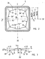
- FIGS. 1 and 2 represent a longitudinal and a cross section through the same Embodiment of a mold according to the invention.
- the mold has Chill tube 5, which has a mold cavity 10 with a casting cone 10 ', one Pouring opening 11 and an outlet opening 12 forms.
- FIGS. 1 and 2 concentrate the representations in FIGS. 1 and 2 - the present problem accordingly - on the mold tube 5, in particular the geometry of the pouring cone 10 '. Additional components, one in the foundry Make usable mold are omitted in Figures 1 and 2.
- the casting cone 10 ' is in a longitudinal section 15' of the mold cavity 10 between a cross-sectional area 24 in the vicinity of the inlet opening 11 and the Exit opening 12 formed.
- the pouring cone 10 'in FIGS. 1 and 2 is in the direction of the outlet opening 12 increasing narrowing of the mold cavity 10 is drawn in excessively large.
- 2 shows a plan view of a longitudinal section of the mold tube 5, which is delimited on one side by the cross-sectional area 24 and on the other hand by a cross-sectional area 25 between the cross-sectional area 24 and the outlet opening 12.
- FIG. 1 again illustrates 2 shows a longitudinal section along the line I - I in FIG. 2.
- the mold cavity 10 has four corner areas 13 in the form of fillets.
- the corner areas 13 are defined by intermediate areas 14 ', 14 ", 14' '', 14" "in the form of curved surfaces connected.
- Fig. 1 the course of the corner areas 13 is in each case indicated by a line 13, which is the cutting line of the mold cavity delimiting surface and the diagonal surfaces of the mold cavity 10 result.
- the sections are the circumferential line of the mold cavity 10, which each connect two corner regions 13 in the cross-sectional area 24, straight lines.
- the corresponding sections 26 ', 26 ", 26" “, 26” “of the The circumferential line 26 of the mold cavity 10 in the cross-sectional area 25 is in pieces arcuate lines. Two of the sections 26 ', 26 ", 26"', 26 “” butt each at one of the corner areas 13 at a right angle, determined as Intersection angle of the tangents of the respective sections on the relevant one Corner area 13, together.
- the inside width of the mold cavity increases 10 in the middle 32 in the direction of the outlet opening 12 linear with the distance Z from the one-sided end of the casting cone 10 '.
- In and / or at the corner areas 13 takes the inside width of the mold cavity 10 at the end on the pouring side 24 of the casting cone 10 'initially much stronger with the distance from end 24 of the pouring cone 10 ′ on the pouring side than in the middle 32 of the intermediate regions 14 ', 14 ", 14"', 14 "”.
- the relative change in the inside width of the mold cavity 10 is determined in and / or at one of the corner areas 13, as a function of the distance Z and reaches values of the same order of magnitude as the relative change the clear width, determined in the middle 32 of the intermediate areas 14 ', 14 ", 14 '' ', 14 "".
- the casting cone 10 ' can be characterized quantitatively by specifying the conicity K, which is defined in this context as the quotient of the magnitude of the gradient of the inside width of the mold cavity 10 and the inside width, in each case determined for a specific location in the corner areas 13 or the intermediate areas 14 ', 14 ", 14''', 14 '''' in units of% / m.
- the indices "M" or "E” refer to the center 32 or the corner regions 13, the sizes W M or W E according to FIG. 2 half the clear width of the mold cavity 10 in the center 32 of the intermediate regions 14 ' , 14 ", 14"'and 14 “” or in and / or at one of the corner regions 13 and Z 2 denotes the distance of the cross-sectional area 25 from the pour-side end 24 of the casting cone 10'.
- the other sections 26 ′′, 26 ′′ ′′ and 26 ′′ ′′ can be treated analogously.
- right angles 13 ′ are drawn, which each mark the angle that section 26 ′ has with one of the adjacent sections 26 ′′. or 26 "" in the corner areas 13, each defined by the tangents shown as dashed, horizontal or vertical lines.
- Arrows P W in FIG. 3 indicate turning points on the section 26 ′ of the circumferential line 26, which mark a reversal of the sign of the curvature along the circumferential line 26.
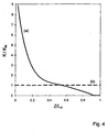
- FIGS. 4-6 Quantitative results of the simulations are shown in FIGS. 4-6 for a mold tube 5 optimized according to the above criteria.
- the two curves are standardized with respect to K M (Z).
- Z is specified in units of the length L K of the section 15 ', ie the longitudinal extent of the casting cone 10' in the casting direction. 4, the taper K M (Z) is constant.
- the taper K E (Z) at the pouring end 24 of the pouring cone 10 ' is approximately a factor 8 greater than K M (Z) and decreases at least in parts non-linearly and / or parabolically and / or linearly as the distance Z increases.
- the course of K M (Z) is compatible with K E (Z) ⁇ K M (Z) for Z> 0.6 L K.
- the simulation thus suggests that the taper K varies at least in the region of a partial length 15 of the casting cone 10 '(see FIG. 1) along a circumferential line of any cross-sectional area, for example the cross-sectional area 25, such that the taper K to the center of the intermediate regions 14 ', 14 ", 14"' and 14 "" decreases.
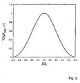
- this normalized form as shown in FIG.
- ⁇ Y max is in the range ⁇ Y max ⁇ 1 mm.
- FIGS. 4-6 can be modified to a certain extent without significantly influencing the properties of the mold according to the invention.
- the requirement suggested by FIG. 5 could be waived that the shape of the intermediate areas 14 ', 14 ", 14"' and 14 "” by a single, suitably standardized function of a variable and the specification of the conicity K E (Z) and K M (Z) is represented.
- waiving this requirement leads to tolerable changes that can be compensated for by a corresponding change in the courses of K E (Z) and K M (Z).
- the circumference of a cross-sectional area of the mold cavity 10 in the area of the casting cone 10 'between the corner areas 13 should be a smooth curve. Studies have shown that selective abrupt changes in the direction of the tangent when passing through a Point between the corner areas 13, the formation of columns between the Convey the cavity wall and the strand shell in the vicinity of this point and disrupt the growth of the strand shell locally, even if the direction the tangent abruptly changes by only 2 ° when passing through this point changes.
- the dashed line in FIG. 6 describes a section of a circumferential line of the mold cavity of a mold, the pouring cone of which follows the "natural shrinkage" of the strand shell.
- the intermediate regions are curved in an S-shape, with a circumferential line in a cross-sectional area of the mold cavity 10 in the region of the S-shaped sections of the intermediate regions 14 ', 14 "
- the position of the turning points and the width of the S-shaped curved sections of the intermediate areas 14 ', 14 ", 14"",14”" depends heavily on Distance Z 2 from the pour-side end 24 of the casting cone 10 ′, in particular for small Z 2 .
- the optimized mold represented by the parameters in FIGS. 4 and 5 or the solid line in FIG.
- the concept of natural shrinkage leads to shapes of the intermediate regions which are in one cross-sectional area of the mold cavity 10 at the corner regions 13 in one the region widening as the distance Z 2 widens significantly more and consequently also have a greater relative change in the taper K along the circumferential line of a cross-sectional area, based on the width of the S-shaped sections.
- a mold represented by the parameters in FIGS. 4 and 5 is therefore suitable for higher pull-out speeds.
- results discussed above are for straight and curved mold cavities applicable.
- the results mentioned are not only applicable to molds for Continuous casting of essentially square strands. they are transferable to molds for the casting of essentially polygonal ones Strands with at least three corner areas and three intermediate areas. at such molds, it is advantageous if two of those adjacent to one of the corner areas Intermediate areas form a corner angle that is independent of the distance from the pour end of the pouring cone.
- the shape of the Intermediate areas are those discussed in connection with FIGS. 4, 5 and 6 Statements applicable.
- the aforementioned embodiment of the mold according to the invention relates on a pouring cone, the circumferential lines between the corner areas are formed from straight lines at the pouring end of the casting cone 10 ' and that with increasing distance from the pouring end 24 of the pouring cone 10 'have an increasingly convex curvature.
- the perimeter lines of the mold cavity at the outlet opening 12 between the corner areas 13 straight and concave at the pouring end 24 of the casting cone are.
Abstract
Description
Die Erfindung bezieht sich auf eine Kokille zum Stranggiessen von im wesentlichen
polygonalen Strängen, gemäss dem Oberbegriff des Anspruchs 1.The invention relates essentially to a mold for continuous casting
polygonal strands, according to the preamble of
Beim Stranggiessen, insbesondere beim Stranggiessen von Stahl, wird kontinuierlich eine Metallschmelze durch eine Eingiessöffnung in einen Formhohlraum einer Kokille gegossen, durch Abkühlen der Schmelze an den Wänden des Formhohlraums eine Strangschale kontinuierlich wachsender Dicke gebildet und aus einer Austrittsöffnung des Formhohlraums kontinuierlich ein Strang gezogen, der in der Regel einen noch flüssigen Kem aufweist und bis zur vollständigen Durcherstarrung einer Nachkühlung unterzogen werden muss. Von besonderer Bedeutung für die Qualität der hergestellten Stränge und für die Produktivität der Stranggiessanlage ist die Formgebung der Formhohlraumwände. Die Wechselwirkung der sich bildenden Strangschale mit den Formhohlraumwänden bestimmt einerseits den Wärmeübergang zwischen Strangschale und den Formhohlraumwänden und folglich auch das Wachstum der Strangschale. Die Wechselwirkung der Strangschale mit den Formhohlraumwänden hat auch Einfluss auf die Grösse der Reibungskräfte, die beim Ausziehen eines Stranges aus dem Formhohlraum überwunden werden müssen und wegen der limitierten mechanischen Stabilität der Strangschale, abhängig von der chemischen Zusammensetzung der Schmelze, einen bestimmten kritischen Wert nicht überschreiten dürfen, wenn unerwünschte, die Produktivität der Stranggiessanlage herabsetzende Strangabrisse oder Strangdurchbrüche vermieden werden sollen.Continuous casting, especially continuous casting of steel, is continuous a molten metal through a pouring opening into a mold cavity poured into a mold by cooling the melt on the walls of the Mold cavity formed a strand shell and continuously increasing thickness continuously pulled a strand from an outlet opening of the mold cavity, which usually has a still liquid core and is complete Solidification must be subjected to post-cooling. Of special Significance for the quality of the strands produced and for productivity The continuous caster is the shape of the mold cavity walls. The Interaction of the strand shell that forms with the mold cavity walls determines the heat transfer between the strand shell and the mold cavity walls and consequently the growth of the strand shell. The interaction the strand shell with the mold cavity walls also has an influence to the magnitude of the frictional forces that arise when pulling a strand from the Mold cavity must be overcome and because of the limited mechanical Stability of the strand shell, depending on the chemical composition the melt, do not exceed a certain critical value may, if undesirable, reduce the productivity of the continuous caster Strand breaks or strand breaks should be avoided.
Um beim Stranggiessen eine möglichst hohe Giessgeschwindigkeit zu erreichen und gleichzeitig Strangabrisse bzw. Strangdurchbrüche zu vermeiden, sollten die Formhohlraumwände so geformt sein, dass ein möglichst gleichmässiges Strangschalenwachstum realisiert wird. Verschiedene konstruktive Massnahmen sind bekannt, um das Strangschalenwachstum zu optimieren. Um die Bildung von Spalten zwischen den Formhohlraumwänden und der Strangschale aufgrund der in Richtung auf die Austrittsöffnung zunehmende thermische Kontraktion zu vermeiden, wird der Formhohlraum in Form eines Giesskonus gestaltet, der der thermischen Kontraktion des Stranges Rechnung tragen soll.To achieve the highest possible casting speed during continuous casting and at the same time to avoid strand breaks or strand breaks, the Mold cavity walls should be shaped so that they are as uniform as possible Strand shell growth is realized. Various constructive measures are known to optimize strand shell growth. To education due to gaps between the mold cavity walls and the strand shell the increasing thermal contraction in the direction of the outlet opening avoid, the mold cavity is designed in the form of a casting cone that the thermal contraction of the strand should take into account.
Die optimale Formung des Giesskonus ist ein generelles Problem, wegen der Vielzahl der Parameter, die auf das Strangschalenwachstum bekanntermassen einen Einfluss haben. Beispielsweise spielen die chemische Zusammensetzung der Metallschmelze, die Form und die Grösse des Querschnitts des Formhohlraums und die Giessgeschwindigkeit eine Rolle.The optimal shaping of the pouring cone is a general problem because of the Variety of parameters known to increase strand shell growth have an influence. For example, the chemical composition play of the molten metal, the shape and size of the cross section of the mold cavity and the casting speed matter.
Bei eckigen Formhohlräumen verdienen die Mechanismen, die das Strangschalenwachstum in den Eckbereichen des Stranges bestimmen, eine besondere Beachtung. Je nach Ausgestaltung des Giesskonus besteht die Gefahr, dass die Strangschale in den Ecken des Formhohlraums mit einer übermässig grossen Anpresskraft an die Formhohlraumwände gepresst und so ein Verklemmen des Stranges im Formhohlraum verursacht wird oder, in einem anderen Extremfall, aufgrund der thermischen.Kontraktion der Strangschale in wenigstens einer der Ecken des Formhohlraums der Bildung eines Spaltes zwischen der Strangschale und den Formhohlraumwänden Vorschub geleistet und wegen der Spaltbildung die Wärmeabfuhr lokal vermindert wird. Die Reduktion der Wärmeabfuhr in einer Ecke wiederum kann zur Folge haben, dass die Strangschale in der Ecke deutlich langsamer wächst als an den Seitenflächen des Formhohlraums oder - im Extremfall - sogar wieder aufschmilzt und einen Durchbruch erleidet. Die Bildung von Spalten zwischen der Strangschale und den Formhohlraumwänden erschwert weiterhin die Herstellung von Strängen mit einer genau kontrollierten Geometrie und führt zu unerwünschten, unkontrollierbaren Strangverzügen und zu Strängen mit Oberflächenfehlern.In the case of angular mold cavities, the mechanisms that promote strand shell growth determine a special one in the corner areas of the strand Attention. Depending on the design of the pouring cone, there is a risk that the Strand shell in the corners of the mold cavity with an excessively large one Pressing force is pressed against the mold cavity walls and thus a jamming of the Strand is caused in the mold cavity or, in another extreme case, due to the thermal contraction of the strand shell in at least one of the Corners of the mold cavity forming a gap between the strand shell and the mold cavity walls and because of the gap formation the heat dissipation is locally reduced. The reduction of heat dissipation in one Corner in turn can result in the strand shell being clearly in the corner grows more slowly than on the side surfaces of the mold cavity or - in Extreme case - even melts again and suffers a breakthrough. The education difficult by gaps between the strand shell and the mold cavity walls continue to manufacture strands with a precisely controlled Geometry and leads to undesirable, uncontrollable strand distortion and to strands with surface defects.
Zusätzlich können Temperaturgradienten, in Verbindung mit der thermischen Kontraktion der Strangschale, eine Veränderung der Form einer Querschnittsfläche eines Strangabschnitts im Formhohlraum auf dem Wege des Strangabschnitts zur Austrittsöffnung fördern. Zur Optimierung eines Giesskonus ist es deshalb sinnvoll, zwei Freiheitsgrade, quantitativ beschrieben durch die räumliche Abhängigkeit der Konizität K, zu nutzen, die die Veränderung der Grösse und der Form einer Querschnittsfläche des Formhohlraums in Stranglaufrichtung in Abhängigkeit von der Position der Querschnittsfläche beschreiben.In addition, temperature gradients, in conjunction with the thermal Contraction of the strand shell, a change in the shape of a cross-sectional area a strand section in the mold cavity on the way of the strand section convey to the outlet opening. It is to optimize a pouring cone therefore meaningful, two degrees of freedom, quantitatively described by the spatial Dependency of the taper K, to use the change in size and the shape of a cross-sectional area of the mold cavity in the strand running direction describe depending on the position of the cross-sectional area.
Die Patentschrift US 4 207 941 beschreibt eine Kokille, die für das Stranggiessen von im wesentlichen quadratischen Strängen vorgesehen ist. Der Formhohlraum dieser Kokille wird durch ein über seine gesamte Längserstreckung konisches Rohr gebildet, das drei aneinandergrenzende, hinsichtlich der Grösse und der Ortsabhängigkeit der Konizität unterscheidbare Längsabschnitte umfasst: Einen Eingangsabschnitt, der sich im Giessbetrieb oberhalb des Giesspiegels befindet; einen Mittelabschnitt, an dessen oberen Ende im Giessbetrieb der Giessspiegel positioniert wird und in dem die Anfangserstarrung des Stranges stattfindet; und einen Endabschnitt, der die Strangschale an der Austrittsöffnung stützt.US Pat. No. 4,207,941 describes a mold used for continuous casting of essentially square strands is provided. The mold cavity of this mold is formed by a tube that is conical over its entire length, the three adjacent, in terms of size and location longitudinal sections which can be distinguished by the conicity include: an entrance section, located in the foundry above the pouring level; a middle section, at the upper end of which in the casting operation the pouring mirror is positioned and in which the initial solidification of the strand takes place; and an end section that supports the strand shell at the outlet opening.
Der Eingangsabschnitt weist vier gekrümmte Eckbereiche auf, die jeweils durch ebene Zwischenbereiche verbunden sind, wobei jeweils zwei der Zwischenbereiche an einem der Eckbereiche in einem rechten Winkel aneinanderstossen. Die Konizität ist im Bereich des Eingangsabschnitts konstant, d.h. die lichte Weite des Formhohlraums nimmt linear mit dem Abstand von der Eingiessöffnung ab. Im Mittelabschnitt hängt die Konizität des Formhohlraumes sowohl vom Abstand von der Eingiessöffnung als auch von der Position in einer Ebene quer zur Stranglaufrichtung ab. Der Mittelabschnitt setzt sich zusammen aus gekrümmten Eckbereichen, die jeweils durch einen aus drei ebenen, in einem stumpfen Winkel aneinanderstossenden Facetten gebildeten Zwischenbereich verbunden sind. Die Konizität ist am grössten in den Eckbereichen des Mittelabschnitts und hier unabhängig von der Position in Stranglaufrichtung. Zwei der drei jeweils einen der Zwischenbereiche bildenden Facetten grenzen jeweils an einen der Eckbereiche an und haben die Form von Dreiecken, die sich in Stranglaufrichtung linear als Funktion des Abstandes von der Eingiessöffnung verbreitern. An jedem der Eckbereiche stossen jeweils zwei der dreieckigen Facetten benachbarter Zwischenbereiche in einem Winkel von ca. 92° aneinander. Bei dieser Konstruktion der Zwischenbereiche des Mittelabschnitts ist die Konizität auf jeder der Facetten konstant, wobei die Konizität auf den dreieckigen, an einen der annähernd rechtwinkligen Eckbereiche angrenzenden Facetten am grössten ist. An den Grenzen zwischen den Facetten treten Sprünge der Konizität auf.The entrance section has four curved corner areas, each through planar intermediate areas are connected, two of each of the intermediate areas abut one another at a right angle at one of the corner areas. The taper is constant in the area of the entrance section, i.e. the light The width of the mold cavity increases linearly with the distance from the pouring opening from. In the middle section, the taper of the mold cavity depends both on Distance from the pouring opening as well as from the position in one plane across to the direction of the strand. The middle section is composed of curved Corner areas, each by one of three levels, in one obtuse angles between facets forming an intermediate area are connected. The taper is greatest in the corner areas of the central section and here regardless of the position in the strand running direction. Two of the three facets each forming one of the intermediate areas are adjacent one of the corner areas and have the shape of triangles, which are in Line direction linear as a function of the distance from the pouring opening broaden. Two of the triangular areas meet at each of the corner areas Facets of neighboring intermediate areas at an angle of approx. 92 ° to each other. In this construction, the intermediate areas of the middle section is the Taper constant on each of the facets, with taper on the triangular, to one of the facets bordering approximately rectangular corners is greatest. At the boundaries between the facets there are cracks Conicity.
Im Bereich des Endabschnitts hat der Formhohlraum die gleiche zwölfeckige Form wie an der Grenze zwischen dem Endabschnitt und dem Mittelabschnitt. Dabei ist die Konizität im gesamten Endabschnitt konstant und kleiner als die Konizität im Bereich der verschiedenen Facetten, die den Mittelabschnitt des Kokillenrohrs bilden. Somit ist bei der in US 4 207 941 beschriebenen Kokille der grösste Teil der Formhohlraumverengung auf den Mittelabschnitt und im Bereich des Mittelabschnitts auf eckennahe, sich in Stranglaufrichtung verbreiternde ebene Bereiche konzentriert. Ein Nachteil dieser Kokille ist darin zu sehen, dass in den zwölfeckigen Bereichen des Formhohlraums nicht verhindert werden kann, dass sich die Strangschale lokal von den Formhohlraumwänden ablöst und eine Form annimmt, die während des Strangauszugs der Form der Formhohlraumwände nicht perfekt folgt und deren Geometrie nur ungenau kontrollierbar ist. Die Folge sind einerseits eine Bildung von Spalten zwischen der Strangschale und den Formhohlraumwänden, verbunden mit einer lokalen Reduktion der Wärmeabfuhr. Andererseits können lokale Erhöhungen der Anpresskräfte zwischen der Strangschale und den Formhohlraumwänden auftreten, so dass die Reibungskräfte nicht auf ein Minimum reduziert sind. Diese Effekte limitieren die maximale Giessgeschwindigkeit, die im Giessbetrieb routinemässig erzielbar ist.In the area of the end section, the mold cavity has the same twelve-sided shape Shape like at the border between the end section and the middle section. The taper in the entire end section is constant and smaller than that Taper in the area of the various facets that cover the central section of the Form the mold tube. Thus, in the mold described in US 4,207,941 Most of the mold cavity narrowing to the middle section and in the area of the central section on the corner, widening in the direction of the strand level areas concentrated. One disadvantage of this mold is that cannot be prevented in the twelve-sided areas of the mold cavity may cause the strand shell to detach itself locally from the mold cavity walls and assumes a shape which, during the extrusion of the shape of the Mold cavity walls do not follow perfectly and their geometry can only be controlled with imprecision is. The result is, on the one hand, the formation of gaps between the Strand shell and the mold cavity walls, combined with a local reduction the heat dissipation. On the other hand, local increases in the contact pressure occur between the strand shell and the mold cavity walls, so that the frictional forces are not reduced to a minimum. These effects limit the maximum casting speed, which is routine in casting operation is achievable.
Aus EP-B-0 498 296, die den Oberbegriff von Anspruch 1 bildet, ist eine Kokille zum Stranggiessen
von im wesentlichen polygonalen Strängen bekannt. Die Kokille weist einen Formhohlraum
mit einer Eingiessöffnung und einer Strangäustrittsöffnung auf. Der Formhohlraum ist
mindestens im Bereich einer Teillänge der Kokille mit Giesskonizitäten versehen, die entlang
des Formhohlraumumfanges in den Eckbereichen und in den Zwischenbereichen zwischen den
Eckbereichen unterschiedlich sind. In den Eckbereichen wird vorgeschlagen, die Konizität gering,
null oder sogar negativ auszuführen. Zur Mitte des Zwischenbereiches hin soll entlang einer
gebogenen Kurve die Konizität zunehmen, um in den Zwischenbereichen Schwindungsspalte
zwischen der Strangoberfläche und der Kokillenwand zu vermeiden.From EP-B-0 498 296, which forms the preamble of
Ausgehend von den genannten Nachteilen des Standes der Technik, stellt sich der Erfindung die Aufgabe, zum Stranggiessen von im wesentlichen polygonalen Strängen eine Kokille mit einem Formhohlraum zu schaffen, der eine erhöhte Giessgeschwindigkeit ermöglicht.Based on the disadvantages of the prior art mentioned, it turns out the object of the invention for the continuous casting of essentially polygonal Strands create a mold with a mold cavity that increases Casting speed enabled.
Diese Aufgabe wird gelöst durch eine Kokille mit der Gesamtheit der Merkmale
des Anspruchs 1.This problem is solved by a mold with all the features
of
Die erfindungsgemässe Kokille weist einen Formhohlraum auf mit mindestens drei Eckbereichen und drei Zwischenbereichen zwischen den Eckbereichen und mit einem Giesskonus. Die Konizität variiert wenigstens im Bereich einer Teillänge des Giesskonus entlang einer Umfangslinie in einer Querschnittfläche in einem oder mehreren der Zwischenbereiche derart, dass die Konizität zur Mitte des jeweiligen Zwischenbereichs hin abnimmt. Diese Gestaltung des Giesskonus berücksichtigt die Tendenz einer sich im Formhohlraum bildenden Strangschale, aufgrund ihrer mechanischen Stabilität unter dem Einfluss des in die Strangschale eingeprägten Temperaturprofils und des ferrostatischen Drucks während des Abkühlens beim Strangauszug in den Eckbereichen stärker zu schrumpfen als in der Mitte der Zwischenbereiche. Weiterhin ist bei der erfindungsgemässen Kokille vorgesehen, dass im Bereich der genannten Teillänge die Umfangslinie zwischen den Eckbereichen eine glatte Kurve, d.h. eine Kurve, deren Tangente längs des Kurvenverlaufs nicht unstetig ihre Richtung ändert, bildet. Auf diese Weise wird vermieden, dass sich an der Oberfläche der Strangschale zwischen den Eckbereichen des Formhohlraums Kanten ausbilden, dieabhängig von der Form des Giesskonus - Anlass geben können für unerwünschte Spaltbildungen oder für lokal erhöhte Anpresskräfte zwischen der Strangschale und den Formhohlraumwänden. Durch diese Massnahmen wird die Spaltbildung auf dem gesamten Umfang des Formhohlraums vermieden, ein auf dem gesamten Umfang des Formhohlraums gleichmässiges Strangschalenwachstum erzielt und die Reibungskräfte zwischen der Strangschale und den Formhohlraumwänden reduziert. Dadurch wird das Giessen mit einer erhöhten Giessgeschwindigkeit möglich. Zusätzlich kann wegen der reduzierten Reibung der Abstand des Giessspiegels von der Austrittsöffnung des Formhohlraums vergrössert werden, mit der Folge, dass die Strangschale an der Austrittsöffnung dicker ist und eine verbesserte mechanische Stabilität aufweist.The mold according to the invention has a mold cavity with at least three corner areas and three intermediate areas between the corner areas and with a pouring cone. The taper varies at least in the partial length range of the casting cone along a circumferential line in a cross-sectional area in one or more of the intermediate areas such that the taper to the center of the respective intermediate area decreases. This design of the pouring cone takes into account the tendency of a strand shell forming in the mold cavity, due to their mechanical stability under the influence of the Strand shell of the impressed temperature profile and the ferrostatic pressure during cooling when pulling out the strand in the corner areas shrink than in the middle of the intermediate areas. Furthermore, according to the invention Mold provided that in the area of the partial length mentioned the circumferential line between the corner areas is a smooth curve, i.e. a curve, whose tangent does not change its direction discontinuously along the curve, forms. In this way it is avoided that on the surface of the strand shell Form edges between the corner areas of the mold cavity, depending on the from the shape of the pouring cone - can give rise to undesirable Gaps or for locally increased contact forces between the Strand shell and the mold cavity walls. Through these measures the Avoid formation of gaps on the entire circumference of the mold cavity, one on uniform shell shell growth over the entire circumference of the mold cavity achieved and the frictional forces between the strand shell and the Mold cavity walls reduced. This will increase the casting Casting speed possible. In addition, due to the reduced friction the distance of the pouring mirror from the outlet opening of the mold cavity be enlarged, with the result that the strand shell at the outlet opening is thicker and has improved mechanical stability.
Bei einer Ausführungsform der erfindungsgemässen Kokille ist der Giesskonus in einem Teilabschnitt des Formhohlraums ausgebildet.In one embodiment of the mold according to the invention is the casting cone formed in a portion of the mold cavity.
Um die Voraussetzung für ein gleichmässiges Strangschalenwachstum zu schaffen, ist vorgesehen, dass die Konizität mit dem Abstand vom eingiessseitigen Ende des Giesskonus variiert. Bei einer bevorzugten Ausführungsform der erfindungsgemässen Kokille ist die Konizität in der Mitte der Zwischenbereiche im Bereich der Teillänge unabhängig vom Abstand vom eingiessseitigen Ende des Giesskonus, d.h. die lichte Weite des Formhohlraums ändert sich bezogen auf die Mitte der Zwischenbereiche, linear mit dem Abstand vom eingiessseitigen Ende des Giesskonus. Am eingiessseitigen Ende des Giesskonus ist die Konizität in und/oder an den Eckbereichen zunächst grundsätzlich grösser als in der Mitte der Zwischenbereiche, nimmt aber mindestens stückweise nichtlinear und/oder linear und/oder parabolisch mit dem Abstand vom eingiessseitigen Ende des Giesskonus ab. Am austrittsseitigen Ende des Giesskonus kann die Konizität in und/oder an den Eckbereichen gleich oder sogar kleiner sein als die Konizität in der Mitte der Zwischenbereiche.To meet the prerequisite for even strand shell growth create, it is provided that the taper with the distance from the pouring side The end of the pouring cone varies. In a preferred embodiment of the The mold according to the invention is the taper in the middle of the intermediate areas in the area of the partial length regardless of the distance from the end on the pouring side the pouring cone, i.e. the clear width of the mold cavity changes in relation to the middle of the intermediate areas, linear with the distance from the pouring side End of the pouring cone. At the pouring end of the pouring cone is the Taper in and / or at the corner areas is generally larger than in the middle of the intermediate areas, but takes at least piecewise non-linear and / or linear and / or parabolic with the distance from the pour end of the pouring cone. At the exit end of the pouring cone, the taper can be in and / or at the corner areas may be the same or even smaller than that Taper in the middle of the intermediate areas.
Ein gleichmässiges Strangschalenwachstum ist mit der erfindungsgemässen Kokille beispielsweise bei einer Konizität erzielbar, die in der Mitte der Zwischenbereiche, gemittelt über die gesamte Länge des Giesskonus, 0 - 0.7 %/m, vorzugsweise 0.2 - 0.6 %/m, beträgt und in und/oder an den Eckbereichen, gemittelt über die gesamte Länge des Giesskonus, einen Wert im Bereich 0.7 - 1.5 %/m, vorzugsweise 0.8 - 1.3 %/m, annimmt.Uniform strand shell growth is possible with that of the invention For example, mold can be achieved with a taper that is in the middle of the intermediate areas, averaged over the entire length of the casting cone, 0 - 0.7% / m, is preferably 0.2-0.6% / m, and averaged in and / or at the corner areas over the entire length of the casting cone, a value in the range 0.7 - 1.5 % / m, preferably 0.8 - 1.3% / m.
Zur Minimierung der zwischen der Strangschale und den Formhohlraumwänden wirkenden Anpresskräfte, die in der Regel an den Eckbereichen am grössten sind, können mehrere Massnahmen - allein oder in Kombination miteinanderangewendet werden. Bei einer Ausführungsform der erfindungsgemässen Kokille ist die Umfangslinie in einer Querschnittsebene des Formhohlraums im Bereich der Teillänge mindestens stückweise bogenförmig und/oder geradlinig. In jedem der Zwischenbereiche findet zwischen einem der angrenzenden Eckbereiche und der Mitte des Zwischenbereichs eine Umkehr der Krümmung statt. Eine Umfangslinie mit einem kontinuierlichen Verlauf der Krümmung weist deshalb zwischen der Mitte des Zwischenbereiches und den angrenzenden Eckbereichen einen Wendepunkt auf.To minimize the space between the strand shell and the mold cavity walls effective contact forces, which are usually greatest at the corner areas several measures can be used - alone or in combination become. In one embodiment of the mold according to the invention is the circumferential line in a cross-sectional plane of the mold cavity in the area the partial length is at least piece-like arched and / or rectilinear. In each the intermediate area takes place between one of the adjacent corner areas and the center of the intermediate area is reversed in curvature. A Circumference with a continuous course of curvature therefore points between the middle of the intermediate area and the adjacent corner areas a turning point.
Eine weitere Ausführungsform der erfindungsgemässen Kokille zeichnet sich dadurch aus, dass im Bereich der Teillänge jeder Abschnitt der Umfangslinie in einer Querschnittsfläche des Formhohlraums zwischen den Eckbereichen durch eine universelle Kurve repräsentierbar ist, die - normiert bezüglich ihrer Extremwerte - unabhängig ist vom Abstand vom eingiessseitigen Ende des Giesskonus. Diese Vorgabe einer universellen Kurve hat verschiedene Vorteile. Fertigungstechnisch ergibt sich der Vorteil, dass so der Giesskonus durch nur wenige Parameter charakterisierbar ist. Es genügt beispielsweise die Angabe der universellen Funktion, die eine Ortskoordinate als Variable aufweist, und des Verlaufs der Konizität an den Eckbereichen und in der Mitte des Zwischenbereichs als Funktion des Abstands vom eingiessseitigen Ende des Giesskonus. Eine besonders einfache Parametrisierung der Umfangslinie ergibt sich bei einer Darstellung als Parabel vierter Ordnung. Weiterhin zeigt eine Analyse der Anpresskräfte zwischen der Strangschale und den Formhohlraumwänden, dass bei dieser Form der Umfangslinie besonders geringe Anpresskräfte resultieren. Eine Voraussetzung für möglichst geringe Anpresskräfte ist eine geringe Krümmung der Umfangslinie. Diese Voraussetzung wird beispielsweise realisiert durch eine Umfangslinie mit einem Wendepunkt zwischen der Mitte eines der Zwischenbereiche und einem der angrenzenden Eckbereiche.Another embodiment of the mold according to the invention is distinguished characterized in that each section of the circumferential line in a cross-sectional area of the mold cavity between the corner regions a universal curve can be represented that - normalizes with regard to its extreme values - is independent of the distance from the pour-side end of the pouring cone. This specification of a universal curve has several advantages. manufacturing technology there is the advantage that the pouring cone has only a few Parameter can be characterized. For example, it is sufficient to specify the universal function, which has a location coordinate as a variable, and the Course of the taper at the corner areas and in the middle of the intermediate area as a function of the distance from the pour-side end of the pouring cone. A particularly simple parameterization of the circumferential line results in a Representation as a fourth-order parabola. Furthermore, an analysis of the Contact forces between the strand shell and the mold cavity walls that this form of the circumferential line results in particularly low contact forces. A prerequisite for the lowest possible contact pressure is a slight curvature the circumference. This requirement is met, for example by a circumference with an inflection point between the center of one of the Intermediate areas and one of the adjacent corner areas.
Ein besonders gleichmässiges Strangschalenwachstum ist erzielbar, wenn zwei der an einem der Eckbereiche anstossende Abschnitte der Umfangslinie einen Winkel bilden, der im Bereich der Teillänge unabhängig vom Abstand vom eingiessseitigen Ende des Giesskonus ist. Eine Ausführungsform der erfindungsgemässen Kokille weist einen Formhohlraum auf, dessen Querschnittsfläche am eingiessseitigen Ende des Giesskonus Eckbereiche mit einem Eckwinkel von jeweils 90° umfasst und dessen Zwischenbereiche auf der gesamten Länge des Giesskonus in einem rechten Winkel aufeinandertreffen. Dieses Designkonzept ist darin begründet, dass ein Strang, der im Bereich der Anfangserstarrung eine rechteckige Querschnittsfläche aufweist, beim Abkühlen in der Kokille während des Strangauszugs dazu neigt, derart zu schrumpfen, dass in unmittelbarer Umgebung der Ecken die Seitenflächen des Stranges in einem rechten Winkel aufeinandertreffen. Diese Winkelerhaltung im Verlauf des Schrumpfprozesses ist ein Resultat des Zusammenwirkens der mechanischen Eigenschaften der Strangschale mit dem in der Strangschale ausgebildeten Temperaturprofil und dem auf die Strangschale wirkenden ferrostatischen Druck. A particularly even strand shell growth can be achieved if two the portions of the circumferential line that abut one of the corner regions Form an angle in the area of the partial length regardless of the distance from the pouring side Is the end of the pouring cone. An embodiment of the invention Chill mold has a mold cavity whose cross-sectional area on pouring end of the pouring cone corner areas with a corner angle of each 90 ° and its intermediate areas along the entire length of the The pouring cone meet at a right angle. This design concept is based on the fact that a strand which is a has rectangular cross-sectional area during cooling in the mold while the strand pull-out tends to shrink in such a way that in the immediate vicinity the corners of the sides of the strand meet at a right angle. This conservation of angles during the course of the shrinking process is a result of the interaction of the mechanical properties of the Strand shell with the temperature profile and formed in the strand shell the ferrostatic pressure acting on the strand shell.
Der Formhohlraum der erfindungsgemässen Kokille kann in den Eckbereichen Hohlkehlen mit einem Radius von 2 - 8 % der lichten Weite der Austrittsöffnung aufweisen.The mold cavity of the mold according to the invention can be in the corner areas Fillets with a radius of 2 - 8% of the clear width of the outlet opening exhibit.
Anhand der folgenden Figuren wird ein bevorzugtes Ausführungsbeispiel der Erfindung erläutert.The following figures illustrate a preferred embodiment of the invention explained.
Es zeigen:
- Fig. 1
- einen Längsschnitt durch eine erfindungsgemässe Kokille mit einem einen Formhohlraum bildenden Kokillenrohr,
- Fig. 2
- einen Querschnitt durch einen Längsabschnitt der erfindungsgemässen Kokille längs der Ebene II - II in Fig. 1,
- Fig. 3
- eine schematische funktionelle Darstellung eines Abschnitts einer
Umfangslinie eines Querschnitts durch den Formhohlraum der Kokille
in Fig. 1 längs der
Ebene 25, - Fig. 4
- die Ortsabhängigkeit der Konizität der Kokille gemäss Fig. 1 in Längsrichtung der Kokille längs verschiedener Wege,
- Fig. 5
- eine normierte Darstellung eines Abschnitts der Umfangslinien verschiedener Querschnitte durch den Formhohlraum der Kokille in Fig. 1 und
- Fig. 6
- einen Vergleich einer Umfangslinie gemäss Fig. 5 mit einer entsprechenden Umfangslinie eines quadratischen Stranges nach einer vorgegebenen thermischen Kontraktion.
- Fig. 1
- 2 shows a longitudinal section through a mold according to the invention with a mold tube forming a mold cavity,
- Fig. 2
- 2 shows a cross section through a longitudinal section of the mold according to the invention along the plane II-II in FIG. 1,
- Fig. 3
- 2 shows a schematic functional illustration of a section of a circumferential line of a cross section through the mold cavity of the mold in FIG. 1 along the
plane 25, - Fig. 4
- 1 the position dependence of the conicity of the mold according to FIG. 1 in the longitudinal direction of the mold along different paths,
- Fig. 5
- a standardized representation of a portion of the circumferential lines of different cross sections through the mold cavity of the mold in Fig. 1 and
- Fig. 6
- a comparison of a circumferential line according to FIG. 5 with a corresponding circumferential line of a square strand after a predetermined thermal contraction.
Die Fig. 1 und 2 stellen einen Längs- und einen Querschnitt durch dasselbe
Ausführungsbeispiel einer erfindungsgemässen Kokille dar. Die Kokille weist ein
Kokillenrohr 5 auf, das einen Formhohlraum 10 mit einem Giesskonus 10', einer
Eingiessöffnung 11 und einer Austrittsöffnung 12 bildet. Der Einfachheit halber
konzentrieren sich die Darstellungen in den Fig. 1 und 2 - der vorliegenden Problemstellung
entsprechend - auf das Kokillenrohr 5, insbesondere die Geometrie
des Giesskonus 10'. Zusätzliche Komponenten, die eine im Giessbetrieb
verwendbare Kokille ausmachen, sind in den Figuren 1 und 2 weggelassen.1 and 2 represent a longitudinal and a cross section through the same
Embodiment of a mold according to the invention. The mold has
Der Giesskonus 10' ist in einem Längsabschnitt 15' des Formhohlraumes 10
zwischen einer Querschnittsfläche 24 in der Nähe der Eintrittsöffnung 11 und der
Austrittsöffnung 12 ausgebildet. Zur Veranschaulichung der Geometrie des
Giesskonus 10' ist in den Fig. 1 und 2 die in Richtung auf die Austrittsöffnung 12
zunehmende Verengung des Formhohlraums 10 übertrieben gross eingezeichnet.
Dabei zeigt Fig. 2 eine Draufsicht auf einen Längsabschnitt des Kokillenrohrs
5, der begrenzt ist auf der einen Seite durch die Querschnittsfläche 24 und
auf der anderen Seite durch eine Querschnittsfläche 25 zwischen der Querschnittsfläche
24 und der Austrittsöffnung 12. Fig. 1 wiederum veranschaulicht
einen Längsschnitt längs der Linie I - I in Fig. 2.The casting cone 10 'is in a longitudinal section 15' of the
Der Formhohlraum 10 weist vier Eckbereiche 13 in Form von Hohlkehlen auf.
Die Eckbereiche 13 sind durch Zwischenbereiche 14', 14", 14''', 14"" in Form von
gekrümmten Flächen verbunden. In Fig. 1 ist der Verlauf der Eckbereiche 13 jeweils
durch eine Linie 13 angedeutet, die sich als Schnittlinie der den Formhohlraum
begrenzenden Fläche und der Diagonalflächen des Formhohlraums 10
ergeben.The
Wie Fig. 2 zu entnehmen ist, sind die Abschnitte der Umfangslinie des Formhohlraums
10, die in der Querschnittsfläche 24 jeweils zwei Eckbereiche 13 verbinden,
gerade Linien. Die entsprechenden Abschnitte 26', 26", 26''', 26"" der
Umfangslinie 26 des Formhohlraums 10 in der Querschnittsfläche 25 sind stückweise
bogenförmige Linien. Jeweils zwei der Abschnitte 26', 26", 26"', 26"" stossen
an einem der Eckbereiche 13 in einem rechten Winkel, bestimmt als
Schnittwinkel der Tangenten der jeweiligen Abschnitte an dem betreffenden
Eckbereich 13, zusammen.As can be seen in FIG. 2, the sections are the circumferential line of the
Wie in Fig. 1 und 2 angedeutet ist, nimmt die lichte Weite des Formhohlraums
10 in der Mitte 32 in Richtung auf die Austrittsöffnung 12 linear mit dem Abstand
Z vom einseitigen Ende des Giesskonus 10' ab. In und/oder an den Eckbereichen
13 nimmt die lichte Weite des Formhohlraums 10 am eingiessseitigen Ende
24 des Giesskonus 10' zunächst wesentlich stärker mit dem Abstand vom
eingiessseitigen Ende 24 des Giesskonus 10' ab als in der Mitte 32 der Zwischenbereiche
14', 14", 14"', 14"". Bei Annäherung an die Austrittsöffnung nimmt
jedoch die relative Aenderung der lichten Weite des Formhohlraums 10, bestimmt
in und/oder an einem der Eckbereiche 13, als Funktion des Abstandes Z
ab und erreicht Werte von der gleichen Grössenordnung wie die relative Aenderung
der lichten Weite, bestimmt in der Mitte 32 der Zwischenbereiche 14', 14",
14''', 14"".As indicated in FIGS. 1 and 2, the inside width of the mold cavity increases
10 in the middle 32 in the direction of the outlet opening 12 linear with the distance
Z from the one-sided end of the casting cone 10 '. In and / or at the
Der Giesskonus 10' kann quantitativ charakterisiert werden durch Angabe der
Konizität K, welche in diesem Zusammenhang definiert ist als Quotient aus dem
Betrag des Gradienten der lichten Weite des Formhohlraums 10 und der lichten
Weite, jeweils ermittelt für einen bestimmten Ort in den Eckbereichen 13 bzw.
den Zwischenbereichen 14', 14", 14''', 14'''' in Einheiten von %/m. Gemäss dieser
Definition ist die Konizität K auf einem der Abschnitte 26', 26", 26''' und 26"" für
die Mitte 32 der Zwischenbereiche 14', 14", 14''', 14"" bzw. die Eckbereiche 13
charakterisierbar durch
Fig. 3 dient der Einführung von Koordinaten X und Y zur Darstellung eines Abschnittes
26' der Umfangslinie 26 in der Ebene 25 in Form einer Funktion
Y = Y (X, Z = Z2) mit dem Abstand Z2 der Querschnittsfläche 25 vom eingiessseitigen
Ende 24 des Giesskonus 10' als Parameter. Die anderen Abschnitte
26", 26''' und 26'''' können analog behandelt werden. In Fig. 3 sind rechte Winkel
13' eingezeichnet, die jeweils den Winkel markieren, den der Abschnitt 26' mit
einem der benachbarten Abschnitten 26" bzw. 26"" in den Eckbereichen 13,
jeweils definiert durch die als gestrichelte, horizontale bzw. vertikale Linien dargestellten
Tangenten, bilden. Der Ursprung des Koordinatensystems ist so gelegt,
dass der Abschnitt 26' beschränkt ist auf das Intervall [ - ΔYmax, 0 ] in Y-Richtung
und das Intervall [ - L/2, L/2 ] in X-Richtung, wobei L = 2 WE (Z2). Durch
Pfeile PW sind in Fig. 3 Wendepunkte auf dem Abschnitt 26' der Umfangslinie 26
angedeutet, die eine Umkehr des Vorzeichens der Krümmung längs der Umfangslinie
26 markieren.3 serves to introduce coordinates X and Y to represent a
Mittels Computersimulationen wurde die Geometrie der erfindungsgemässen
Kokille wie folgt optimiert. Die Simulationen basierten auf einem Modell, das das
Wachstum einer Strangschale in eine Stahlschmelze beschreibt unter Berücksichtigung
des Wärmeflusses durch die Strangschale, der mechanischen Eigenschaften
der Strangschale und des ferrostatischen Druckes. Untersucht wurden
verschiedene Formen Y = Y (X, Z = Z2) der Zwischenbereiche 14', 14", 14"' und
14''''. Zur Optimierung wurden verschiedene Kriterien berücksichtigt:
Die Simulationen wurden am Beispiel eines Kokillenrohres 5 aus Kupfer durchgeführt,
wobei angenommen wurde, dass der Giessspiegel am oberen Ende 24
des Giesskonus 10' liegt und die Länge des Teilabschnitts 15', welche den
Giesskonus 10' bildet, zwischen 600 - 1000 mm liegt.The simulations were carried out using the example of a
Quantitative Resultate der Simulationen sind in Fig. 4 - 6 für ein nach den obigen
Kriterien optimiertes Kokillenrohr 5 dargestellt. Die durchgezogene Linie (a)
beschreibt die Konizität K = KE (Z) in und/oder an den Eckbereichen 13 und die
gestrichelte Linie (b) die Konizität K = KM (Z) in der Mitte 32 der Zwischenbereiche
14', 14", 14"' und 14'''' als Funktion des Abstands Z vom eingiessseitigen
Ende 24 des Giesskonus 10'. Die beiden Kurven sind jeweils normiert bezüglich
KM (Z). Z ist in Einheiten der Länge LK des Teilabschnitts 15', d.h. der Längserstreckung
des Giesskonus 10' in Giessrichtung, angegeben. Wie Fig. 4 zu entnehmen
ist, ist die Konizität KM (Z) konstant. Die Konizität KE (Z) ist am eingiessseitigen
Ende 24 des Giesskonus 10' ungefähr um einen Faktor 8 grösser
als KM (Z) und nimmt mit wachsendem Abstand Z mindestens stückweise nichtlinear
und/oder parabolisch und/oder linear ab. Der Verlauf von KM (Z) ist vereinbar
mit KE (Z) < KM (Z) für Z > 0.6 LK. Somit legt die Simulation nahe, dass die
Konizität K wenigstens im Bereich einer Teillänge 15 des Giesskonus 10' (siehe
Fig. 1) entlang einer Umfangslinie einer beliebigen Querschnittsfläche, beispielsweise
der Querschnittsfläche 25, derart variiert, dass die Konizität K zur
Mitte der Zwischenbereiche 14', 14", 14"' und 14"" hin abnimmt.Quantitative results of the simulations are shown in FIGS. 4-6 for a
Fig. 5 zeigt die an die Parameter in Fig. 4 angepasste Form Y = Y (X, Z = Z2) der
Umfangslinie 26 der Querschnittsfläche 25 mit dem Abstand Z2 der Querschnittsfläche
25 vom eingiessseitigen Ende des Giesskonus 10' als Parameter.
In Fig. 5 sind die Kurven Y = Y (X, Z = Z2) für verschiedene Z2 normiert bezüglich
der in Fig. 3 eingeführten Grössen ΔYmax und L = 2 WE (Z2) dargestellt, wobei
ΔYmax für die Parameter in Fig. 4 offensichtlich mit Z2 variiert. In dieser
normierten Form ergibt sich, wie Fig. 5 zeigt, für die Umfangslinie einer beliebigen
Querschnittsfläche des Formhohlraumes 10 eine Form, die durch eine einzige
universelle Funktion mit einer variablen X/L darstellbar ist und den obigen
Optimierungskriterien genügt. Die Kurve in Fig. 5 kann durch eine Parabel vierter
Ordnung approximiert werden. Sie ist eine glatte Funktion von X, d.h. sie
weist keine abrupten Aenderungen der Steigung als Funktion von X auf und hat
Wendepunkte PW etwa in der Mitte zwischen der Mitte 32 der Zwischenbereiche
14', 14", 14''', 14'''' (X = 0) und den Eckbereichen 13 (X = ± L/2).FIG. 5 shows the shape Y = Y (X, Z = Z 2 ) of the
Die durchgezogene Linie in Fig. 6 stellt die Kurve aus Fig. 5 dar für den Fall,
dass Z2 = 300 mm und die Querschnittsfläche 24 am eingiessseitigen Ende des
Giesskonus 10' ein Quadrat mit einer lichten Weite L = 108 mm ist. Dabei liegt
ΔYmax im Bereich ΔY max < 1 mm.The solid line in FIG. 6 represents the curve from FIG. 5 in the case where Z 2 = 300 mm and the
Im Rahmen der genannten Optimierungskriterien können die in den Fig. 4 - 6
veranschaulichten Parameter in einem gewissen Rahmen modifiziert werden,
ohne die Eigenschaften der erfindungsgemässen Kokille wesentlich zu beeinflussen.
Beispielsweise könnte auf die von Fig. 5 nahegelegte Forderung verzichtet
werden, dass die Form der Zwischenbereiche 14', 14", 14"' und 14""
durch eine einzige, geeignet normierte Funktion einer Variablen und die Angabe
der Konizitäten KE (Z) und KM (Z) repräsentiert wird. Ein Verzicht auf diese Forderung
führt in einem gewissen Rahmen zu tolerierbaren Aenderungen, die
durch eine entsprechende Aenderung der Verläufe von KE (Z) und KM (Z) kompensiert
werden können. Ein Vorteil der in Fig. 5 dargestellten Lösung ist jedoch
darin zu sehen, dass sich die vorgeschlagene Form der Zwischenbereiche 14',
14", 14"', 14'''' mit besonders wenigen Parametern charakterisieren lässt und die
Fertigung entsprechender Formhohlraumwände, beispielsweise mit Hilfe numerisch
gesteuerter Werkzeugmaschinen, vereinfacht wird.Within the scope of the optimization criteria mentioned, the parameters illustrated in FIGS. 4-6 can be modified to a certain extent without significantly influencing the properties of the mold according to the invention. For example, the requirement suggested by FIG. 5 could be waived that the shape of the
Vergleiche verschiedener Geometrien des Giesskonus 10' zeigen, dass die erfindungsgemässe
Kokille ein gleichmässiges Strangschalenwachstum erwarten
lässt, wenn die Konizität KM in der Mitte zwischen 14', 14", 14''' und 14"", gemittelt
über die gesamte Länge des Giesskonus 10', 0 - 0.7 %/m, vorzugsweise 0.2 -
0.6 %/m, beträgt und die Konizität KE in und/oder an den Eckbereichen 13, gemittelt
über die gesamte Länge des Giesskonus 10', einen Wert im Bereich 0.7 -
1.5 %/m, vorzugsweise 0.8 1.3 %/m, annimmt. Comparisons of different geometries of the casting cone 10 'show that the mold according to the invention can be expected to achieve uniform strand shell growth if the conicity K M in the middle between 14', 14 ", 14"'and 14 "", averaged over the entire length of the casting cone 10 ', 0-0.7% / m, preferably 0.2-0.6% / m, and the taper K E in and / or at the
Wesentlich ist die Forderung, dass die Umfangslinie einer Querschnittsfläche
des Formhohlraums 10 im Bereich des Giesskonus 10' zwischen den Eckbereichen
13 eine glatte Kurve sein soll. Untersuchungen haben gezeigt, dass punktuelle
abrupte Aenderungen der Richtung der Tangente beim Durchlaufen eines
Punktes zwischen den Eckbereichen 13 die Bildung von Spalten zwischen der
Formhohlraumwand und der Strangschale in der Umgebung dieses Punktes fördem
und das Wachstum der Strangschale lokal stören, selbst wenn die Richtung
der Tangente sich beim Durchschreiten dieses Punktes abrupt um lediglich 2°
ändert.It is essential that the circumference of a cross-sectional area
of the
Die gestrichelte Linie in Fig. 6 beschreibt einen Abschnitt einer Umfangslinie des
Formhohlraums einer Kokille, deren Giesskonus der "natürlichen Schrumpfung"
der Strangschale folgt. Diese gestrichelte Linie ist insofern mit der durchgezogenen
Kurve in Fig. 6 vergleichbar, als sich beide Kurven sowohl auf Kokillen,
deren Formhohlräume am Giessspiegel dieselbe quadratische Querschnittsfläche
mit der lichten Weite L= 108 mm aufweisen, als auch auf den gleichen Abstand
Z = Z2 vom oberen Ende des jeweiligen Giesskonus beziehen. Im Falle
der die natürliche Schrumpfung der Strangschale nachbildenden Kokille wurde
ermittelt, in welchem Masse eine sich am Giessspiegel bildende Strangschale
mit quadratischer Kontur beim Strangauszug sich aufgrund der Temperaturgradienten,
der mechanischen Eigenschaften der Strangschale und des ferrostatischen
Druckes ihre Form verändert und die Form des Giesskonus iterativ derart
angepasst, dass keine Spaltbildung auftritt und an allen Stellen der Strangschale
der Wärmefluss gleich gross ist. Wie die gestrichelte Linie in Fig. 6 zeigt, verlangt
die natürliche Schrumpfung ebenso eine grössere Konizität an den Eckbereichen
13 im Vergleich mit der Konizität in der Mitte 32 der Zwischenbereiche
14', 14", 14"', 14"". Der Vergleich mit der durchgezogenen Linie in Fig. 6 weist
aber auf eine Reihe von Besonderheiten hin. Das Konzept der "natürlichen
Schrumpfung" führt zu Zwischenbereichen 14', 14", 14"', 14'''', die in der Mitte 32
über einen weiten Bereich im wesentlichen eben sind (in Fig. 6 für - 0.3 < X/L <
0.3). In der Nähe der Eckbereiche 13 (in Fig. 6 für X/L > 0.3) sind die Zwischenbereiche
S-förmig gekrümmt, wobei eine Umfangslinie in einer Querschnittsfläche
des Formhohlraumes 10 im Bereich der S-förmig gekrümmten Abschnitte der
Zwischenbereiche 14', 14", 14''', 14'''' jeweils einen Wendepunkt aufweist. Die
Position der Wendepunkte und die Breite der S-förmig gekrümmten Abschnitte
der Zwischenbereiche 14', 14", 14''', 14'''' hängt stark vom Abstand Z2 vom
eingiessseitigen Ende 24 des Giesskonus 10' ab, insbesondere für kleine Z2. Im
Vergleich zu der durch die Parameter in den Fig. 4 und 5 bzw. die durchgezogene
Linie in Fig. 6 repräsentierte optimierte Kokille führt das Konzept der
natürlichen Schrumpfung zu Formen der Zwischenbereiche, die in einer Querschnittsfläche
des Formhohlraums 10 an den Eckbereichen 13 in einem sich mit
wachsendem Abstand Z2 verbreiterndem Bereich wesentlich stärker gekrümmt
und demzufolge auch eine grössere relative Veränderung der Konizität K längs
der Umfangslinie einer Querschnittsfläche aufweisen, bezogen auf die Breite der
S-förmig gekrümmten Abschnitte. Untersuchungen deuten darauf hin, dass bei
einer die natürliche Schrumpfung nachbildenden Kokille das Strangschalenwachstum
empfindlich auf kleine Änderungen der Form der Zwischenbereiche
reagiert. Die Folge ist eine verstärkte Tendenz zur Spaltbildung an den Eckbereichen
13 und, gemittelt über die gesamte Länge des Giesskonus 10', höhere
Anpresskräfte im Vergleich zu der durch die Parameter in den Fig. 4 und 5 repräsentierten
Kokille. Eine durch die Parameter in den Fig. 4 und 5 repräsentierten
Kokille ist deshalb für höhere Ausziehgeschwindigkeiten geeignet.The dashed line in FIG. 6 describes a section of a circumferential line of the mold cavity of a mold, the pouring cone of which follows the "natural shrinkage" of the strand shell. This dashed line is comparable to the solid curve in FIG. 6, in that both curves are located both on molds whose mold cavities on the pouring mirror have the same square cross-sectional area with the clear width L = 108 mm, and on the same distance Z = Z 2 draw from the upper end of the respective pouring cone. In the case of the mold that simulates the natural shrinkage of the strand shell, it was determined to what extent a strand shell with a square contour that forms on the casting level changes its shape due to the temperature gradients, the mechanical properties of the strand shell and the ferrostatic pressure, and the shape of the casting cone iteratively adjusted in such a way that no gap formation occurs and the heat flow is the same at all points of the strand shell. As the dashed line in FIG. 6 shows, the natural shrinkage also requires a greater conicity at the
Mit der erfindungsgemässen Kokille ist es beispielsweise möglich, Stahlstränge mit einem quadratischen Querschnitt mit einer Kantenlänge von 108 mm bei einer Ausziehgeschwindigkeit von mehr als 6 m/min zu produzieren.With the mold according to the invention it is possible, for example, steel strands with a square cross section with an edge length of 108 mm at a To produce pull-out speeds of more than 6 m / min.
Die oben diskutierten Ergebnisse sind für gerade und gebogene Formhohlräume anwendbar. Die genannten Resultate sind nicht nur anwendbar auf Kokillen zum Stranggiessen von im wesentlichen quadratischen Strängen. Sie sind übertragbar auf Kokillen für das Giessen von im wesentlichen polygonalen Strängen mit mindestens drei Eckbereichen und drei Zwischenbereichen. Bei solchen Kokillen ist es vorteilhaft, wenn zwei der an einem der Eckbereiche angrenzende Zwischenbereiche einen Eckwinkel bilden, der unabhängig vom Abstand vom eingiessseitigen Ende des Giesskonus ist. Bezüglich der Form der Zwischenbereiche sind die im Zusammenhang mit den Fig. 4, 5 und 6 diskutierten Aussagen anwendbar.The results discussed above are for straight and curved mold cavities applicable. The results mentioned are not only applicable to molds for Continuous casting of essentially square strands. they are transferable to molds for the casting of essentially polygonal ones Strands with at least three corner areas and three intermediate areas. at such molds, it is advantageous if two of those adjacent to one of the corner areas Intermediate areas form a corner angle that is independent of the distance from the pour end of the pouring cone. Regarding the shape of the Intermediate areas are those discussed in connection with FIGS. 4, 5 and 6 Statements applicable.
Die zuvor erwähnte Ausführungsform der erfindungsgemässen Kokille bezieht
sich auf einen Giesskonus, dessen Umfangslinien zwischen den Eckbereichen
am eingiessseitigen Ende des Giesskonus 10' aus geraden Linien gebildet sind
und die mit zunehmendem Abstand vom eingiessseitigen Ende 24 des Giesskonus
10' eine zunehmend konvexe Krümmung aufweisen. Im Rahmen des der Erfindung
zugrunde liegenden Konzepts ist es auch denkbar, dass die Umfangslinien
des Formhohlraums an der Austrittsöffnung 12 zwischen den Eckbereichen
13 geradlinig und am eingiessseitigen Ende 24 des Giesskonus konkave gekrümmt
sind. Im Rahmen des erfindungsgemässen Konzepts ist es - abweichend
von dem Design der in Fig. 1 und 2 dargestellten Ausführungsform - nicht zwingend,
dass alle Zwischenbereiche eines Formhohlraums mit einer im wesentlichen
polygonalen Querschnittsfläche eine mit zunehmendem Abstand vom eingiessseitigen
Ende des Giesskonus zunehmende konvexe Krümmung aufweisen.
Bei einem Formhohlraum mit im wesentlichen rechteckiger Querschnittsfläche
sind Verbesserungen im Sinne der der Erfindung zugrunde liegenden Aufgabenstellung
bereits erzielbar, wenn mindestens ein Zwischenbereich oder beispielsweise
zwei gegenüberliegende Zwischenbereiche eine in Stranglaufrichtung
zunehmende konvexe Krümmung nach dem Vorbild der Fig. 4 und 5 aufweisen.The aforementioned embodiment of the mold according to the invention relates
on a pouring cone, the circumferential lines between the corner areas
are formed from straight lines at the pouring end of the casting cone 10 '
and that with increasing distance from the pouring
Claims (14)
- A mould for the continuous casting of substantially polygonal metal strands, comprising a mould cavity (10), the mould cavity (10) having an inlet aperture (11), an outlet aperture (12), a casting cone (10') and, along its periphery, at least three corner areas (13) and three intermediate zones (14', 14", 14'", 14"") with different conicity (K) and the conicity (K), at least in the area of a partial length (15) of the mould cavity (10), varying along a periphery (26) in a cross-sectional plane (25) in such a way that each section (26', 26", 26'", 26"") of the periphery (26) forms a smooth curve between the corner areas (13), characterised in that the conicity (K) in one or more of the intermediate zones (14', 14", 14'", 14"") of the periphery (26) decreases from the corner areas (13) adjacent to the respective intermediate zone (14', 14", 14'", 14"") towards the centre (32) of the intermediate zone (14', 14", 14'", 14"").
- Mould according to Claim 1, characterised in that the casting cone (10') is formed in a partial section (15') of the mould cavity (10).
- Mould according to Claim 1 or 2, characterised in that the conicity (K) varies with the distance (Z2-Z1) of the cross-sectional plane (25) from the inlet end (24) of the casting cone (10').
- Mould according to any one of claims 1 to 3, characterised in that the conicity (K) at the centre (32) of the intermediate zones (14', 14", 14'", 14"") in the area of the partial length (15) is independent of the distance (Z2-Z1) of the cross-sectional plane (25) from the inlet end (24) of the casting cone (10').
- Mould according to either of claims 3 or 4, characterised in that the conicity (K) in and/or adjacent to the corner areas (13) decreases at least in sections nonlinearly and/or linearly and/or parabolically with the distance (Z2-Z1) of the cross-sectional plane (25) from the inlet end (24) of the casting cone (10').
- Mould according to any one of claims 1 to 5, characterised in that the conicity (K) at the centre (32) of the intermediate zones (14', 14", 14'", 14""), averaged over the entire length (15') of the casting cone (10'), is 0-0.7 %/m, preferably 0.2-0.6 %/m.
- Mould according to any one of claims 1 to 6, characterised in that the conicity (K) in and/or adjacent to the corner areas (13), averaged over the entire length (15') of the casting cone (10'), is 0.7-1.5 %/m, preferably 0.8-1.3 %/m.
- Mould according to any one of claims 1 to 7, characterised in that the section (26', 26", 26'", 26"") of the periphery (26) is curved, being at least zonally curved and/or rectilinear.
- Mould according to any one of claims 1 to 8, characterised in that the section (26', 26", 26'", 26"") of the periphery (26) between one of the corner areas (13) and the centre (32) has a reversal point (Pw).
- Mould according to any one of claims 1 to 9, characterised in that each section (26', 26", 26'", 26"") of the periphery (26) in the cross-sectional plane (25) between the corner areas (13) is represented by a curve (Y(X)) which - normalised with respect to its extreme values (±L/2, ΔYmax) - is independent of the distance (Z2-Z1) of the cross-sectional plane (25) from the inlet end (24) of the casting cone (10').
- Mould according to Claim 10, characterised in that the curve is a fourth-order parabola.
- Mould according to any one of claims 1 to 11, characterised in that two of the sections (26', 26", 26'", 26"") of the periphery (26) which meet at one of the corner areas (13) form an angle (13') which in the area of the partial length (15) is independent of the distance (Z2-Z1) of the cross-sectional plane (25) from the inlet end (24) of the casting cone (10').
- Mould according to Claim 12, characterised in that the number of corner areas (13) is four and the angle (13') is a right angle.
- Mould according to any one of claims 1 to 13, characterised in that the mould cavity (10) has in the corner areas (13) concavities having a radius of 2-8% of the clear width (L) of the outlet aperture (12).
Applications Claiming Priority (2)
| Application Number | Priority Date | Filing Date | Title |
|---|---|---|---|
| CH01094/98A CH693130A5 (en) | 1998-05-18 | 1998-05-18 | Mold for the continuous casting of substantially polygonal strands. |
| CH109498 | 1998-05-18 |
Publications (2)
| Publication Number | Publication Date |
|---|---|
| EP0958871A1 EP0958871A1 (en) | 1999-11-24 |
| EP0958871B1 true EP0958871B1 (en) | 2004-03-17 |
Family
ID=4202337
Family Applications (1)
| Application Number | Title | Priority Date | Filing Date |
|---|---|---|---|
| EP99108933A Expired - Lifetime EP0958871B1 (en) | 1998-05-18 | 1999-05-05 | Mould for continuous casting of substantially polygonal metallic strands |
Country Status (5)
| Country | Link |
|---|---|
| EP (1) | EP0958871B1 (en) |
| AT (1) | ATE261787T1 (en) |
| CH (1) | CH693130A5 (en) |
| DE (1) | DE59908842D1 (en) |
| ES (1) | ES2218901T3 (en) |
Cited By (1)
| Publication number | Priority date | Publication date | Assignee | Title |
|---|---|---|---|---|
| DE102012207786A1 (en) | 2012-05-10 | 2013-11-14 | Sms Siemag Ag | Continuous casting mold comprises number of mold walls, which form casting surface with their inner sides, where inner side is provided with a profile, such that the inner side has non-planar shape and central region adjoining side region |
Families Citing this family (8)
| Publication number | Priority date | Publication date | Assignee | Title |
|---|---|---|---|---|
| DE10218957B4 (en) * | 2002-04-27 | 2004-09-30 | Sms Demag Ag | Continuous casting mold for liquid metals, especially for liquid steel |
| DE102005057580A1 (en) | 2005-11-30 | 2007-06-06 | Km Europa Metal Ag | Mold for continuous casting of metal |
| EP2292350A1 (en) * | 2009-08-04 | 2011-03-09 | Siemens VAI Metals Technologies S.r.l. | Mould for continous casting of long or flat products, cooling jacket designed to cooperate with such a mould and assembly comprising such a mould and such cooling jacket |
| AT508822B1 (en) | 2009-09-29 | 2013-11-15 | Siemens Vai Metals Tech Gmbh | COZIL FOR THE FORMING OF METALLIC MELT TO A METAL STRIP WITH CIRCULAR OR POLYGONAL CROSS SECTION IN A CONTINUOUS CASTING MACHINE |
| CZ2011442A3 (en) * | 2011-07-21 | 2012-12-05 | Trinecké železárny, a. s. | Ingot mold |
| CN103958093B (en) | 2012-04-19 | 2017-05-03 | Kme德国有限及两合公司 | Mould for the continuous casting of metals |
| ITBS20120118A1 (en) * | 2012-07-25 | 2014-01-26 | Sama S R L | PLATE OF A PLANT FOR CONTINUOUS CASTING |
| CN109513889A (en) * | 2019-01-03 | 2019-03-26 | 山东莱钢永锋钢铁有限公司 | A kind of small billet tube type mold that off-square is effectively reduced |
Family Cites Families (7)
| Publication number | Priority date | Publication date | Assignee | Title |
|---|---|---|---|---|
| US4207941A (en) * | 1975-06-16 | 1980-06-17 | Shrum Lorne R | Method of continuous casting of metal in a tapered mold and mold per se |
| GB1554717A (en) * | 1975-06-16 | 1979-10-24 | Shrum L R | Moulds for the continuous casting of steel |
| ATE105750T1 (en) * | 1991-02-06 | 1994-06-15 | Concast Standard Ag | MOLD FOR CONTINUOUS CASTING OF METALS, ESPECIALLY STEEL. |
| ATE129654T1 (en) * | 1992-03-05 | 1995-11-15 | Concast Standard Ag | METHOD FOR CONTINUOUS CASTING OF METAL, PARTICULARLY STEEL IN BILLET AND BLOCK CROSS SECTIONS. |
| AT404235B (en) * | 1995-04-18 | 1998-09-25 | Voest Alpine Ind Anlagen | CONTINUOUS CHOCOLATE |
| SE516076C2 (en) * | 1995-05-09 | 2001-11-12 | Sandvik Ab | Casting for string casting |
| SE9501708L (en) * | 1995-05-09 | 1996-11-10 | Metallforskning Inst | A mold |
-
1998
- 1998-05-18 CH CH01094/98A patent/CH693130A5/en not_active IP Right Cessation
-
1999
- 1999-05-05 ES ES99108933T patent/ES2218901T3/en not_active Expired - Lifetime
- 1999-05-05 DE DE59908842T patent/DE59908842D1/en not_active Expired - Lifetime
- 1999-05-05 AT AT99108933T patent/ATE261787T1/en active
- 1999-05-05 EP EP99108933A patent/EP0958871B1/en not_active Expired - Lifetime
Cited By (1)
| Publication number | Priority date | Publication date | Assignee | Title |
|---|---|---|---|---|
| DE102012207786A1 (en) | 2012-05-10 | 2013-11-14 | Sms Siemag Ag | Continuous casting mold comprises number of mold walls, which form casting surface with their inner sides, where inner side is provided with a profile, such that the inner side has non-planar shape and central region adjoining side region |
Also Published As
| Publication number | Publication date |
|---|---|
| ATE261787T1 (en) | 2004-04-15 |
| CH693130A5 (en) | 2003-03-14 |
| EP0958871A1 (en) | 1999-11-24 |
| DE59908842D1 (en) | 2004-04-22 |
| ES2218901T3 (en) | 2004-11-16 |
Similar Documents
| Publication | Publication Date | Title |
|---|---|---|
| EP0498296B1 (en) | Mould for continuous casting of metals, especially of steel | |
| DE3501422A1 (en) | Open-ended mould for a continuous casting installation | |
| DE1596390A1 (en) | Method and device for the production of sheet glass | |
| EP0958871B1 (en) | Mould for continuous casting of substantially polygonal metallic strands | |
| DE69803196T3 (en) | CONTINUOUS COKILLE FOR STEEL BOARDS | |
| DE112009000614B4 (en) | Upper nozzle | |
| DE2606370A1 (en) | CASTING METHOD AND CASTING FORM FOR ITS IMPLEMENTATION | |
| DE69813535T2 (en) | MELT FEEDING DEVICE FOR MOLDING CONTINUOUS CASTING MACHINES | |
| DE3601501C3 (en) | Mold for the continuous casting of steel strip | |
| DE2814600A1 (en) | METHOD AND DEVICE FOR CONTINUOUS STEEL CASTING | |
| EP0627968B1 (en) | Process for the continous casting of metal, in particular steel for producing billets and blooms | |
| DE3204339C2 (en) | Continuous casting mold for casting carrier blanks | |
| DD293283A5 (en) | METHOD AND DEVICE FOR THE CONTINUOUS CASTING OF DUENNE METALLIC OBJECTS WITH THICK REDUCTION UNDER THE COAL | |
| EP0904873B1 (en) | Gate geometry of a continuous casting mould for metal | |
| EP0297258B1 (en) | Permanent mould for continuous casting of preliminary sections for beam rolling | |
| DE2132294A1 (en) | Method and device for pouring molten metal | |
| CH664915A5 (en) | CONTINUOUS CHOCOLATE FOR CONTINUOUSLY STEEL STRIPS WITH POLYGONAL CROSS-SECTION. | |
| EP3130414B1 (en) | Melt metallurgy assembly, comprising a mould | |
| EP0865849A1 (en) | Oscillating mould for continuous casting of slabs | |
| DE4116723C1 (en) | Immersion tundish outlet giving quiescent melt flow into mould - includes channel with nozzle shape at inlet to receive stopper, with narrowest section at transition to channel | |
| DE19741131A1 (en) | Method and apparatus for producing slabs of different formats | |
| DE1028300B (en) | Mold for continuous casting | |
| DE3620763A1 (en) | ONE-LINE FLANGE FOR CASTING PROCESS | |
| DE589385C (en) | ||
| DE3325716C2 (en) | Casting nozzle mouthpiece for continuous casting molds processing steel melt with mold walls moving in the casting direction |
Legal Events
| Date | Code | Title | Description |
|---|---|---|---|
| PUAI | Public reference made under article 153(3) epc to a published international application that has entered the european phase |
Free format text: ORIGINAL CODE: 0009012 |
|
| AK | Designated contracting states |
Kind code of ref document: A1 Designated state(s): AT CH DE ES GB IT LI LU SE |
|
| AX | Request for extension of the european patent |
Free format text: AL;LT;LV;MK;RO;SI |
|
| 17P | Request for examination filed |
Effective date: 20000329 |
|
| AKX | Designation fees paid |
Free format text: AT CH DE ES GB IT LI LU SE |
|
| 17Q | First examination report despatched |
Effective date: 20030110 |
|
| GRAH | Despatch of communication of intention to grant a patent |
Free format text: ORIGINAL CODE: EPIDOS IGRA |
|
| RTI1 | Title (correction) |
Free format text: MOULD FOR CONTINUOUS CASTING OF SUBSTANTIALLY POLYGONAL METALLIC STRANDS |
|
| GRAH | Despatch of communication of intention to grant a patent |
Free format text: ORIGINAL CODE: EPIDOS IGRA |
|
| RTI1 | Title (correction) |
Free format text: MOULD FOR CONTINUOUS CASTING OF SUBSTANTIALLY POLYGONAL METALLIC STRANDS |
|
| RTI1 | Title (correction) |
Free format text: MOULD FOR CONTINUOUS CASTING OF SUBSTANTIALLY POLYGONAL METALLIC STRANDS |
|
| GRAA | (expected) grant |
Free format text: ORIGINAL CODE: 0009210 |
|
| AK | Designated contracting states |
Kind code of ref document: B1 Designated state(s): AT CH DE ES GB IT LI LU SE |
|
| REG | Reference to a national code |
Ref country code: GB Ref legal event code: FG4D Free format text: NOT ENGLISH |
|
| REG | Reference to a national code |
Ref country code: CH Ref legal event code: EP |
|
| GBT | Gb: translation of ep patent filed (gb section 77(6)(a)/1977) |
Effective date: 20040317 |
|
| REF | Corresponds to: |
Ref document number: 59908842 Country of ref document: DE Date of ref document: 20040422 Kind code of ref document: P |
|
| REG | Reference to a national code |
Ref country code: SE Ref legal event code: TRGR |
|
| REG | Reference to a national code |
Ref country code: ES Ref legal event code: FG2A Ref document number: 2218901 Country of ref document: ES Kind code of ref document: T3 |
|
| PLBE | No opposition filed within time limit |
Free format text: ORIGINAL CODE: 0009261 |
|
| STAA | Information on the status of an ep patent application or granted ep patent |
Free format text: STATUS: NO OPPOSITION FILED WITHIN TIME LIMIT |
|
| 26N | No opposition filed |
Effective date: 20041220 |
|
| REG | Reference to a national code |
Ref country code: CH Ref legal event code: PFA Owner name: CONCAST AG Free format text: CONCAST STANDARD AG#TOEDISTRASSE 9#8027 ZUERICH (CH) -TRANSFER TO- CONCAST AG#TOEDISTRASSE 9#8027 ZUERICH (CH) Ref country code: CH Ref legal event code: NV Representative=s name: LUCHS & PARTNER PATENTANWAELTE |
|
| PGFP | Annual fee paid to national office [announced via postgrant information from national office to epo] |
Ref country code: SE Payment date: 20110513 Year of fee payment: 13 Ref country code: LU Payment date: 20110603 Year of fee payment: 13 Ref country code: ES Payment date: 20110516 Year of fee payment: 13 |
|
| PGFP | Annual fee paid to national office [announced via postgrant information from national office to epo] |
Ref country code: GB Payment date: 20110520 Year of fee payment: 13 |
|
| REG | Reference to a national code |
Ref country code: SE Ref legal event code: EUG |
|
| GBPC | Gb: european patent ceased through non-payment of renewal fee |
Effective date: 20120505 |
|
| PG25 | Lapsed in a contracting state [announced via postgrant information from national office to epo] |
Ref country code: SE Free format text: LAPSE BECAUSE OF NON-PAYMENT OF DUE FEES Effective date: 20120506 |
|
| PG25 | Lapsed in a contracting state [announced via postgrant information from national office to epo] |
Ref country code: GB Free format text: LAPSE BECAUSE OF NON-PAYMENT OF DUE FEES Effective date: 20120505 |
|
| REG | Reference to a national code |
Ref country code: ES Ref legal event code: FD2A Effective date: 20131030 |
|
| PG25 | Lapsed in a contracting state [announced via postgrant information from national office to epo] |
Ref country code: ES Free format text: LAPSE BECAUSE OF NON-PAYMENT OF DUE FEES Effective date: 20120506 |
|
| PG25 | Lapsed in a contracting state [announced via postgrant information from national office to epo] |
Ref country code: LU Free format text: LAPSE BECAUSE OF NON-PAYMENT OF DUE FEES Effective date: 20120505 |
|
| PGFP | Annual fee paid to national office [announced via postgrant information from national office to epo] |
Ref country code: IT Payment date: 20140527 Year of fee payment: 16 Ref country code: CH Payment date: 20140530 Year of fee payment: 16 Ref country code: DE Payment date: 20140521 Year of fee payment: 16 Ref country code: AT Payment date: 20140513 Year of fee payment: 16 |
|
| REG | Reference to a national code |
Ref country code: DE Ref legal event code: R119 Ref document number: 59908842 Country of ref document: DE |
|
| REG | Reference to a national code |
Ref country code: CH Ref legal event code: PL |
|
| REG | Reference to a national code |
Ref country code: AT Ref legal event code: MM01 Ref document number: 261787 Country of ref document: AT Kind code of ref document: T Effective date: 20150505 |
|
| PG25 | Lapsed in a contracting state [announced via postgrant information from national office to epo] |
Ref country code: CH Free format text: LAPSE BECAUSE OF NON-PAYMENT OF DUE FEES Effective date: 20150531 Ref country code: LI Free format text: LAPSE BECAUSE OF NON-PAYMENT OF DUE FEES Effective date: 20150531 Ref country code: IT Free format text: LAPSE BECAUSE OF NON-PAYMENT OF DUE FEES Effective date: 20150505 |
|
| PG25 | Lapsed in a contracting state [announced via postgrant information from national office to epo] |
Ref country code: AT Free format text: LAPSE BECAUSE OF NON-PAYMENT OF DUE FEES Effective date: 20150505 |
|
| PG25 | Lapsed in a contracting state [announced via postgrant information from national office to epo] |
Ref country code: DE Free format text: LAPSE BECAUSE OF NON-PAYMENT OF DUE FEES Effective date: 20151201 |