EP0958635B1 - Antenne a geometrie variable - Google Patents
Antenne a geometrie variable Download PDFInfo
- Publication number
- EP0958635B1 EP0958635B1 EP98910784A EP98910784A EP0958635B1 EP 0958635 B1 EP0958635 B1 EP 0958635B1 EP 98910784 A EP98910784 A EP 98910784A EP 98910784 A EP98910784 A EP 98910784A EP 0958635 B1 EP0958635 B1 EP 0958635B1
- Authority
- EP
- European Patent Office
- Prior art keywords
- relay
- sections
- antenna
- module
- rod
- Prior art date
- Legal status (The legal status is an assumption and is not a legal conclusion. Google has not performed a legal analysis and makes no representation as to the accuracy of the status listed.)
- Expired - Lifetime
Links
- 239000013307 optical fiber Substances 0.000 claims description 15
- 239000000835 fiber Substances 0.000 claims description 6
- 230000003287 optical effect Effects 0.000 claims description 6
- 230000008878 coupling Effects 0.000 claims description 3
- 238000010168 coupling process Methods 0.000 claims description 3
- 238000005859 coupling reaction Methods 0.000 claims description 3
- 239000003989 dielectric material Substances 0.000 claims 2
- 239000012777 electrically insulating material Substances 0.000 claims 1
- 239000004020 conductor Substances 0.000 description 4
- 230000004907 flux Effects 0.000 description 3
- 239000003990 capacitor Substances 0.000 description 2
- 239000012212 insulator Substances 0.000 description 2
- 239000002184 metal Substances 0.000 description 2
- 235000014676 Phragmites communis Nutrition 0.000 description 1
- 239000000470 constituent Substances 0.000 description 1
- 238000010586 diagram Methods 0.000 description 1
- 230000000694 effects Effects 0.000 description 1
- 239000011810 insulating material Substances 0.000 description 1
- 238000009413 insulation Methods 0.000 description 1
- 238000012423 maintenance Methods 0.000 description 1
- 239000000463 material Substances 0.000 description 1
- 239000011159 matrix material Substances 0.000 description 1
- 238000000034 method Methods 0.000 description 1
- 230000000149 penetrating effect Effects 0.000 description 1
- 230000011664 signaling Effects 0.000 description 1
- 239000007787 solid Substances 0.000 description 1
- 239000012780 transparent material Substances 0.000 description 1
Images

Classifications
-
- H—ELECTRICITY
- H01—ELECTRIC ELEMENTS
- H01Q—ANTENNAS, i.e. RADIO AERIALS
- H01Q9/00—Electrically-short antennas having dimensions not more than twice the operating wavelength and consisting of conductive active radiating elements
- H01Q9/04—Resonant antennas
- H01Q9/06—Details
- H01Q9/14—Length of element or elements adjustable
-
- H—ELECTRICITY
- H01—ELECTRIC ELEMENTS
- H01Q—ANTENNAS, i.e. RADIO AERIALS
- H01Q23/00—Antennas with active circuits or circuit elements integrated within them or attached to them
-
- H—ELECTRICITY
- H01—ELECTRIC ELEMENTS
- H01Q—ANTENNAS, i.e. RADIO AERIALS
- H01Q3/00—Arrangements for changing or varying the orientation or the shape of the directional pattern of the waves radiated from an antenna or antenna system
- H01Q3/24—Arrangements for changing or varying the orientation or the shape of the directional pattern of the waves radiated from an antenna or antenna system varying the orientation by switching energy from one active radiating element to another, e.g. for beam switching
- H01Q3/247—Arrangements for changing or varying the orientation or the shape of the directional pattern of the waves radiated from an antenna or antenna system varying the orientation by switching energy from one active radiating element to another, e.g. for beam switching by switching different parts of a primary active element
-
- H—ELECTRICITY
- H01—ELECTRIC ELEMENTS
- H01Q—ANTENNAS, i.e. RADIO AERIALS
- H01Q5/00—Arrangements for simultaneous operation of antennas on two or more different wavebands, e.g. dual-band or multi-band arrangements
- H01Q5/40—Imbricated or interleaved structures; Combined or electromagnetically coupled arrangements, e.g. comprising two or more non-connected fed radiating elements
- H01Q5/48—Combinations of two or more dipole type antennas
-
- H—ELECTRICITY
- H01—ELECTRIC ELEMENTS
- H01Q—ANTENNAS, i.e. RADIO AERIALS
- H01Q9/00—Electrically-short antennas having dimensions not more than twice the operating wavelength and consisting of conductive active radiating elements
- H01Q9/04—Resonant antennas
- H01Q9/16—Resonant antennas with feed intermediate between the extremities of the antenna, e.g. centre-fed dipole
- H01Q9/18—Vertical disposition of the antenna
-
- H—ELECTRICITY
- H01—ELECTRIC ELEMENTS
- H01Q—ANTENNAS, i.e. RADIO AERIALS
- H01Q9/00—Electrically-short antennas having dimensions not more than twice the operating wavelength and consisting of conductive active radiating elements
- H01Q9/04—Resonant antennas
- H01Q9/30—Resonant antennas with feed to end of elongated active element, e.g. unipole
-
- H—ELECTRICITY
- H01—ELECTRIC ELEMENTS
- H01Q—ANTENNAS, i.e. RADIO AERIALS
- H01Q9/00—Electrically-short antennas having dimensions not more than twice the operating wavelength and consisting of conductive active radiating elements
- H01Q9/04—Resonant antennas
- H01Q9/30—Resonant antennas with feed to end of elongated active element, e.g. unipole
- H01Q9/32—Vertical arrangement of element
Definitions
- the present invention relates to antennas whose dimensions can be modified in order to modify their characteristics generally for the purpose of making them work, choice, in one of several frequency bands; these antennas are mainly used at frequencies below 1 GHz.
- Antennas which comprise at least one element radiating with variable electrical length, made from an alignment of n, with n integer greater than 1, conductive sections separated by switching modules designed to electrically interconnect all or part of the sections. From that of its two ends where it is supplied, the alignment constitutes a radiating element which is made, choice of 1, 2, ... n sections. This is how, in in particular, unipolar antennas with variable geometry.
- the switching modules are simply constituted by fixing means, generally a screw and a nut respectively carried by the ends opposite the sections to electrically connect.
- fixing means generally a screw and a nut respectively carried by the ends opposite the sections to electrically connect.
- the object of the present invention is to avoid the drawbacks mentioned above in antennas whose geometry is adjustable remotely.
- the antenna according to claim 1 comprises sections of switching comprising an electromechanical relay with two stable states, controlled by two photovoltaic devices which are themselves controlled respectively by two fiber optic cables.
- sections of switching comprising an electromechanical relay with two stable states, controlled by two photovoltaic devices which are themselves controlled respectively by two fiber optic cables.
- US-A-5,293,172 which describes an antenna in which antenna sections are connected between them by switching modules comprising an electronic relay to two states, controlled by a photovoltaic device which is itself controlled by fiber optic cable; this antenna has, in particular, two drawbacks: - the relay does not allow to pass from strong powers - to maintain one of the two states the device photovoltaic must be permanently lit.
- the antenna according to claim 2 comprises sections antenna interconnected by switching modules comprising a conductive piece that an insulating rod slides along the antenna thus making it possible to couple two sections of the antenna; in this antenna which is located above a ground plane, the rod insulator crosses the ground plane and so it is possible to maneuver the rod from below the ground plane, thus avoiding disturbing the antenna operation.
- patent application EP-A-0 428 229 which describes an antenna made of antenna sections with, to connect two consecutive sections together of the antenna, an electromechanical bistable relay "incorporated” in the interval between the two sections considered; this relay includes two position contacts, one rod to move the contacts and two rod drive devices which are controlled from signals taken from the antenna using wires; this antenna comprises, for connecting two sections, some elements which are comparable to those of the claim 2 but on the one hand it does not include the "part conductive which slides "and which authorizes high powers and strong tensions and on the other hand its constituent elements are all incorporated in the interval between the sections considered and are therefore not without effect on the functioning of the antenna contrary to what is passes into the antenna according to claim 2 wherein the second end of the insulating rod is located under a ground plane so that the means for driving the insulating rod can be arranged under this ground plan.
- FIG. 1 is a schematic sectional view of an antenna according to the invention. It is a unipolar antenna, also called antenna whip.
- This antenna is of variable geometry and has a part radiating 1 and a ground plane M.
- the radiating part comprises two conductive sections, aligned, 11, 12, separated by a gap with, associated with this interval, a switching module, 2, which will described in more detail using FIG. 2; this radiant part is arranged perpendicular to the ground plane M, at the level of a hole T drilled in the ground plane, and is entirely above the plane with mass M.
- the conductive sections 11, 12 are hollow cylinders the opposite ends of which are electrically connected respectively with two accesses of the switching module 2.
- Two optical fibers F1, F2 that is to say electrically insulating light conductors and transparent to radio waves, connect two optical connectors C1, C2 located under the ground plane M, to the module switching 2; these fibers pass through the hole T then inside the section 11 taking advantage of the fact that this section is a hollow cylinder open at both ends.
- a control box, L comprising a laser power source, allows to send, a light pulse, as desired, on the optical connector C1 or on the optical connector C2.
- the transmit-receive access of the antenna is between the plane of ground M and a terminal A located on the conductive section 11 at immediate vicinity of the ground plane.
- the antenna according to FIG. 1 is intended to work between 1.5 and 30 MHz, in a low band 1.5 - 7.5 MHz and a high band 7.5 - 30 MHz.
- the length of each of the sections 11, 12 has been grip substantially equal to 5 meters and, thanks to the module switching 2, the conductive section 12 may or may not be connected to section 11 which gives the antenna a height radio frequency of 10 meters for the low band and 5 meters for the high band.
- FIG 2 is a schematic view of the switching module 2 in Figure 1.
- This module includes an R relay and two cells photovoltaic 21, 22.
- Relay R is a bi-stable electromechanical relay, both of which stable states are respectively controlled by pulses of current, from two inputs E1, E2.
- the two stable states correspond respectively to the opening and closing of a internal contact at the relay.
- the terminals S1, S2 of this contact constitute the accesses for using the relay; they are respectively connected sections 11 and 12 shown in FIG. 1 so that allow, as indicated above, to ensure or not a connection electric between these two sections.
- Relay R can consist of a REED SUPERDIL type relay marketed by CELDUC under the reference G31R3210.
- optical fibers F1, F2 lead respectively to the light inputs of the photovoltaic cells 21, 22 and the outputs of current of these cells are respectively connected to the inputs E1, E2 of relay R.
- an impulse light coming, as it was indicated previously, from the case L is routed via the optical connector C1 and the optical fiber F1 to the photovoltaic cell 21; the current pulse which results at the output of the photovoltaic cell 21 passes or leaves in closed position the contact of relay R depending on whether this contact was in open or closed position before the impulse arrives.
- a light pulse is sent from the housing L to the photovoltaic cell 22; the resulting current pulse at the output of the photovoltaic cell 22 passes or leaves in position open the contact of relay R depending on whether this contact was in position closed or open before the impulse arrives.
- the conductive section 11 was hollow for passing the optical fibers inside and that without any noticeable disadvantage on the operating plan, the fibers can be placed outside the conductive section and in particular on the conductive section; in the if the conductive section is full this way of passing fibers would also be the only possible.
- FIG 3 is the simplified diagram of another antenna according to the invention.
- the antenna is here of the horizontal dipole type and each of the two arms of the dipole have three aligned conducting sections, separated from each other by switching modules 2a, 3a, 2b, 3b.
- These switching modules represented schematically by a simple contact, are, in the antenna which served as an example to the present description, of the same type as the switching module 2 in the figures 1 and 2.
- optical fibers not shown, are used to control these modules; they run along dipole arm, coming from the middle of the dipole, to reach the different modules.
- the antenna used as an example for the drawing according to Figure 3 is an antenna designed for microwave links by reflection ionospheric in the 1.5-12 MHz band over a distance of 0 to 500 km.
- the antenna When the four switch modules are open the antenna has an electrical span of 15 meters, the sections 11a, 11b being alone in operation. The antenna is then provided for operate between 6 and 12 MHz.
- modules 2a, 2b are closed and modules 3a, 3b open, the electrical span is increased to 30 meters and the antenna is designed to operate between 3 and 6 MHz. And, when the four switch modules are closed, the span electric is 60 meters and the antenna is designed to work between 1.5 and 3 MHz.
- the invention in the context of the use of optical fibers, is not not limited to the examples described or mentioned; this is how switching modules can have a relay in a stable state and an unstable state; in this case a single optical fiber and a single cell sufficient and the control of the unstable state is done by sending a continuous luminous flux through the optical fiber during all the time that this unstable state must be maintained; return to the state stable is achieved by stopping the sending of the luminous flux.
- This way of certainly has the advantage of reducing the number of elements to ensure switching but has the disadvantage of requiring, for the maintenance in an unstable state, a continuous luminous flux, i.e. continuous energy and possibly a more light source powerful than with a relay with two stable states controlled by pulses.
- a third type of switching module can be used; he has a relay with two stable states but with only one input, and this relay, of the counter type, changes state with each pulse received on his entry.
- this relay of the counter type, changes state with each pulse received on his entry.
- a single optical fiber and a single photovoltaic cell are required by module and, as with the module described using the Figure 2, the control is done by pulses.
- this module presents the disadvantage of requiring specific means for the operator signaling of the open or closed state of the relay; indeed with two types of modules preceding the remote controls of the open states - and closed are separate and either the last remote control can be easily signposted, either the desired remote control can be carried out for all practical purposes, as a safety measure, in the event of doubt about relay status; it is different with a counter type relay since, in case of doubt about the state of the relay, it cannot be carried out to a security command and therefore, for example, knowing the state of the relay at a given time, have a means of modulo 2 counting for remote controls carried out from this given time.
- the relay of a switching module can be of the type electronic.
- antennas comprising several modules switching
- photovoltaic cells that have been discussed above they can be replaced by cell batteries photovoltaic while optical fibers can be replaced by optical cables comprising several optical fibers in parallel.
- module relays not not ordinary "open-closed” relays but relays which in one of their two states, even in their two states, commute a impedance, for example: infinite impedance in the open state and impedance Z in the closed state.
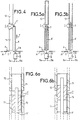
- Figure 4 is a schematic sectional view of an antenna which is distinguished from the antenna according to FIG. 1 only by the module of switching and control device of this module.
- the Figure 4 shows a unipolar antenna with variable geometry with: - the same radiating part 1 made of two conductive sections, aligned 11, 12 separated by an interval with, associated with this interval, a switching module, 2 ', consisting of a two-state relay, open-closed, of the mechanical switch type, - a ground plane M arranged like the one in figure 1 - and a transmission-reception access between the plane and a terminal A located at the bottom of the conductive section 11.
- the control of the mechanical switch 2 ' is provided by an assembly consisting of a plunger core coil, 5, the movable part 51 of which is extended by a rod 6 made of a material insulating, transparent to electromagnetic waves.
- the coil is located under the ground plane M through which the rod 6 passes through a hole Tm.
- the rod is bent at a right angle and comes into contact with the switch blade 2 '.
- FIGS 5a, 5b are schematic sectional views which correspond to an alternative embodiment of the antenna according to the figure 4; in this realization, always with the same type of antenna, the switching of the conductive section 12 is done by a module switching consisting of a conductive sleeve 7 which can slide inside the hollow sections 11 and 12, against the part of these sections located in the vicinity of the interval between them; this sleeve thus plays a role of mechanical relay in two states, open-closed, between the hollow sections 11 and 12.
- a plunger core coil, 5 is used; it is located under the ground plane M, directly above the hole T drilled in the ground plane under the radiating part 1.
- the part mobile 51 of the coil 5 is extended by a rod 6 '.
- This rod is a straight rod which penetrates, at its upper end, into the sleeve 7 in which it is blocked.
- the movable part 51 is in the retracted position or output as shown respectively in Figures 5a and 5b.
- the conductive sleeve 7 does contact with section 11, so that the antenna is designed to operate with only this section as a radiating element.
- the conductive sleeve 7 makes contact with the two sections 11 and 12 and, this time, the antenna is designed to operate with the two sections 11 and 12 as radiant elements.
- FIGS 6a, 6b are schematic sectional views which correspond to an alternative embodiment of the antenna according to the invention.
- a module for 7 'switching is used which, instead of ensuring a connection by conductive element between two radiating sections, ensures connection by capacitive coupling.
- this antenna is not distinguished from the antenna according to FIGS. 5a, 5b only by the switching module 7 '; therefore it was considered preferable, to bring out the difference, to show, in Figures 6a, 6b only the part of the antenna located at neighborhood of the switching module.
- the switching module 7 ' has two sleeves: one inner sleeve 70 an outer sleeve 71.
- the inner sleeve is a conductive sleeve; an insulating rod, 6 ', identical to the rod 6' according to Figures 5a, 5b enters the sleeve 70, at its end upper and is locked inside the sleeve.
- the sleeve outer, thin, is a dielectric sleeve, blocked, with its lower part, inside a hollow, conductive section 11 and, at its upper part, inside a hollow conductive section 12.
- the inner sleeve 70 slides in the outer section 71.
- the rod 6 ' is shown in the lower position, with the sleeve 70 entirely contained in section 11; in this position the module 7 'does not provide an electrical connection between the sections 11 and 12.
- the rod 6 ' is shown in the high position, with the sleeve 70, the lower part of which is contained in the section 11 and the upper part in the section 12.
- the facing portions of the section 11 and of the sleeve 70 on the one hand and of the section 12 and of the sleeve 70 on the other hand respectively constitute the plates of two capacitors.
- the sections 11 and 12 are thus connected by these two capacitors arranged in series.
- the dielectric sleeve 71 greatly reduces wear due to sliding since eliminates the friction metal on metal of the realization according to the figures 5a, 5b.
- the section 12 of FIGS. 6a, 6b has a length greater than that of the section 12 of the antenna according to FIGS. 5a, 5b; this is due to the capacity brought by the switching module, capacity which leads a decrease in the electrical length of the antenna.
- the invention is not not limited to the examples described, this is how it can be applied in the case of more than two aligned radiating sections; insulating rods for controlling switching modules can then be arranged next to each other or made so concentric.
- the conductive sleeves of the modules must be drilled eccentric holes to allow the passage of the insulating rods of order modules placed above them. Plus the stems insulation will be curved so that it can be ordered in translation independently of each other, so as to pass the lower modules by eccentric holes and so as to be centered when they enter their respective modules.
- the stems are concentric they must, at at least all except one, have an off-center part at their end lower, to allow control in translation independently of each other.
- the translational commands of the insulating rods can be performed in various ways and, in particular, manually.
- the conductive sections can be full when the rods insulators are external as in the case of FIG. 4.
- Switch modules can consist of sleeves which, instead of penetrating into the conductive sections, surround these conductive sections; but again the module of switching is arranged at the interval between the two sections it switches and switching is ensured by sliding of the conductive sleeve along the sections.
Landscapes
- Physics & Mathematics (AREA)
- Electromagnetism (AREA)
- Variable-Direction Aerials And Aerial Arrays (AREA)
Description
- la figure 1, une vue schématique d'une antenne selon l'invention,
- la figure 2, une vue plus détaillée d'une partie de l'antenne selon la figure 1,
- les figures 3, 4, 5a, 5b, 6a, 6b d'autres vues schématiques relatives à des antennes selon l'invention.
Claims (5)
- Antenne à géométrie variable comportant au moins un alignement de n tronçons conducteurs (11, 12 ; 11a, 11b, 12a, 12b, 13a, 13b) où n est un entier supérieur à 1, séparés électriquement par n-1 intervalles, n-1 modules de commutation (2) respectivement affectés aux n-1 intervalles avec au moins un des modules qui comporte un relais à deux états (R) commandé par deux dispositifs photovoltaïques (21, 22) et, associés à ce module, des moyens de liaison (F1, F2) du type à fibre optique pour fournir de la lumière aux deux dispositifs photovoltaïques, caractérisée en ce que le relais est un relais électromécanique (R) à deux états stables et en ce que les moyens de liaison comportent deux câbles optiques, avec chacun au moins une fibre optique, pour fournir de la lumière respectivement aux deux dispositifs photovoltaïques et commander ainsi respectivement les deux états stables.
- Antenne à géométrie variable comportant au moins un alignement de n tronçons conducteurs (11, 12) où n est un entier supérieur à 1, séparés électriquement par n-1 intervalles, n-1 modules de commutation commandés respectivement par n-1 moyens de commande et respectivement affectés aux n-1 intervalles, avec au moins un des modules qui comporte un relais mécanique (2' ; 7 ; 7') à deux états et dont les moyens de commande comportent une tige mobile (6 ; 6') en un matériau électriquement isolant et transparent aux ondes électriques dont une première extrémité est reliée au relais mécanique, caractérisée en ce que, les tronçons étant situés au dessus d'un plan de masse (M), la tige (6') a sa seconde extrémité située sous le plan de masse, en ce que le relais comporte une pièce conductrice (7 ; 70) solidaire de la première extrémité de la tige et en ce que, pour permettre un couplage entre les deux tronçons (11, 12) séparés par l'intervalle auquel le module comportant le relais est affecté, la pièce conductrice peut coulisser, sous la commande de la tige, parallèlement à l'alignement.
- Antenne selon la revendication 2, caractérisée en ce que la pièce conductrice (7) coulisse directement sur la partie les deux tronçons située au voisinage de l'intervalle auquel le module comportant ce relais est affecté.
- Antenne selon la revendication 2, caractérisée en ce que le relais comporte une pièce en matériau diélectrique (71), solidaire des deux tronçons (11, 12) situés au niveau de l'intervalle auquel le module comportant ce relais est affecté et en ce que la pièce conductrice (70) coulisse en s'appuyant sur la pièce en matériau diélectrique.
- Antenne selon l'une des revendications 2 à 4, caractérisée en ce que les moyens de commande du module avec relais mécanique comportent une bobine à noyau plongeur (5) avec une partie mobile (51) solidaire de la tige (6 ; 6') du relais mécanique.
Applications Claiming Priority (5)
| Application Number | Priority Date | Filing Date | Title |
|---|---|---|---|
| FR9701428A FR2759497A1 (fr) | 1997-02-07 | 1997-02-07 | Antenne a geometrie variable |
| FR9701428 | 1997-02-07 | ||
| FR9800245 | 1998-01-13 | ||
| FR9800245A FR2759498B1 (fr) | 1997-02-07 | 1998-01-13 | Antenne a geometrie variable |
| PCT/FR1998/000232 WO1998035402A1 (fr) | 1997-02-07 | 1998-02-06 | Antenne a geometrie variable |
Publications (2)
| Publication Number | Publication Date |
|---|---|
| EP0958635A1 EP0958635A1 (fr) | 1999-11-24 |
| EP0958635B1 true EP0958635B1 (fr) | 2002-11-13 |
Family
ID=26233304
Family Applications (1)
| Application Number | Title | Priority Date | Filing Date |
|---|---|---|---|
| EP98910784A Expired - Lifetime EP0958635B1 (fr) | 1997-02-07 | 1998-02-06 | Antenne a geometrie variable |
Country Status (7)
| Country | Link |
|---|---|
| US (1) | US6195065B1 (fr) |
| EP (1) | EP0958635B1 (fr) |
| AU (1) | AU6503898A (fr) |
| CA (1) | CA2279987A1 (fr) |
| DE (1) | DE69809392T2 (fr) |
| FR (1) | FR2759498B1 (fr) |
| WO (1) | WO1998035402A1 (fr) |
Families Citing this family (13)
| Publication number | Priority date | Publication date | Assignee | Title |
|---|---|---|---|---|
| FR2790872B1 (fr) * | 1999-03-12 | 2003-05-30 | Thomson Csf | Antenne demontable, a charge capacitive, de type fouet et procede de fabrication d'un segment rayonnant d'une telle antenne |
| FR2818018B1 (fr) | 2000-12-12 | 2003-02-14 | Thomson Csf | Antenne rayonnante a isolation galvanique |
| FR2829622B1 (fr) * | 2001-09-11 | 2004-04-09 | Thales Sa | Systeme antennaire a rendement elevee et a forte puissance |
| FR2837988B1 (fr) * | 2002-03-26 | 2008-06-20 | Thales Sa | Systeme antennaire bi-bande vhf-uhf |
| US6686892B1 (en) * | 2002-04-26 | 2004-02-03 | Bae Systems-Information And Electronic Systems Integration Inc. | Switchable length whip antenna |
| TWI279030B (en) * | 2004-06-21 | 2007-04-11 | Accton Technology Corp | Antenna and antenna array |
| US7050018B2 (en) * | 2004-09-07 | 2006-05-23 | Machine Applications Corp. | Multi-band antenna system |
| US7420516B2 (en) * | 2005-10-11 | 2008-09-02 | Motorola, Inc. | Antenna assembly and method of operation thereof |
| ITLI20090002A1 (it) * | 2009-03-04 | 2010-09-05 | Renzo Friani | Mini antenna verticale, ricetrasmittente, multibanda, motorizzata. composta da elementi fissi e mobili assemblati in modo tale ottenere rendimenti pari ad antenne molto piu' lunghe. |
| CA2761635C (fr) * | 2010-03-24 | 2012-07-10 | Mina Danesh | Cellule photovoltaique et antenne radiofrequence integrees |
| US10003131B2 (en) | 2013-11-19 | 2018-06-19 | At&T Intellectual Property I, L.P. | System and method of optical antenna tuning |
| US10868358B2 (en) * | 2017-10-19 | 2020-12-15 | Harris Solutions NY, Inc. | Antenna for wearable radio system and associated method of making |
| CN112821047A (zh) * | 2021-01-04 | 2021-05-18 | 中国人民解放军海军工程大学 | 一种短波宽带频率可重构的鞭状天线 |
Family Cites Families (12)
| Publication number | Priority date | Publication date | Assignee | Title |
|---|---|---|---|---|
| DE1049556B (fr) * | ||||
| US3129386A (en) * | 1962-05-21 | 1964-04-14 | Sunair Electronics Inc | Automatic antenna impedance matching and loading unit |
| DE1949556A1 (de) * | 1969-10-01 | 1971-04-15 | Bechtold Wolfgang Dipl Ing | Antenne mit elektromechanischen Abstimmelementen |
| GB2100932B (en) * | 1981-06-18 | 1986-06-11 | Charles Edward Cooper | Antenna. |
| US4751513A (en) * | 1986-05-02 | 1988-06-14 | Rca Corporation | Light controlled antennas |
| US4763126A (en) * | 1986-11-04 | 1988-08-09 | Ira Jawetz | Mooring location system |
| US4924238A (en) * | 1987-02-06 | 1990-05-08 | George Ploussios | Electronically tunable antenna |
| US5093668A (en) * | 1989-06-29 | 1992-03-03 | Ball Corporation | Multiple-beam array antenna |
| NL8902812A (nl) * | 1989-11-14 | 1991-06-03 | Tno | Zelfafstembare hoogfrequente antenne. |
| US5367310A (en) * | 1991-10-11 | 1994-11-22 | Southwest Research Institute | Fiber optic antenna radiation efficiency tuner |
| US5293172A (en) * | 1992-09-28 | 1994-03-08 | The Boeing Company | Reconfiguration of passive elements in an array antenna for controlling antenna performance |
| US5656931A (en) * | 1995-01-20 | 1997-08-12 | Pacific Gas And Electric Company | Fault current sensor device with radio transceiver |
-
1998
- 1998-01-13 FR FR9800245A patent/FR2759498B1/fr not_active Expired - Fee Related
- 1998-02-06 US US09/355,918 patent/US6195065B1/en not_active Expired - Lifetime
- 1998-02-06 WO PCT/FR1998/000232 patent/WO1998035402A1/fr not_active Ceased
- 1998-02-06 EP EP98910784A patent/EP0958635B1/fr not_active Expired - Lifetime
- 1998-02-06 CA CA002279987A patent/CA2279987A1/fr not_active Abandoned
- 1998-02-06 AU AU65038/98A patent/AU6503898A/en not_active Abandoned
- 1998-02-06 DE DE69809392T patent/DE69809392T2/de not_active Expired - Lifetime
Also Published As
| Publication number | Publication date |
|---|---|
| DE69809392D1 (de) | 2002-12-19 |
| FR2759498A1 (fr) | 1998-08-14 |
| CA2279987A1 (fr) | 1998-08-13 |
| WO1998035402A1 (fr) | 1998-08-13 |
| EP0958635A1 (fr) | 1999-11-24 |
| FR2759498B1 (fr) | 1999-08-27 |
| US6195065B1 (en) | 2001-02-27 |
| DE69809392T2 (de) | 2003-08-21 |
| AU6503898A (en) | 1998-08-26 |
Similar Documents
| Publication | Publication Date | Title |
|---|---|---|
| WO1998035402A1 (fr) | Antenne a geometrie variable | |
| WO2008155219A1 (fr) | Antenne volumique omnidirectionnelle | |
| WO1981001486A1 (fr) | Dispositif de balayage electronique dans le plan de polarisation | |
| FR2779022A1 (fr) | Station de base de radiocommunication | |
| EP2656438A1 (fr) | Cellule rayonnante a deux etats de phase pour reseau transmetteur | |
| EP1723693B1 (fr) | Antenne a depointage variable comprenant au moins un element dephaseur | |
| WO2005055365A1 (fr) | Antenne configurable et orientable station de base correspondante | |
| EP0121467A1 (fr) | Microconnecteur à haute densité de contacts | |
| EP2625741A1 (fr) | Antenne de grande dimension à ondes de surface et à large bande | |
| FR2999804A1 (fr) | Dispositif d'interconnexion de cellules photovoltaiques a contacts en face arriere, et module comprenant un tel dispositif | |
| FR2977381A1 (fr) | Dephaseur et repartiteur de puissance | |
| CA2460820C (fr) | Antenne a large bande ou multi-bandes | |
| EP1551078B1 (fr) | Antenne omnidirectionnelle configurable | |
| EP2355636A1 (fr) | Ensemble de connexion d'au moins un équipement électronique dans un aéronef | |
| EP0023873B1 (fr) | Limiteur passif de puissance à semi-conducteurs réalisé sur des lignes à structure plane, et circuit hyperfréquence utilisant un tel limiteur | |
| CA2385787A1 (fr) | Reflecteur hyperfrequence actif a bipolarisation, notamment pour antenne a balayage electronique | |
| EP3334033A1 (fr) | Module photovoltaïque et panneau de modules photovoltaïques interconnectes | |
| EP0595726A1 (fr) | Déphaseur d'ondes électromagnétiques et application à une antenne à balayage électronique | |
| FR2685550A1 (fr) | Element reflecteur d'hyperfrequences. | |
| FR2759497A1 (fr) | Antenne a geometrie variable | |
| EP2887454A1 (fr) | Système d'antennes panneau à impact visuel réduit | |
| FR2812771A1 (fr) | Mecanisme de commutateur a isolation par gaz hybride | |
| EP0286464B1 (fr) | Dispositif hyperfréquence à diodes comportant une ligne triplaque | |
| EP1157444A1 (fr) | Antenne a balayage electronique bi-bande, a reflecteur hyperfrequence actif | |
| FR2664432A1 (fr) | Module hyperfrequence triplaque. |
Legal Events
| Date | Code | Title | Description |
|---|---|---|---|
| PUAI | Public reference made under article 153(3) epc to a published international application that has entered the european phase |
Free format text: ORIGINAL CODE: 0009012 |
|
| 17P | Request for examination filed |
Effective date: 19990818 |
|
| AK | Designated contracting states |
Kind code of ref document: A1 Designated state(s): BE CH DE ES FR GB IT LI NL SE |
|
| RAP1 | Party data changed (applicant data changed or rights of an application transferred) |
Owner name: THALES |
|
| GRAG | Despatch of communication of intention to grant |
Free format text: ORIGINAL CODE: EPIDOS AGRA |
|
| 17Q | First examination report despatched |
Effective date: 20020212 |
|
| GRAG | Despatch of communication of intention to grant |
Free format text: ORIGINAL CODE: EPIDOS AGRA |
|
| GRAH | Despatch of communication of intention to grant a patent |
Free format text: ORIGINAL CODE: EPIDOS IGRA |
|
| GRAH | Despatch of communication of intention to grant a patent |
Free format text: ORIGINAL CODE: EPIDOS IGRA |
|
| GRAA | (expected) grant |
Free format text: ORIGINAL CODE: 0009210 |
|
| AK | Designated contracting states |
Kind code of ref document: B1 Designated state(s): BE CH DE ES FR GB IT LI NL SE |
|
| PG25 | Lapsed in a contracting state [announced via postgrant information from national office to epo] |
Ref country code: NL Free format text: LAPSE BECAUSE OF FAILURE TO SUBMIT A TRANSLATION OF THE DESCRIPTION OR TO PAY THE FEE WITHIN THE PRESCRIBED TIME-LIMIT Effective date: 20021113 Ref country code: IT Free format text: LAPSE BECAUSE OF FAILURE TO SUBMIT A TRANSLATION OF THE DESCRIPTION OR TO PAY THE FEE WITHIN THE PRESCRIBED TIME-LIMIT;WARNING: LAPSES OF ITALIAN PATENTS WITH EFFECTIVE DATE BEFORE 2007 MAY HAVE OCCURRED AT ANY TIME BEFORE 2007. THE CORRECT EFFECTIVE DATE MAY BE DIFFERENT FROM THE ONE RECORDED. Effective date: 20021113 |
|
| REG | Reference to a national code |
Ref country code: GB Ref legal event code: FG4D Free format text: NOT ENGLISH |
|
| REG | Reference to a national code |
Ref country code: CH Ref legal event code: EP |
|
| REF | Corresponds to: |
Ref document number: 69809392 Country of ref document: DE Date of ref document: 20021219 |
|
| PG25 | Lapsed in a contracting state [announced via postgrant information from national office to epo] |
Ref country code: SE Free format text: LAPSE BECAUSE OF FAILURE TO SUBMIT A TRANSLATION OF THE DESCRIPTION OR TO PAY THE FEE WITHIN THE PRESCRIBED TIME-LIMIT Effective date: 20030213 |
|
| PG25 | Lapsed in a contracting state [announced via postgrant information from national office to epo] |
Ref country code: LI Free format text: LAPSE BECAUSE OF NON-PAYMENT OF DUE FEES Effective date: 20030228 Ref country code: CH Free format text: LAPSE BECAUSE OF NON-PAYMENT OF DUE FEES Effective date: 20030228 Ref country code: BE Free format text: LAPSE BECAUSE OF NON-PAYMENT OF DUE FEES Effective date: 20030228 |
|
| NLV1 | Nl: lapsed or annulled due to failure to fulfill the requirements of art. 29p and 29m of the patents act | ||
| GBT | Gb: translation of ep patent filed (gb section 77(6)(a)/1977) |
Effective date: 20030312 |
|
| PG25 | Lapsed in a contracting state [announced via postgrant information from national office to epo] |
Ref country code: ES Free format text: LAPSE BECAUSE OF FAILURE TO SUBMIT A TRANSLATION OF THE DESCRIPTION OR TO PAY THE FEE WITHIN THE PRESCRIBED TIME-LIMIT Effective date: 20030529 |
|
| PLBE | No opposition filed within time limit |
Free format text: ORIGINAL CODE: 0009261 |
|
| STAA | Information on the status of an ep patent application or granted ep patent |
Free format text: STATUS: NO OPPOSITION FILED WITHIN TIME LIMIT |
|
| REG | Reference to a national code |
Ref country code: CH Ref legal event code: PL |
|
| 26N | No opposition filed |
Effective date: 20030814 |
|
| REG | Reference to a national code |
Ref country code: FR Ref legal event code: PLFP Year of fee payment: 19 |
|
| REG | Reference to a national code |
Ref country code: FR Ref legal event code: PLFP Year of fee payment: 20 |
|
| PGFP | Annual fee paid to national office [announced via postgrant information from national office to epo] |
Ref country code: DE Payment date: 20170131 Year of fee payment: 20 Ref country code: FR Payment date: 20170126 Year of fee payment: 20 |
|
| PGFP | Annual fee paid to national office [announced via postgrant information from national office to epo] |
Ref country code: GB Payment date: 20170203 Year of fee payment: 20 |
|
| REG | Reference to a national code |
Ref country code: DE Ref legal event code: R071 Ref document number: 69809392 Country of ref document: DE |
|
| REG | Reference to a national code |
Ref country code: GB Ref legal event code: PE20 Expiry date: 20180205 |
|
| PG25 | Lapsed in a contracting state [announced via postgrant information from national office to epo] |
Ref country code: GB Free format text: LAPSE BECAUSE OF EXPIRATION OF PROTECTION Effective date: 20180205 |