EP0958221B1 - Load roll arrangement - Google Patents
Load roll arrangement Download PDFInfo
- Publication number
- EP0958221B1 EP0958221B1 EP97938875A EP97938875A EP0958221B1 EP 0958221 B1 EP0958221 B1 EP 0958221B1 EP 97938875 A EP97938875 A EP 97938875A EP 97938875 A EP97938875 A EP 97938875A EP 0958221 B1 EP0958221 B1 EP 0958221B1
- Authority
- EP
- European Patent Office
- Prior art keywords
- arrangement
- load
- winding
- support beam
- accordance
- Prior art date
- Legal status (The legal status is an assumption and is not a legal conclusion. Google has not performed a legal analysis and makes no representation as to the accuracy of the status listed.)
- Expired - Lifetime
Links
Images


Classifications
-
- B—PERFORMING OPERATIONS; TRANSPORTING
- B65—CONVEYING; PACKING; STORING; HANDLING THIN OR FILAMENTARY MATERIAL
- B65H—HANDLING THIN OR FILAMENTARY MATERIAL, e.g. SHEETS, WEBS, CABLES
- B65H18/00—Winding webs
- B65H18/08—Web-winding mechanisms
- B65H18/14—Mechanisms in which power is applied to web roll, e.g. to effect continuous advancement of web
- B65H18/20—Mechanisms in which power is applied to web roll, e.g. to effect continuous advancement of web the web roll being supported on two parallel rollers at least one of which is driven
-
- B—PERFORMING OPERATIONS; TRANSPORTING
- B65—CONVEYING; PACKING; STORING; HANDLING THIN OR FILAMENTARY MATERIAL
- B65H—HANDLING THIN OR FILAMENTARY MATERIAL, e.g. SHEETS, WEBS, CABLES
- B65H18/00—Winding webs
- B65H18/08—Web-winding mechanisms
- B65H18/26—Mechanisms for controlling contact pressure on winding-web package, e.g. for regulating the quantity of air between web layers
-
- B—PERFORMING OPERATIONS; TRANSPORTING
- B65—CONVEYING; PACKING; STORING; HANDLING THIN OR FILAMENTARY MATERIAL
- B65H—HANDLING THIN OR FILAMENTARY MATERIAL, e.g. SHEETS, WEBS, CABLES
- B65H2301/00—Handling processes for sheets or webs
- B65H2301/40—Type of handling process
- B65H2301/41—Winding, unwinding
- B65H2301/414—Winding
- B65H2301/4148—Winding slitting
- B65H2301/41486—Winding slitting winding on two or more winding shafts simultaneously
- B65H2301/414866—Winding slitting winding on two or more winding shafts simultaneously on bed rollers
-
- B—PERFORMING OPERATIONS; TRANSPORTING
- B65—CONVEYING; PACKING; STORING; HANDLING THIN OR FILAMENTARY MATERIAL
- B65H—HANDLING THIN OR FILAMENTARY MATERIAL, e.g. SHEETS, WEBS, CABLES
- B65H2404/00—Parts for transporting or guiding the handled material
- B65H2404/40—Shafts, cylinders, drums, spindles
- B65H2404/43—Rider roll construction
Definitions
- the invention pertains to a load roll arrangement of the type corresponding to the preamble of Claim 1.
- winding cores or the wound roll are pressed down into the winding bed by means of an arrangement of load rolls in order to ensure, particularly during the initial phase, a good engagement of the wound rolls that are forming and in the later phase, a perfect formation of the wound rolls.
- the load roll arrangement consists of many individual rolls successiveively arranged in transverse direction with respect to the web, which rolls are pivotably mounted on arms and rest on top of the wound rolls independently of each other. In this way, a uniform resting on all wound rolls or a deliberately uneven resting can be achieved.
- the arms of the load rolls are arranged at a support beam, provided centrally above the support drums, which can be raised and lowered vertically and which, in the initial phase, is lowered closely above the support drums and rises with an increasing wound roll diameter.
- winding cores of a set were customary to have the same diameter. Lately, however, it is required that within a winding core set, winding cores of varying diameters may also be used.
- the conventional load roll arrangements have indeed a certain adaptability and, by means of an appropriate swiveling motion of the support arms, are able to handle differences in height, i.e., differences of up to 35 mm in diameter of the winding cores placed in the winding bed.
- the adjustment arrangement in accordance with Claim 2 may comprise individual adjustment units that engage the respective mounting arrangement.
- the mounting arrangement is a structural unit that comprises, respectively, a carrier for the support arms that can be swiveled up and down, the support arms themselves and the force member that, while the support arms are swiveled, press the respective load roll onto the wound roll.
- the simplest approach is displacement of the mounting arrangement with respect to the support beam on a slide guide.
- the advance of the connecting rod, in accordance with Claim 7, may take place by means of a control element present in each adjustment unit which, according to Claim 8, is in the form of a cam plate.
- a structurally simple solution for driving these cam plates is the common adjustment shaft on which all cam plates are rotatably mounted and which via drag levers are engaged selectively by the cam plate or not, depending on whether the latch connecting both is engaged or not.
- the adjustment shaft does not rotate continuously but merely covers a pivot angle range of, for example 270°, wherein the one critical angle causes the connecting rod to be lifted and a height adjustment of the load roll which, for example, corresponds to the greatest existing winding core diameter and the other limit is laid out correspondingly for the smallest winding core diameter.
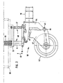
- the roll cutting machine serves for separating an incoming paper web 30, having the width of the paper machine, into individual narrower webs 34, and by means of the roll cutting device, having a pair of circular cutters 31, 32 and represented overall by 33, wherein the individual narrower webs, separated as a result of the longitudinal cuts, continue to pass directly adjacent to one another through the roll cutting machine 100, over and around the left of the two parallel extending support drums 35, 36, having the same diameter and arranged at the same height, onto the wound rolls W, which are forming directly side by side but separately on the two support drums 35, 36 that extend across the width of the original paper web 30.
- the wound rolls W are wound to diameters on the order of 1.5 m on so-called winding cores in the form of strong cardboard tubes with outer diameters of approximately 100 to 200 mm.
- the winding cores are placed, in a manner yet to be explained by means of Figures 3 and 4, into the winding bed 37, either manually or with an appropriate device, are joined with the beginnings of the web, for example, by gluing, and are then made to rotate by means of the drive of the support drums 35, 36, on which they are supported.
- a multipart load roll 40 arranged symmetrically above the support drums 35, 36 and parallel to the support drums 35, 36 which can be lifted and lowered in accordance with the winding operation in progress, in the direction of the arrow and with respect to a horizontal support beam 60 extending diagonally across the web width.
- each individual load roller 42 independently of the other load rollers, can be swiveled up or down on bearing cheeks 41, arranged on both sides about a horizontal swivel axis 43 located outside the periphery of the load roller 42.
- the stub axle 45 with the swivel axis 43 is arranged at a carrier 44, which extends upwardly from the swivel axis 43 and carries at a distance, above the swivel axis 43, a horizontally effective force member 46, for example, a fluid cylinder, which acts against the end 41' of the bearing cheeks 41, located above the swivel axis 43, and by means of which the bearing cheeks 41 can be swiveled about a limited angle that approximately corresponds to a vertical lift of the load rollers 42 by up to 35 mm.
- the load force of the load rollers 42 on the wound rolls W is determined by the force of the force member 46 and can be controlled in this manner.
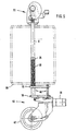
- the carrier 44 is attached to a horizontal mounting plate 16 that can be raised and lowered in the direction of the arrow 47 with respect to the support beam 60.
- the entire structural unit consisting of bearing cheeks 41, carrier 44 and mounting plate 16 can be described as a mounting arrangement 50 that can be raised and lowered in the direction of the arrow 47.
- the mounting arrangement 50 is guided on a slide guide 48, which comprises a vertical connecting rod 6 that with its lower end grips into a bore hole of the mounting plate 16 to which it is clamped.
- pilots 17 are attached which support the guide.
- a guide plate 15 is rigidly arranged through which the connecting rod 6 and the guide pilot 17 grip and which affects their slide guide.
- the mounting arrangement 50 with the load rollers 42 may be raised in the direction of the arrow 47 with respect to the lowest position shown in Figure 2 until the mounting plate 16 rests against the guide plate 15.
- each individual load roller 42 can also be adjusted individually, i.e., from the lowest position, shown in Figure 3, to an upper position shown in Figure 4.
- the lift between the two positions is approximately 90 mm, to which the small lift of the load rollers 42, due to swiveling of the bearing cheeks 41, may be added.
- the respective connecting rod 6, serving for the purpose of guiding and lifting the mounting arrangement 50 vertically grips through the support beam 60, which is in the form of a box support.
- the connecting rod 6 is surrounded by a helical spring 18 that, with its lower end, supports itself on the upper surface of the guide plate 15 and with its upper end supports itself against a support 20 at the connecting rod 6.
- the helical spring 18 assures that the mounting arrangement 50 is normally located in the lifted position shown in Figure 6.
- the adjustment unit 70 While the mounting arrangement 50 with its slide guide 48 is arranged at the underside of the support beam 60, the adjustment unit 70, assigned to each mounting arrangement 50, is located on the upper surface of the support beam 60. The adjustment unit 70 transfers its lift via the connecting rod 6 to the mounting arrangement 50.
- Each adjustment unit comprises a cam plate 1 with a latch 3, rotatably mounted on it.
- a cam plate 1 is assigned to each load roller 42.
- All cam plates 1 are rotatably mounted on an adjustment shaft 10 that extends along the support beam 60 and is arranged above the upper end of the connecting rods 6.
- the upper end of the connecting rods 6 carries a roll 23, which is intended to engage with the periphery of the cam plate 1.
- the mounting of the latch 3 on the bearing pin 24 is in the area of the greatest radial distance of the cam plate 1.
- the latch 3 is in the form of a two-armed lever, whose extension 25, located at the end of the upper lever in Figure 7, points in the radially inward direction with respect to the adjustment shaft 10.
- a drag lever 2 is connected without rotational play ( Figure 9) which is located in the same plane, perpendicular to the axis A of the adjustment shaft 10 as the latch 3 and has a recess 26 on its outer boundary surface into which the extension 25 of the latch 3 grips.
- a leg spring 4 is arranged which normally presses the latch 3 with its extension 25 into the recess 26 of the drag lever 2.
- the cam plates 1 are fixed in the axial direction of the adjustment shaft 10 by means of spacer sleeves 14, which rest laterally against the drag levers 2.
- a control element in the form of a short-stroke cylinder 5 is fixed, i.e., connected to the support beam 60, that, during operation in the manner visible in Figure 8, moves the latch 3 in such a way that its extension 25 no longer engages the recess 26 of the drag lever 2.
- the adjustment shaft 10 is supported several times in bearing blocks 9 on the upper surface of the support beam 60 and is rotatably mounted via friction bearings.
- the adjustment shaft 10 is turned back in the counterclockwise direction by means of a rotary drive unit, (not shown) located at its free end, by a maximum of 270° in accordance with the Figures 7 and 8.
- one portion of the short-stroke cylinders 5 is controlled and another portion is not, depending on whether the respective cam plate 1 is located above a winding core 21 with a small diameter or a winding core 22 with a larger diameter.
- the nonactivated cam plates 1 are not turned but are at a standstill, so that also the assigned connecting rods 6 remain in their upper position that, according to Figure 4, is adapted to the winding cores 22 with the greater diameter.
- cam plates 1 which of the cam plates 1 are “activated” in the individual case depends on the actual set of winding cores, i.e., on the order of the winding cores 21, 22, with the smaller or greater diameter and its length.
- the appropriate data reach the control that "activates” the accompanying cam plate 1 for all load rollers 42 that are located within the longitudinal extension of a winding core 21 with a smaller winding diameter, in order to move the appropriate mounting arrangement from the position according to Figure 4 into that according to Figure 3.
- the adjustment of the mounting arrangements 50 need not necessarily correspond to the outermost angle positions of the cam plate 1, which are assigned to the maximally smallest or greatest occurring winding core diameters. Perhaps, in addition to the initial position shown in the Figures 7 and 8, which corresponds to the greatest winding core diameter, it would be possible to use an intermediate position of the angle of rotation of the adjustment shaft 10, in which the engaged cam plates 1 are held. This intermediate position then corresponds to a central diameter of a winding core.
- each adjustment unit 70 has positioned the accompanying load roller in accordance with the actual winding core set, all controlled short-stroke cylinders 5 (above the large winding cores 22) are switched without power.
- the respective latch 3 remains pressed via the leg spring 4 against the retracted ram of the short-stroke cylinder 5 and, at that point, extends with its lower end across a rail 12 on which it supports itself and thereby fixes the accompanying cam plate 1 in its position.
- the remaining differences between the smaller or larger winding cores 21, 22 are so small that the adjustment units 70, starting with this area, can again assume their zero-degree position and all of the mounting arrangements 50 rest again against the respective guide plate 15 at the underside of the support beam 60.
- the load roll 40 or the support beam 60 with all attaching parts receives its reference position from the wound rolls W with large winding cores 22, on which it rests in a power-controlled or power-regulated manner. This position is determined by means of a position measurement. Since the increase in area in the above-mentioned manner is known and thus also the respective difference in diameter, it is possible to turn the adjustment shaft 10, via a control program in appropriate timed angle steps, back to the initial zero position.
- the adjustment device comprising the adjustment units 70, is an additional arrangement that can be integrated in existing load arrangements with individual load rollers, which are arranged closely side by side, without the need to alter the load rollers with their suspensions or the accompanying control of the support beam.
Landscapes
- Winding Of Webs (AREA)
- Replacement Of Web Rolls (AREA)
- Spinning Or Twisting Of Yarns (AREA)
- Crushing And Grinding (AREA)
- Rolls And Other Rotary Bodies (AREA)
- Winding, Rewinding, Material Storage Devices (AREA)
Description
- 1
- Cam plate
- 2,2'
- Drag lever
- 3
- Latch
- 4
- Leg spring
- 5
- Short-stroke cylinder
- 6
- Connecting rod
- 9
- Bearing blocks
- 10
- Adjustment shaft
- 12
- Rail
- 14
- Spacer sleeves
- 15
- Guide plate
- 16
- Mounting plate
- 17
- Guide pilot
- 18
- Helical spring
- 20
- Support
- 21,21'
- Small winding core
- 22,22'
- Large winding core
- 23
- Roll
- 24
- Bearing pin
- 25
- Extension of latch
- 26
- Recess of drag lever
- 30
- Paper web
- 31
- Circular cutter
- 32
- Circular cutter
- 33
- Roll cutting device
- 34
- Narrower web
- 35
- Support drum
- 36
- Support drum
- 37
- Winding bed
- 40
- Multipart load roll
- 41
- Bearing cheeks
- 41'
- End of bearing cheek
- 42
- Load rollers
- 42'
- Normal Position
- 43
- Swivel axis
- 44
- Carrier
- 45
- Stub axle
- 46
- Force members
- 47
- Arrow
- 48
- Slide guide
- 50
- Mounting arrangement
- 60
- Support beam
- 70
- Adjustment unit
- 100
- Rolling cutting machine
- A
- Axis
- w
- Wound rolls
- N
- Nip
Claims (12)
- Load roll arrangement for loading a winding arrangement with one wound roll or several wound rolls (W) on the same axis, during the winding of a web-like material, particularly paper, onto winding cores in a multiple-drum winder that comprises support drums (35, 36), rotating about horizontal axes, which are parallel to each other and closely arranged side by side, wherein the support drums (35, 36) form a winding bed (37), in which the winding arrangement, rotating about its axis, is supported,characterized by an additional adjustment device, by means of which the mounting arrangements (50) of the individual load rollers (42) can be moved to different heights, independently of each other with respect to the support beam (60) according to the specifications of the resulting differences in diameter of the winding cores (21, 22).with a support beam (60), vertically movable dependent upon the wound roll diameter,with drive means for moving the support beam (60),with a multipart load roll (40), essentially parallel to the axes of the support drums (35, 36), consisting of a number of load rollers (42), which, individually with respect to the support beam (60), are vertically movable on a mounting arrangement and can be maintained in contact with the wound roll (W) along a nip (N)and with means for the fluid-like, particularly hydraulic, pressing of the load rollers (42) against the winding arrangement,
- Load roll arrangement, in accordance with Claim 1, characterized in that the adjustment arrangement for each individual load roller (42) comprises its own adjustment unit (70), engaging the respective mounting arrangement (50), and in that the individual adjustment units (70) are operated independently of each other.
- Load roll arrangement, in accordance with Claim 1 or 2, characterized in that the respective mounting arrangement (50) can be moved vertically with respect to the support beam (60) along a slide guide (48) by means of the adjustment unit (70).
- Load roll arrangement, in accordance with Claim 3, characterized in that the mounting arrangement (50) is arranged under the support beam (60) and the respectively assigned adjustment unit (70) is arranged on top of the support beam (60) and the vertical displacement of the mounting arrangement (50) respectively takes place by means of one connecting rod (6), vertically gripping through the support beam (60), displaced by the adjustment unit (70), and engaging the mounting arrangement (50).
- Load roll arrangement, in accordance with one of the Claims 1 to 4, characterized in that the mounting arrangement (50) is pressed in a resilient manner into the upper position that is adjacent to the support beam (60).
- Load roll arrangement, in accordance with Claim 5, characterized in that the connecting rod (6) is surrounded in the interior of the support beam (60) by a helical spring (18) that, at the lower end supports itself at the support beam (60) and at the upper end at an abutment (20) on the connecting rod (6).
- Load roll arrangement, in accordance with one of the Claims 4 to 6, characterized in that each adjustment unit (70) comprises an control element effecting a controllable advance of the connecting rod (6).
- Load roll arrangement, in accordance with Claim 7, characterized in that the control element comprises a cam plate (1), rotatable about an axis (A) that is parallel to the axes of the support drums (35, 36) and has an effect on the upper end of the connecting rod (6).
- Load roll arrangement, in accordance with Claim 8, characterized in that for all cam plates (1), a common adjustment shaft (10) is provided which simultaneously serves as a pivot bearing of the cam plates (1) and which selectively can be rotatably connected to the individual cam plates (1).
- Load roll arrangement, in accordance with Claim 9, characterized in that at the adjustment shaft (10), for each cam plate (1), respectively, one drag lever (2) is mounted without rotational play, which can be coupled to the cam plate (1) by means of a latch (3) which by means of a control (5) can be prevented from being engaged.
- Load roll arrangement, in accordance with Claim 9 or 10, characterized in that the adjustment shaft (10) can be driven via a pivot angle range, whose limit angles correspond to the winding cores (21, 22) with the smallest or greatest diameters.
- Load roll arrangement, in accordance with Claim 11, characterized in that by means of starting in intermediate positions of the pivot angle range of the cam plates (1), an adaptation to intermediate sizes of the winding cores takes place.
Applications Claiming Priority (3)
| Application Number | Priority Date | Filing Date | Title |
|---|---|---|---|
| DE29613350U | 1996-08-05 | ||
| DE29613350U DE29613350U1 (en) | 1996-08-05 | 1996-08-05 | Load roller assembly |
| PCT/EP1997/004251 WO1998005578A1 (en) | 1996-08-05 | 1997-08-05 | Load roll arrangement |
Publications (2)
| Publication Number | Publication Date |
|---|---|
| EP0958221A1 EP0958221A1 (en) | 1999-11-24 |
| EP0958221B1 true EP0958221B1 (en) | 2001-12-12 |
Family
ID=8027300
Family Applications (1)
| Application Number | Title | Priority Date | Filing Date |
|---|---|---|---|
| EP97938875A Expired - Lifetime EP0958221B1 (en) | 1996-08-05 | 1997-08-05 | Load roll arrangement |
Country Status (8)
| Country | Link |
|---|---|
| US (1) | US6170777B1 (en) |
| EP (1) | EP0958221B1 (en) |
| JP (1) | JP2000515472A (en) |
| AU (1) | AU4117097A (en) |
| CA (1) | CA2262548C (en) |
| DE (2) | DE29613350U1 (en) |
| ES (1) | ES2170411T3 (en) |
| WO (1) | WO1998005578A1 (en) |
Families Citing this family (7)
| Publication number | Priority date | Publication date | Assignee | Title |
|---|---|---|---|---|
| US20020017122A1 (en) * | 2000-04-01 | 2002-02-14 | Mccabe Troy A. | Wire containment apparatus for wire drawing machines |
| DE10348707A1 (en) * | 2003-10-16 | 2005-05-12 | Saurer Gmbh & Co Kg | Device for the control of the contact pressure of a textile bobbin on a support or drive roller |
| DE102008018890A1 (en) * | 2008-04-14 | 2009-10-29 | Ancient Energy Gmbh & Co. Kg | Apparatus and method for winding web-shaped materials |
| DE102009027141A1 (en) * | 2009-06-24 | 2010-12-30 | Voith Patent Gmbh | Winding method and roll winder |
| EP2653422B1 (en) * | 2012-04-20 | 2015-06-03 | Valmet Technologies, Inc. | Method and device for winding of fiber webs, especially of partial paper and board webs |
| CN104227903B (en) * | 2014-10-08 | 2016-06-08 | 无锡双象橡塑机械有限公司 | Rubber weighs devices for taking-up |
| FI127840B (en) * | 2017-03-23 | 2019-03-29 | Valmet Technologies Oy | A method of controlling operation of a winder for a fiber web |
Family Cites Families (11)
| Publication number | Priority date | Publication date | Assignee | Title |
|---|---|---|---|---|
| FR2049494A5 (en) * | 1969-06-11 | 1971-03-26 | Ruby Ets | |
| DE6944109U (en) * | 1969-11-13 | 1970-05-27 | Ahlstroem Oy | DEVICE FOR WINDING UP A RUNNING TAPE. |
| US3602448A (en) * | 1970-02-03 | 1971-08-31 | Alcan Res & Dev | Web-winding apparatus |
| GB1291310A (en) * | 1970-09-22 | 1972-10-04 | Baker Perkins Ltd | Lidding apparatus |
| DE2342515C2 (en) * | 1973-08-23 | 1975-10-02 | Erwin Kampf Maschinenfabrik, 5276 Wiehl | Roll winding machine |
| FI53561C (en) * | 1976-03-12 | 1978-06-12 | Ahlstroem Oy | BELASTNINGSVALS I RULLMASKIN |
| DE2633408C2 (en) * | 1976-07-24 | 1978-06-15 | Jagenberg-Werke Ag, 4000 Duesseldorf | Pressure roller arrangement in a winding machine for webs of material to be wound |
| DE3832601C1 (en) * | 1988-09-26 | 1989-12-07 | J.M. Voith Gmbh, 7920 Heidenheim, De | Winding machine for web-like material, especially paper |
| DE9201791U1 (en) * | 1991-12-13 | 1992-04-09 | J.M. Voith Gmbh, 7920 Heidenheim | Winding machine for winding a web, in particular a paper web |
| US5320299A (en) | 1992-01-27 | 1994-06-14 | Beloit Technologies, Inc. | Articulated rider roll system and method |
| DE29507313U1 (en) | 1995-05-06 | 1996-09-05 | Beloit Technologies, Inc., Wilmington, Del. | Load roller assembly |
-
1996
- 1996-08-05 DE DE29613350U patent/DE29613350U1/en not_active Expired - Lifetime
-
1997
- 1997-08-05 WO PCT/EP1997/004251 patent/WO1998005578A1/en active Search and Examination
- 1997-08-05 ES ES97938875T patent/ES2170411T3/en not_active Expired - Lifetime
- 1997-08-05 AU AU41170/97A patent/AU4117097A/en not_active Abandoned
- 1997-08-05 CA CA002262548A patent/CA2262548C/en not_active Expired - Fee Related
- 1997-08-05 EP EP97938875A patent/EP0958221B1/en not_active Expired - Lifetime
- 1997-08-05 DE DE69709173T patent/DE69709173T2/en not_active Expired - Fee Related
- 1997-08-05 US US09/230,700 patent/US6170777B1/en not_active Expired - Fee Related
- 1997-08-05 JP JP10507617A patent/JP2000515472A/en active Pending
Also Published As
| Publication number | Publication date |
|---|---|
| CA2262548A1 (en) | 1998-02-12 |
| WO1998005578A1 (en) | 1998-02-12 |
| US6170777B1 (en) | 2001-01-09 |
| AU4117097A (en) | 1998-02-25 |
| DE69709173D1 (en) | 2002-01-24 |
| ES2170411T3 (en) | 2002-08-01 |
| DE29613350U1 (en) | 1997-12-04 |
| EP0958221A1 (en) | 1999-11-24 |
| CA2262548C (en) | 2004-07-20 |
| JP2000515472A (en) | 2000-11-21 |
| DE69709173T2 (en) | 2002-07-25 |
Similar Documents
| Publication | Publication Date | Title |
|---|---|---|
| US5673870A (en) | Method and apparatus for reeling a traveling paper web | |
| EP0776313B1 (en) | Improved method and apparatus for reeling a traveling web into a wound web roll | |
| KR100202227B1 (en) | Rewinder for producing log of web material, selectively with or without a winding core | |
| US5816528A (en) | Reel-up with double secondary units for reeling a running web in a paper machine | |
| DE3539980C2 (en) | Method and device for controlling a paper web rewinder | |
| DE69508422T2 (en) | WINDING MACHINE WITH LIFTED WINDING RAIL | |
| US5967449A (en) | Winder and method for the continuous winding of a material web | |
| CA1318900C (en) | Apparatus for winding webs of material | |
| CA2304623A1 (en) | Continuous winder | |
| US4979689A (en) | Method and apparatus for winding a web | |
| ITFI980131A1 (en) | WINDING OR REWINDING MACHINE FOR THE FORMATION OF ROLLS OF BIG DIAMETER TAPE MATERIAL | |
| US5273222A (en) | Multiple-station winding machine for the winding of webs of foil or the like | |
| US4988051A (en) | Method of winding continuously supplied material on several cores and double backing-roller winder | |
| EP0912433B1 (en) | Rider roll unit for winding machines | |
| CA2115655C (en) | Support-roller-type winding machine | |
| EP0958221B1 (en) | Load roll arrangement | |
| US3162393A (en) | Tucking means for a web-winding machine | |
| US4789109A (en) | Web winding method and winder | |
| EP1135316B1 (en) | Reel-up and method for reeling of a web | |
| US6149098A (en) | Process to spool a longitudinally cut material sheet and a device to execute the process | |
| CA2039876A1 (en) | Winder for winding a running web | |
| CA2080625C (en) | Cutting device for a winding machine for winding a web of material, particularly a paper web | |
| EP1075444B1 (en) | Device and method for applying a load to a reel in a reel-up of a paper web | |
| JP2623173B2 (en) | Automatic winding method and device | |
| US6164586A (en) | Support drum assembly with cross-shaft linkage for variable backlash control |
Legal Events
| Date | Code | Title | Description |
|---|---|---|---|
| PUAI | Public reference made under article 153(3) epc to a published international application that has entered the european phase |
Free format text: ORIGINAL CODE: 0009012 |
|
| 17P | Request for examination filed |
Effective date: 19990528 |
|
| AK | Designated contracting states |
Kind code of ref document: A1 Designated state(s): DE ES |
|
| GRAG | Despatch of communication of intention to grant |
Free format text: ORIGINAL CODE: EPIDOS AGRA |
|
| 17Q | First examination report despatched |
Effective date: 20010403 |
|
| RBV | Designated contracting states (corrected) |
Designated state(s): DE ES |
|
| GRAG | Despatch of communication of intention to grant |
Free format text: ORIGINAL CODE: EPIDOS AGRA |
|
| GRAH | Despatch of communication of intention to grant a patent |
Free format text: ORIGINAL CODE: EPIDOS IGRA |
|
| GRAH | Despatch of communication of intention to grant a patent |
Free format text: ORIGINAL CODE: EPIDOS IGRA |
|
| GRAA | (expected) grant |
Free format text: ORIGINAL CODE: 0009210 |
|
| AK | Designated contracting states |
Kind code of ref document: B1 Designated state(s): DE ES |
|
| REF | Corresponds to: |
Ref document number: 69709173 Country of ref document: DE Date of ref document: 20020124 |
|
| REG | Reference to a national code |
Ref country code: ES Ref legal event code: FG2A Ref document number: 2170411 Country of ref document: ES Kind code of ref document: T3 |
|
| PLBE | No opposition filed within time limit |
Free format text: ORIGINAL CODE: 0009261 |
|
| STAA | Information on the status of an ep patent application or granted ep patent |
Free format text: STATUS: NO OPPOSITION FILED WITHIN TIME LIMIT |
|
| 26N | No opposition filed | ||
| PGFP | Annual fee paid to national office [announced via postgrant information from national office to epo] |
Ref country code: ES Payment date: 20050826 Year of fee payment: 9 |
|
| PGFP | Annual fee paid to national office [announced via postgrant information from national office to epo] |
Ref country code: DE Payment date: 20050930 Year of fee payment: 9 |
|
| PG25 | Lapsed in a contracting state [announced via postgrant information from national office to epo] |
Ref country code: DE Free format text: LAPSE BECAUSE OF NON-PAYMENT OF DUE FEES Effective date: 20070301 |
|
| REG | Reference to a national code |
Ref country code: ES Ref legal event code: FD2A Effective date: 20060807 |
|
| PG25 | Lapsed in a contracting state [announced via postgrant information from national office to epo] |
Ref country code: ES Free format text: LAPSE BECAUSE OF NON-PAYMENT OF DUE FEES Effective date: 20060807 |